1
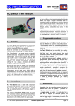
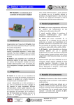
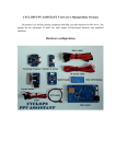
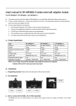
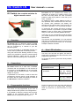
RC Switch I.R.
User manual V. 2.0 05/2005
RC Switch: the complete solution for
digital camera control
RC Switch can be controlled by a switch, by a
pushbutton, by a stick or by a slide on the Tx, and
the user can easily select the most convenient
position to take photo (switch or stick full up, full
down, centered,…).
An additional feature called auto-on function is
also provided; some cameras have an auto shutoff function that preserves the battery life
switching off the camera after a time (from 30” to
90”) with no operation, i.e. if no pictures are taken.
To avoid that the camera will switch off during
remote operation it is possible to program the RC
Switch to take a picture after a programmable
delay from the last command (auto-on function).
In this way you can concentrate yourself in piloting
your model, without the risk of having the camera
switched off.
1.
Overview
RC Switch I.R. is an electronic switch for digital
camera equipped with a I.R. remote control that
can be controlled by a channel of your RC
Receiver system.
This function can be disabled if it is not required
and when it is enabled the time-out interval can be
programmed from few seconds up to 10 minutes
to adapt to different cameras.
It can be connected on a dedicated channel or it
can be used in parallel with an existing function.
4.
Using the infra-red link already present on many
camera it is possible to control the camera without
external interfaces, cables and wit no need to
open the camera and doing some modifications.
Two leds, one red and one green, are used to
signal some conditions and to drive the user in the
programming procedure.
2.
State LED indication
At the start-up (power on) there are three possible
conditions:
Connections
RC Switch board has a cable with a standard
connector that can be fitted in a free channel of
the receiver; if the RC Switch is to be connected
in parallel with an existing function, a Y harness
adaptor is required.
A pushbutton on the switch is used to enter the
programming function and for local activation of
the switch and two state leds display the state of
the RC Switch in different conditions.
Condition
LED indication
1. Memory error or invalid
parameter stored.
Red led flashing at
high rate
2. Start of programming
procedure
Six red blinks
3. Normal function
2 sec. solid green
and then flashing
green every 2 sec.
(see the detailed
description of the
program sequence)
Mode set-up table
3.
Programmable functions
The switch can be programmed by the user to
adapt to different RC systems and configurations.
During the normal function the green led blinks at
every 2” and turns on during output activation
either by command, by internal timeout or local
switch.
It is possible to define the neutral and the active
position of RC command directly on the RC
Switch without modify the setup of your Tx.
RC Switch I.R. instruction manual
www.rc-flysoft.com
Page 1/3
RC Switch I.R.
5.
User manual V. 2.0 05/2005
Power On mode / programming
If the system is powered on normally and the
memory contains valid data, the system starts in
normal function mode, as described in the Mode
set-up table.
At the first activation or if the memory is blank or if
data are not valid, the system starts in error state:
the red led is flashing at high rate and the only
way to restore the normal condition is to restart
the system in programming mode.
Each time the system is powered with the
pushbutton pressed, the programming procedure
starts.
Note the program procedure will not start
automatically when an error is detected in
the data memory: the user must power on
the system with the pushbutton pressed.
If the red led is blinking at high speed the
programming sequence has been aborted for an
error: please verify that the off and the on
commands are not stored at the same value, or at
two values very close and repeat the sequence by
disconnecting and applying power again.
It is recommended to use at least half (50%) of
the command travel (i.e. 0% to 50% or 50% to
100%) and to not modify trim set-up on the
selected channel after system programming.
Auto on function programming: function
enable/disable and timeout interval set-up.
This sequence starts immediately after the end of
the previous one, with the red led switched on for
5 seconds.
1 Sec.
6.
To start the programming sequence, power on the
system with the pushbutton pressed.
1
1
It is now possible to program the command
position and the auto-on function.
Command position set-up:
move to
OFF value
1
1
2
3
4
2 Sec.
…n
Programming procedure
Store OFF
value
move to
ON value
2
3
Store ON
value
4
At power on in program mode you have six
blinks of the red led to set the command in
the neutral position [the position in which
the switch is not active].
2
2
Pressing the pushbutton while the red led is
on disables the auto-on function and
terminates the program sequence.
Otherwise, the auto-on function is enabled,
the time count starts, the green led blinks
at each 0,5” and ends when the pushbutton
is pressed.
In both cases at the end the green led turns on for
2” to indicate that data are saved in memory and
then switches off.
The programming procedure is terminated and the
RC Switch must be powered off and on again for
the new set-up to take effect.
When the led stops blinking the current
position is stored in microcontroller memory
and the red led stays on for 2 seconds;
when the green led starts flashing it is
possible to release the command.
During the four green blinks set the
command in the active position [the position
you prefer to take a picture]…
…and wait for the green led on at the end of
the data store; when the red led turns on it
is possible to release the command.
RC Switch I.R. instruction manual
www.rc-flysoft.com
Page 2/3
RC Switch I.R.
7.
User manual V. 2.0 05/2005
Programming examples
Case 1: you want to program the camera switch
on the aileron channel, taking picture when you
move the stick from the central position to full
right; your camera will switch off after a 30” time
interval with no operation and you decide to
program the auto-on function to take a picture
every 28” in automatic mode to keep camera on.
Case 2: you want to program the camera switch
connected on a Tx switch (two position) operating
on ch. 5, taking picture when you move the switch
up; your camera will not automatically switch off
and you don’t need the auto-on function.
2
You
Operation
RC-Switch
Display
Connect the switch
on the aileron slot
of the receiver,
press the pushbutton and switch
on the system (first
Tx and then Rx).
Move the stick in
neutral position
Effect
Operation
Programming
procedure starts
Connect the switch
on ch 5 on the
receiver, press the
push-button and
switch on the
system (first Tx
and then Rx).
Six red
blinks
Red Led
on
Move the aileron
stick full right and
hold
You
Move the TX
switch to down
(neutral) position
Move the switch to
up position
Green
Led On
Position stored
(active)
Release stick
Red Led
on
Waiting for
time-out enable.
Start counting 28
sec. with a clock or
by counting the led
flashes (one every
0.5 seconds)
Green
Led
flashing
at 0.5”
Counting the
time
Display
Press the pushbutton while led is
on red
Effect
Programming
procedure starts
Six red
blinks
Red Led
on
The current
stick position is
stored (neutral)
Four
green
blinks
RC-Switch
The switch
position is
stored (neutral).
Four
green
blinks
Green
Led on
Position stored
(active)
Red Led
on
time-out
disable.
Green
Led on
Data saved in
memory
Led off
Procedure end
Disconnect power
press the pushbutton after 28”
Green
Led on
Led off
Data saved in
memory
Procedure end
Disconnect power
RC Switch I.R. instruction manual
www.rc-flysoft.com
Page 3/3