1
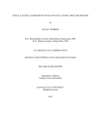
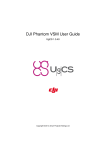
MITOS P-PUMP FLOW CONTROL USER INSTRUCTIONS The Dolomite Centre Ltd. Contents 1. Introduction 3 2. Fluidic Connections 4 3. Electrical Connections 5 4. Manual User Control 7 5. PC Software User Control 11 6. General Notes on Use 12 Appendix A. Updating the Software 13 MAR-000051 v1.3 Page 2 of 14 The Dolomite Centre Ltd. 1. Introduction These user instructions describe how to use the Mitos P-Pump (with flow sensor connected in-line) in flow control mode. Flow control mode allows a flow rate to be selected instead of a pressure and the P-Pump pressure is automatically adjusted to achieve the target flow rate. The benefit of flow control mode is that it accounts for changes in the flow resistance of the system to maintain constant flow rate. To operate in flow control mode, the Mitos Flow Rate Sensor (Part No. 3200096 – 3200100) must be connected to the Mitos P-Pump using either the Mitos Sensor Display (Part No. 3200095) or Mitos Sensor Interface (Part No. 3200200). The table below shows the compatible configurations for newly purchased hardware. Sensor Interface Type Mitos P-Pump Mitos P-Pump Basic Mitos P-Pump Remote Mitos P-Pump Remote Basic (3200016) (3200175) (3200176) (3200177) Mitos Sensor Display (Part No. 3200095) Mitos Sensor Interface (Part No. 3200200) Notes: For users who already own Dolomite products, the following hardware compatibility applies: P-Pumps with serial numbers lower than 160290 are not compatible with any flow sensor interface P-Pumps with serial numbers greater than 160290 but lower than 160444 are only compatible with Mitos Sensor display P-Pumps with serial numbers greater than 160444 are compatible with any flow sensor interface MAR-000051 v1.3 Page 3 of 14 The Dolomite Centre Ltd. 2. Fluidic Connections The flow rate sensor should be connected between the Mitos P-Pump and the microfluidic system as shown below. Connect flow sensor to system Connect P-Pump to flow sensor Mitos Flow Rate Sensor connected to a Mitos P-Pump When using the Mitos P-Pump in flow control mode, flow resistors will be required. Flow resistors allow the user to bring a system into the desired flow rate range. In experiments such as droplet generation, where 2 fluids of different viscosity meet at a junction, flow resistors are needed to provide stability. Mitos P-Pump Mitos Flow Rate Sensor Flow Resistor Microfluidic Chip Mitos P-Pump Mitos Flow Rate Sensor Flow Resistor Use of flow resistors in a flow control system diagram MAR-000051 v1.3 Page 4 of 14 The Dolomite Centre Ltd. 3. Electrical Connections To enable flow control, a Mitos Flow Rate Sensor must first be connected to either a Mitos Sensor Display or Mitos Sensor Interface. Then connection must be made to the Mitos PPump. Electrical Connection of Mitos Flow Rate Sensor to Mitos Sensor Display or Mitos Sensor Interface. Slide Mitos Flow Rate Sensor into position ensuring that the latch has clicked closed Electrical Connection of Mitos Sensor Display to the Mitos P-Pump Use USB cable supplied with the Mitos Sensor Display. Please note that only the top USB port of the Mitos P-Pump can be used for connection of the Mitos Sensor Display. MAR-000051 v1.3 Page 5 of 14 The Dolomite Centre Ltd. Electrical Connection of Mitos Sensor Interface to the Mitos P-Pump Use circular multi-pin cable attached to the Mitos Sensor Display to make connection to the Mitos P-Pump MAR-000051 v1.3 Page 6 of 14 The Dolomite Centre Ltd. 4. Manual User Control 4.1 Changing to Flow Control Mode The “ctrl” (control) menu option allows the user to switch to flow control mode. This menu option only appears when a Mitos Flow Rate Sensor is electrically connected to the Mitos P-Pump (see section 3). Main control screen “P” indicates pump is in pressure control mode click to access menu In the main menu, select option 1 to change to flow control In the control menu, select option 1 to change to flow control Select “Y” to confirm “F” indicates pump is in flow control mode MAR-000051 v1.3 Press the back button to return to the main control screen Page 7 of 14 The Dolomite Centre Ltd. 4.2 Setting Target Flow Rate When in flow control mode, a flow rate can be selected based on the flow rate sensor type connected. The available flow rate range is 20% of the minimum value to the maximum value. For example, the Mitos Flow Rate Sensor 1 – 50 µl/min (Part No. 3200098) has flow rate range of 0.2 – 50 µl/min for the user to select. current flow rate select flow rate target flow rate click – scroll – click to select Unstable indicator: Coefficient of Variation > 5% Initially, the flow rate will be unstable Stable indicator: Coefficient of Variation < 5% After a short period, the flow rate becomes stable scrolls to show current pressure wait 30 seconds Screensaver mode. Scrolls between calibrated fluid, target flow rate and current flow rate and pressure. The stability indicator appears next to the flow rate value showing that the pump is in flow control mode. When in pressure control mode, the stability indicator appears next to the pressure value. MAR-000051 v1.3 Page 8 of 14 The Dolomite Centre Ltd. 4.3 Default Target Values When Changing Control Mode The user can change between pressure and flow control modes without stopping the flow. When changing from flow control mode to pressure control mode, the default target pressure will be the current pressure when the change is made (60 mb in the example above). Similarly, when changing from pressure control mode to flow control mode, the default target flow rate will be the current flow rate when the change is made. In this way, there is minimal disruption to the flow system when changing control mode. This feature allows the user to set up a system using pressure control and then switch to flow control or vice versa. 4.4 Fluid Calibrations The Mitos Flow Rate Sensors are calibrated to provide an accurate reading when used with water. The “fluid” menu option allows an alternative fluid type to be selected from a list of 4 common fluids. Selecting an alternative fluid ensures that the flow sensor reading is now accurate for the selected fluid. This menu option only appears when a Mitos Flow Rate Sensor is electrically connected to the Mitos P-Pump (see section 3). In the main menu, select option 2 to select a calibrated fluid type. Scroll to select the fluid type. A star appears next to the current fluid type. Menu Number Menu Name Full Fluid Name 1 H20 Water 2 FC40 FC-40 Fluorinated liquid (as used in Picosurf products) 3 OIL Light Mineral Oil 4 NOVE Novec 7500 Hydrofluoroether (as used in Picosurf products) 5 HEXA Hexadecane It should be noted that if the flow sensor type is subsequently changed, then the fluid calibration will revert back to water and it will be necessary to re-select if an alternative fluid is required. MAR-000051 v1.3 Page 9 of 14 The Dolomite Centre Ltd. 4.5 Taring Flow Rate Sensor It is recommended to tare the flow rate sensor after the system is set up and connected. If a flow rate sensor tare is performed with little fluidic resistance connected, then the tare may be inaccurate. disconnect pneumatic supply In the main menu, select option 3 to perform a tare Select option 2 to tare the flow sensor only or option 3 to tare the flow and pressure. Click to confirm that supply is disconnected. Click to start tare. MAR-000051 v1.3 Page 10 of 14 The Dolomite Centre Ltd. 5. PC Software User Control The Mitos Flow Control Centre software enables flow control to be performed from a PC. Mitos P-Pump and Mitos P-Pump Remote pumps connect to your PC via a standard USB cable. Mitos P-Pump Basic and Mitos P-Pump Remote Basic connect to your PC via a serial (RS232) cable or USB to RS232 adapter cable. More information on detecting hardware is available in the Mitos P-Pump Range User Manual. Stop flow. Select radio button for flow control mode. Label name can be edited to identify pump Monitor current pressures when in flow control mode. Click on icon to update software (for P-Pump basics only) Set target and monitor current flow rate when in flow control mode. Details of current connected flow sensor type Tare and leak test functions available in IDLE mode Select fluid type when in IDLE mode MAR-000051 v1.3 Stop flow and go to IDLE mode Page 11 of 14 The Dolomite Centre Ltd. 6. General Notes on Use 6.1 System Stability The first rule for setting up a system is that it should be stable in pressure control mode for it to be stable in flow control mode. Therefore, the correct flow resistors should be selected to provide the desired flow rate range and stability for 2 phase systems with fluids of different viscosities. An unstable system means that the flow rate is oscillating around the target value, but is unable to reach stability. The indicator is shown on the left. Why is my system unstable? The flow rate selected requires a very low P-Pump pressure (e.g. < 20 mb) in order to reach the target. The solution is to insert additional flow resistance into the system to increase the pressure required to reach the flow rate target. The flow rate selected requires a higher P-Pump pressure than supply pressure in order to reach the target. In this case, the current flow rate displayed will always be lower than target. The solution is to reduce the flow resistance in the system to reduce the pressure required to reach the flow rate target. The system is inherently unstable. It is always possible to set up unstable systems when using 2 or more fluids of different viscosities or high flow rate ratios. In general, for 2 phase systems, the flow resistance before the junction should be significantly greater than the flow resistance after the junction. 6.2 Correction Factors for Alternative Fluids The Mitos Flow Rate Sensors are calibrated for water and 4 common fluids. In order to obtain accurate flow rates for alternative fluids, it is necessary to use correction factors to convert the displayed value into the actual value. A method of providing a known flow rate is required to work out the correction factor for the selected fluid. This could be a syringe pump or a P-Pump delivering fluid onto a precision balance with volume calculated from known density. For each flow sensor type, it is necessary to pump the selected fluid through the flow sensor at a minimum of 5 different flow rates in the range and record the displayed value. For example, with the 1 – 50 µl/min sensor, displayed readings could be recorded at flow rates of 5, 15, 25, 35 and 45 µl/min. This data can be plotted as a curve of actual flow rate against displayed flow rate. Alternatively, the correction factor can be calculated by dividing actual flow rate by displayed flow rate. The correction factor can then be plotted against displayed flow rate and used to adjust the flow rate values for this selected fluid. MAR-000051 v1.3 Page 12 of 14 The Dolomite Centre Ltd. Appendix A. Updating the Software Flow control is ready to use on all new P-Pumps and Sensor Units and no software update is required. P-Pumps and Sensor Units purchased before 1st July 2012 will need to be updated to the latest version of software. Only P-Pumps with a serial number greater than 160290 can be upgraded. Please contact us for any enquiry regarding updating the software. Updating P-Pump Basic The P-Pump Basic can be updated using the update icon in the PC software (see section 6) and browsing to the update file provided by Dolomite. MAR-000051 v1.3 Page 13 of 14 The Dolomite Centre Ltd. Signed by: ....................................................................... MAR-000051 v1.3 Page 14 of 14