1
User’s
Manual
R1.05
FSA120
Flow Configuration Software
IM 01C25R51-01E
IM 01C25R51-01E
8th Edition
FSA120
Flow Configuration Software
IM 01C25R51-01E 8th Edition
Contents
1.
Introduction................................................................................................ 1-1
1.1
1.2
2.
3.
About This Manual............................................................................................. 1-2
1.1.1
Trademarks......................................................................................... 1-2
1.1.2
Environmental Condition.................................................................... 1-3
Software License Agreement........................................................................... 1-3
1.2.1
Grant of License.................................................................................. 1-3
1.2.2
Restriction........................................................................................... 1-4
1.2.3
Copyright / Ownership........................................................................ 1-4
1.2.4
No Warranty / Limitation of Liability..................................................... 1-4
1.2.5
Term and Termination......................................................................... 1-5
1.2.6
General Provisions............................................................................. 1-5
1.2.7
DIPPR................................................................................................. 1-6
General....................................................................................................... 2-1
2.1
Components....................................................................................................... 2-1
2.2
To Start with........................................................................................................ 2-3
2.3
Installation Flow................................................................................................. 2-4
2.4
Outline of FlowNavigator.................................................................................. 2-5
2.5
FlowNavigator Programs.................................................................................. 2-9
Functional Specification........................................................................... 3-1
3.1
PC........................................................................................................................ 3-1
3.1.1
Hardware Operating Environment...................................................... 3-1
3.1.2
Software Operating Environment....................................................... 3-2
3.2
Field Communication........................................................................................ 3-3
3.3
Model to be Connected..................................................................................... 3-3
3.4
Function Detail................................................................................................... 3-4
3.4.1
Device Management........................................................................... 3-4
3.4.2
Flow Parameter Management (Flow Configuration Wizard).............. 3-5
3.4.3
Flow Parameter Management (Obtain Flow Coefficient)................... 3-6
3.4.4
Primary Device.................................................................................... 3-6
3.4.5
Density Compensation....................................................................... 3-7
8th Edition: Aug. 2012 (KP)
All Rights Reserved, Copyright © 2006, Yokogawa Electric Corporation
IM 01C25R51-01E
ii
4.
Preparation................................................................................................. 4-1
4.1
PC........................................................................................................................ 4-1
4.1.1
4.2
Installation Procedure....................................................................................... 4-2
4.2.1
Online Manual..................................................................................... 4-2
4.2.2
Uninstall FSA210................................................................................ 4-2
4.2.3
For FieldMate Users........................................................................... 4-3
4.2.4
FieldMate and Device Files Installation.............................................. 4-4
4.2.5
FlowNavigator Installation................................................................... 4-4
4.2.6
How to confirm Version Number....................................................... 4-18
4.3
Uninstallation................................................................................................... 4-20
4.4
Initial Setting (HART Communication).......................................................... 4-21
4.5
4.6
4.7
4.4.1
Install Communication Device.......................................................... 4-21
4.4.2
COM Port.......................................................................................... 4-21
4.4.3
Wiring................................................................................................ 4-21
4.4.4
Communication Setting.................................................................... 4-21
Initial Setting (FOUNDATION fieldbus Communication).................................. 4-23
4.5.1
Device............................................................................................... 4-23
4.5.2
Install Communication Device.......................................................... 4-23
4.5.3
Communication Setting.................................................................... 4-23
4.5.4
Connect the Device to the power supply.......................................... 4-23
4.5.5
Connect the Device to the Segment................................................. 4-23
Start FDT Frame Application.......................................................................... 4-25
4.6.1
Update DTM Setup........................................................................... 4-25
4.6.2
Start FieldMate.................................................................................. 4-25
4.6.3
Start Device DTM.............................................................................. 4-29
4.6.4
Save DTM Infomation....................................................................... 4-31
4.6.5
Exit FieldMate and DTM Works........................................................ 4-31
FlowNavigator Activation................................................................................ 4-32
4.7.1
5.
6.
Setting Items after Installing Windows................................................ 4-1
How to Activate................................................................................. 4-32
Operational Flowchart.............................................................................. 5-1
5.1
Configuration Procedure (EJXMVTool)........................................................... 5-1
5.2
Configuration Procedure (DYFMVTool).......................................................... 5-6
5.3
Flow Parameters Download Procedure........................................................ 5-10
Operation of FlowNavigator Program..................................................... 6-1
6.1
6.2
Outline of FlowNavigator Program.................................................................. 6-1
6.1.1
Menu................................................................................................... 6-1
6.1.2
Data Flow Diagram............................................................................. 6-3
6.1.3
Flow Calculation of Device and FlowNavigator.................................. 6-5
Device Management.......................................................................................... 6-6
6.2.1
Connect / Disconnect.......................................................................... 6-7
6.2.2 Parameter........................................................................................... 6-8
IM 01C25R51-01E
iii
6.3
7.
7.2
7.3
6.2.4
Print................................................................................................... 6-12
6.2.5
Properties.......................................................................................... 6-13
6.2.6
Additional functions........................................................................... 6-14
Flow Parameters Management....................................................................... 6-15
6.3.1
Initialize............................................................................................. 6-16
6.3.2
Import................................................................................................ 6-17
6.3.3
Export................................................................................................ 6-18
6.3.4
Report............................................................................................... 6-19
6.3.5
Help................................................................................................... 6-20
Flow Configuration Wizard (Auto Compensation Mode).............................. 7-1
7.1.1
Flow Configuration Mode.................................................................... 7-1
7.1.2
Primary Device and Pipe Setup.......................................................... 7-2
7.1.3
Fluid Setup.......................................................................................... 7-4
7.1.4
Natural Gas Setup.............................................................................. 7-7
7.1.5
Fluid Operating Range Setup........................................................... 7-12
7.1.6
Fluid Physical Property Setup........................................................... 7-15
7.1.7
Apply Flow Configuration.................................................................. 7-17
Flow Configuration Wizard (Basic Mode)..................................................... 7-18
7.2.1
Flow Configuration Mode.................................................................. 7-18
7.2.2
Basic Mode Setup............................................................................. 7-19
7.2.3
Apply Flow Configuration.................................................................. 7-21
Obtain Flow Coefficient................................................................................... 7-22
Operation of DYFMVTool.......................................................................... 8-1
8.1
8.2
8.3
9.
Upload from Device / Download to Device....................................... 6-10
Operation of EJXMVTool.......................................................................... 7-1
7.1
8.
6.2.3
Flow Configuration Wizard (Detail Compensation Mode)............................. 8-1
8.1.1
Flow Configuration Mode.................................................................... 8-1
8.1.2
Fluid Type Setup................................................................................. 8-3
8.1.3
Natural Gas Setup.............................................................................. 8-6
8.1.4
Fluid Operating Range Setup........................................................... 8-11
8.1.5
Fluid Physical Property Setup........................................................... 8-13
8.1.6
Apply Flow Configuration.................................................................. 8-15
Flow Configuration Wizard (Steam, Simple Compensation Mode)............ 8-16
8.2.1
Flow Configuration Mode.................................................................. 8-16
8.2.2
Fluid Type Setup............................................................................... 8-17
8.2.3
Apply Flow Configuration.................................................................. 8-18
How to Confirm Flow Configuration.............................................................. 8-19
8.3.1
Case1: Arithmetic Function Block is Standalone.............................. 8-20
8.3.2
Case2: AR Block is Connected with Other Devices......................... 8-22
File Format................................................................................................. 9-1
9.1
Configuration File.............................................................................................. 9-1
9.2
Other Files........................................................................................................... 9-2
IM 01C25R51-01E
iv
10.
Error Message......................................................................................... 10-1
10.1
Error Message.................................................................................................. 10-1
Appendix A. FSA210 Uninstallation................................................................A-1
Appendix B. Device Information......................................................................B-1
B-1
Start up Procedure of Device and FlowNavigator......................................... B-1
B-2
How to Configure digitalYEWFLO AR Block................................................. B-2
B-3
How to Check digitalYEWFLO AR Block Alarm............................................. B-8
Appendix C. HART Communication Device Information..............................C-1
C-1
Installing Software for Communication Device............................................. C-1
C-2
How to Confirm COM Port............................................................................... C-1
Appendix D. FOUNDATION fieldbus Communication Device Information........D-1
D-1
Installing Software for Communication Device............................................. D-1
D-1-1
D-2
Setting Software for Communication Device................................................ D-1
D-2-1
D-3
NI-FBUS Card.................................................................................... D-1
NI-FBUS Card.................................................................................... D-1
Starting Software for Communication Device............................................... D-3
D-3-1
NI-FBUS Card.................................................................................... D-3
Revision Information................................................................................................i
IM 01C25R51-01E
1.
1-1
<1. Introduction>
Introduction
This User’s Manual gives instructions on FSA120 Flow Configuration Software “FieldMate
FlowNavigator”.
FlowNavigator User’s Manual contains the following two items.
Table 1.1a
FlowNavigator User’s Manual List
Title
Contents
Media
IM No.
FSA120 Flow Configuration
Software
<This manual>
PDF File
Operation manual for FlowNavigator
IM 01C25R51-01E
FSA120 Flow Configuration
Software Getting Started
Basic procedure to install and
precautions
IM 01C25R51-10E
Paper
This software is to be used to setup the EJX Multivariable Transmitter and digitalYEWFLO Vortex
Flowmeter; therefore, it is indispensable for users to read, understand and follow the instructions
on all the following user’s manual before actually starting the operation.
Table 1.1b
EJX Multivariable Transmitter User’s Manual List
Title
Contents
IM No.
EJX910A and EJX930A Multivariable Installation, wiring, and
Transmitters
maintenance
IM 01C25R01-01E
EJX910A and EJX930A Multivariable
Operation manual for HART
Transmitter HART Communication
communication type
Type
IM 01C25R02-01E
EJX910A and EJX930A Fieldbus
Communication Type
IM 01C25R03-01E
Table 1.1c
Operation manual for FOUNDATION
fieldbus communication
digitalYEWFLO Vortex Flowmeter User’s Manual List
Title
Contents
IM No.
Model DY Vortex Flowmeter,
Model DYA Vortex Flow Converter
Installation, wiring, and
maintenance
IM 01F06A00-01E
Model DY Vortex Flowmeter,
Model DYA Vortex Flow Converter
Fieldbus Communication Type
Operation manual for FOUNDATION
fieldbus communication
IM 01F06F00-01E
Refer to FieldMate User’s Manual when using FlowNavigator.
Table 1.1d
FieldMate User’s Manual List
Title
Contents
Media
IM No.
FieldMate
Versatile Device Management
Wizard
Operation manual for FieldMate
PDF File
IM 01R01A01-01E
FieldMate Operational Precaution
Precautions
Paper
IM 01R01A01-91E
FieldMate
Versatile Device Management
Wizard Getting Started
Quick start procedure for FieldMate
Paper
IM 01R01A04-01E
In this manual, following abbreviations are often used:
• AR Block stands for Arithmetic Function Block
• HART protocol revision 5 and 7 are described as HART 5 and HART 7 respectively.
IM 01C25R51-01E
1.1
1-2
<1. Introduction>
About This Manual
• This manual should be delivered to the end user.
• The information contained in this manual is subject to change without prior notice.
• The information contained in this manual, in whole or part, shall not be transcribed or copied
without YOKOGAWA’s written permission.
• In no case does this manual guarantee the merchantability of the transmitter or the software
or its adaptability to a specific client needs.
• If any question arises or errors are found, or if any information is missing from this manual,
please inform the nearest Yokogawa sales office.
• Changes to specifications, structure, and components used may not lead to the revision of
this manual unless such changes affect the function and performance of the products.
• The operation of the FlowNavigator described in this manual is the operation for the use
with FieldMate Basic. For the detailed installation and operation of FieldMate and additional
functions available on FieldMate Advance, please refer to the FieldMate User’s manual.
• The following safety symbols are used in this manual:
WARNING
Indicates a potentially hazardous situation which, if not avoided, could result in death or serious
injury.
CAUTION
Indicates a potentially hazardous situation which, if not avoided, may result in minor or moderate
injury. It may also be used to alert against unsafe practices.
IMPORTANT
Indicates that operating the hardware or software in this manner may damage it or lead to system
failure.
NOTE
Draws attention to information essential for understanding the operation and features.
1.1.1
Trademarks
All the brand names or product names of Yokogawa Electric used in this document are either
trademarks or registered trademarks of Yokogawa Electric Corporation.
All the brand names or product names of other companies mentioned in this document are either
trademarks or registered trademarks of their respective holders.
IM 01C25R51-01E
1.1.2
1-3
<1. Introduction>
Environmental Condition
Operation
Temperature: 0 to 40 °C
Humidity: 20 to 80 % (No dew condensation)
Storage
Temperature: -10 to 50 °C
Humidity: 20 to 80 % (No dew condensation)
1.2
Software License Agreement
License Agreement on Flow Configuration Software (“FieldMate FlowNavigator”) for EJX
Multivariable Transmitter and digitalYEWFLO Vortex Flowmeter.
IMPORTANT - PLEASE READ THIS AGREEMENT CAREFULLY:
BY INSTALLING, COPYING OTHERWISE USING THE ENCLOSED SOFTWARE PRODUCT
AS IDENTIFIED ABOVE, YOU AGREE TO BE BOUND BY THE TERMS AND CONDITIONS
OF THIS SOFTWARE LICENSE AGREEMENT (“AGREEMENT”). IF YOU DO NOT AGREE TO
THE TERMS OF THIS AGREEMENT, DO NOT INSTALL, COPY OR USE THE SOFTWARE
PRODUCT AND PROMPTLY RETURN IT TO THE PLACE OF PURCHASE.
1.2.1
Grant of License
(1) Subject to the terms and conditions of this Agreement, Yokogawa Electric Corporation
(“Licensor”) hereby grants to you (“Licensee”) a non-exclusive and non-transferable
right to use the enclosed software product, FieldMate FlowNavigator, as identified above
and associated materials and documentation in printed or electronic format (Collectively
“Licensed Software”), in consideration of full payment by Licensee to the Licensor of the
license fee separately agreed upon by Licensor or its distributor.
(2) Licensee shall have the right to use the Licensed Software in the operating environment
identified by the Licensor, either (a) to the extent specified in the specifications as agreed
upon by both parties, or (b) if not specified, for a single user on single computer.
(3) Licensee may use the Licensed Software solely for its own internal data processing
operations. Use of the Licensed Software for any purpose other than those as expressly
specified in the documentation provided by Licensor shall be prohibited. Any result or
damage arising out of the use of Licensed Software shall be at Licensee’s own risk and
responsibility.
(4) No copies of the Licensed Software shall be made without Licensor’s prior written consent.
(5) The Licensed Software may contain software which Licensor is licensed from third parties
(“Third Party Software”). Licensee agrees to use the Third Party Software in accordance
with the terms and conditions as set forth by licensors of such Third Party Software and
agrees to be bound thereby.
(6) In no event shall Licensee make any use of the Licensed Software for any other purposes or
in any other manner than those stipulated hereunder.
(7) Licensee agrees to use any Third Party Software solely as runtime use software which shall
be used solely as part of and with the integrated Licensed Software, and shall not make any
further use of Third Party Software for any other purposes or in any other manner.
IM 01C25R51-01E
1.2.2
<1. Introduction>
1-4
Restriction
Licensee shall not: (a) remove any marks or notices of the Licensed Software identification,
intellectual property rights like trademark and copyright notice, or other notices or restrictions
from the Licensed Software; (b) transfer, sell, assign, sublicense or otherwise convey the
Licensed Software to any third party without Licensor’s prior written consent; nor (c) cause,
permit or attempt the reverse engineering, disassembly, decompilation, translation or adaptation
of the Licensed Software. Any transfer of the Licensed Software is subject to Licensor’s transfer
policies and fees.
1.2.3
Copyright / Ownership
The Licensed Software, including but not limited to any technology, algorithm, know-how,
process and others contained therein, is the proprietary property and trade secret of Licensor or
a third party who grants to Licensor the right of sub-licensing and is protected by copyright and
other intellectual property laws and treaties. Licensee acquires only right to use the Licensed
Software and does not acquire any rights, expressed or implied, in the Licensed Software or
media containing the Licensed Software other than those specified in this Agreement. Licensor
shall at all times retain all rights, titles, and interests, including intellectual property rights, in the
Licensed Software and such media.
The Licensee shall not disclose or divulge the aforesaid proprietary property and trade secret to
any other individual or entity than the Licensee's personnel who reasonably need to know such
proprietary property and trade secret. Such Licensee’s personnel shall be bound by the same
secrecy obligations set forth herein.
1.2.4
No Warranty / Limitation of Liability
(1) THE LICENSED SOFTWARE SHALL BE PROVIDED TO LICENSEE ON AN "AS IS"
BASIS. UNLESS OTHERWISE EXPRESSLY PROVIDED BY LICENSOR, LICENSOR
AND THE SUPPLIERS WHO PROVIDE OR LICENSE PART OF THE LICENSED
SOFTWARE TO LICENSOR ("SUPPLIERS") HEREBY EXPRESSLY DISCLAIM ANY AND
ALL IMPLIED WARRANTIES OF ANY KIND WHATSOEVER, INCLUDING WITHOUT
LIMITATION WARRANTY OF UNINTERRUPTED OR ERROR- FREE OPERATION,
SATISFACTORY QUALITY, NON-INFRINGEMENT, MERCHANTABILITY OR FITNESS
FOR A PARTICULAR PURPOSE, AND SHALL NOT BE LIABLE TO LICENSEE FOR
ANY DAMAGE OR LOSS CAUSED BY USE OR INABILITY TO USE OF THE LICENSED
SOFTWARE. LICENSOR AND SUPPLIERS DISCLAIM ANY AND ALL LIABILITY AND
WILL HAVE NO LIABILITY FOR VIOLATION, MISAPPROPRIATION OR INFRINGEMENT
OF INTELLECTUAL PROPERTY RIGHTS OF ANY THIRD PARTY.
(2) IN NO EVENT SHALL LICENSOR AND SUPPLIERS BE LIABLE, WHETHER IN
CONTRACT, TORT OR OTHERWISE AND WHETHER OR NOT LICENSOR AND
SUPPLIERS HAVE BEEN ADVISED OF THE POSSIBILITY OF SUCH LOSS OR
DAMAGE, FOR ANY LOSS OR DAMAGE INCLUDING CONSEQUENTIAL, INCIDENTAL,
INDIRECT OR EXEMPLARY DAMAGES, LOSS OF PROFITS, LOSS OF REVENUE,
LOSS OF BUSINESS OR GOODWILL, LOSS OF DATA OR LOSS OF AVAILABILITY.
IN NO EVENT SHALL LICENSOR AND SUPPLIERS’ AGGREGATE LIABILITY EXCEED
THE AMORTIZED BALANCE OF THE AMOUNT PAID BY LICENSEE FOR USE OF THE
CONCERNED PART OF THE LICENSED SOFTWARE.
(3) THIS PARAGRAPH 1.2.4 STATES THE ENTIRE WARRANTY AND LIABILITY OF
LICENSOR AND SUPPLIERS IN CONNECTION WITH THE LICENSED SOFTWARE.
THIS PARAGRAPH 1.2.4 ALLOCATES RISKS UNDER THIS AGREEMENT BETWEEN
LICENSEE AND LICENSOR/SUPPLIERS AND COMPRISES FUNDAMENTAL
ELEMENTS OF THIS LICENSE. LICENSOR’S PRICING OF THE LICENSED SOFTWARE
REFLECTS THIS ALLOCATION OF RISKS AND LIMITATION OF LIABILITY.
IM 01C25R51-01E
1-5
<1. Introduction>
(4) LICENSEE SHALL INDEMNIFY, DEFEND AND HOLD LICENSOR AND SUPPLIERS
FROM ANY CLAIMS, DEMANDS, LIABILITIES, LOSSES, DAMAGES, JUDGMENTS OR
SETTLEMENTS, INCLUDING ALL REASONABLE COSTS AND EXPENSES RELATED
THERETO INCLUDING ATTORNEY’S FEES, DIRECTLY OR INDIRECTLY RESULTING
FROM ANY CLAIM MADE OR POTENTIAL CLAIM BY A THIRD PARTY AGAINST
LICENSOR OR SUPPLIERS ARISING OUT OF ANY ACT OR USE OF LICENSED
SOFTWARE BY LICENSEE.
1.2.5
Term and Termination
(1) This Agreement shall become effective when the Licensee installs, copies or otherwise
commences to use the Licensed Software and remain in full force until and terminate when
(a) Licensor terminates this Agreement according to paragraph 1.2.5 (2); or (b) the Licensee
ceases to use the Licensed Software, whichever comes earlier.
(2) Licensor shall have the right to immediately terminate this Agreement without any notice to
Licensee, if Licensee breaches any of the terms and conditions hereof.
(3) Upon termination of this Agreement, Licensee shall immediately, in accordance with
instructions by Licensor, return all copies of the Licensed Software in its possession to
Licensor or its designee and erase all copies of the Licensed Software installed in any
computer hereunder.
(4) The license fee paid by the Licensee to the Licensor in consideration of the use of the
Licensed Software hereunder shall be non-refundable unless otherwise expressly provided
herein.
(5) The provisions of the paragraphs 1.2.3, 1.2.4, 1.2.5 and 1.2.6 shall survive any expiration or
termination of this Agreement.
1.2.6
General Provisions
(1) This Agreement shall be governed by and construed in accordance with the laws of Japan.
All disputes, controversies or differences which may arise between the parties hereto, out
of or in relation to or in connection with this Agreement shall be finally settled by arbitration
in Tokyo, Japan in accordance with the Commercial Arbitration Rules of the Japan
Commercial Arbitration Association. The award rendered by the arbitrator(s) shall be final
and binding upon the parties hereto.
(2) This Agreement shall supersede any prior representations, discussions, undertakings,
communications or advertising with respect to the Licensed Software to the extent such
representations, discussions, undertakings, communications or advertising should be
discrepant or inconsistent with this Agreement.
(3) If any part of this Agreement is found void or unenforceable under any laws or regulations
and Licensor deems it is not reasonable to license without such void or unenforceable part,
Licensor is entitled to modify the terms of this Agreement or terminate this Agreement at its
option without owing any liability to Licensee.
(4) Licensee agrees that the Licensed Software shall not be shipped, transferred or exported to
any country or used in any manner prohibited by any export administration laws, restrictions
or regulations of Japan, the United States and other countries that may be applicable to the
Licenced Software.
IM 01C25R51-01E
1.2.7
<1. Introduction>
1-6
DIPPR
(1) Licensed Software may include a database developed by the Design Institute for Physical
Property Data (DIPPR®) which is a branch of the sponsored research projects of the
American Institute of Chemical Engineers (AIChE®).
(2) THE BYU-TPL WILL USE REASONABLE EFFORTS DESIGNED TO VERIFY THAT THE
DATA CONTAINED IN THE DATABASE HAS BEEN SELECTED ON THE BASIS OF
SOUND SCIENTIFIC JUDGMENT. HOWEVER, NEITHER THE BYU-TPL NOR AICHE®
MAKE ANY WARRANTIES TO THAT EFFECT. THE DATABASE IS PROVIDED “AS
IS” WITHOUT WARRANTY OF ANY KIND. BYU-TPL DISCLAIMS ALL WARRANTIES,
EITHER EXPRESS OR IMPLIED, INCLUDING BUT NOT LIMITED TO WARRANTIES OF
MERCHANTABILITY AND FITNESS FOR A PARTICULAR PURPOSE. NEITHER THE
BYU-TPL NOR AICHE® SHALL BE LIABLE FOR ANY DAMAGES, LOSS OF PROPERTY
OR PROFITS, OR CONSEQUENTIAL, EXEMPLARY OR SPECIAL DAMAGES THAT MAY
RESULT FROM ERRORS OR OMISSIONS IN THE DATABASE EVEN IF ADVISED OF
THE POSSIBILITY OF SUCH DAMAGES.
(3) LICENSEE ACKNOWLEDGES THE ABOVE ARTICLE 1.2.7 (1) AND (2) AND AGREES
NOT TO MAKE ANY CLAIMS OR DEMANDS AGAINST LICENSOR, BYU-TPL NOR
AIChE® WITH RESPECT TO DIPPR® AS STATED IN ARTICLE 1.2.4 (4).
IM 01C25R51-01E
2-1
<2. General>
2.
General
2.1
Components
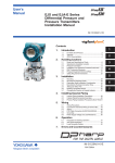
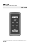
The following picture shows the items included in the FSA120 package.
FieldMate (bundled)
Disc No.1
Disc No.2
License Sheet No.1
Document No.1 and No.2
CD-ROM
DVD-ROM
License Number
Sheet
Paper Document
FieldMate
Device Files
FieldMate
FieldMate
FlowNavigator
Disc No.3
License Sheet No.2
Document No.3 and No.4
CD-ROM
License Number
Sheet
Paper Document
FlowNavigator
FlowNavigator
FlowNavigator
USB FieldMate Modem (Option)
FSA120
F01E.ai
Figure 2.1
Components of FSA120
Each disk contains the following software.
CD-ROM/DVD-ROM: 3 discs
(1) FieldMate <Disc No.1>
(2) Device Files (Includes Device DTM*) <Disc No.2>
*: Device DTM is delivered by Yokogawa DTMLibrary HART/FOUNDATION fieldbus
(3) FlowNavigator (Includes FlowNavigator Program and Resource) <Disc No.3>
License Sheet: 2 sheets
(1) FieldMate License Number Sheet (Basic or Advance, as specified in order)
<License Sheet No.1>
(2) FlowNavigator License Number Sheet <License Sheet No.2>
IM 01C25R51-01E
<2. General>
2-2
Paper Document: 4 sheets
(1)
FieldMate Getting Started (IM 01R01A04-01E) <Document No.1>
(2)
FieldMate Operational Precaution (IM 01R01A01-91E) <Document No.2>
(3)
FlowNavigator Getting Started (IM 01C25R51-10E) <Document No.3>
(4)
FlowNavigator License Agreement <Document No.4>
USB FieldMate Modem (Option)
NOTE
For FSA120 R1.04 or later, the product name has been changed to “FieldMate FlowNavigator”
because the DYFMVTool program for digitalYEWFLO Vortex Flowmeter has been added.
Consequently, the following items have been renamed accordingly:
<Disc No.3>:
EJXMVTool Additional resource disk → FlowNavigator CD-ROM
<License Sheet No.2>:
EJXMVTool License Number Sheet → FlowNavigator License Number Sheet
<Document No.3>:
EJXMVTool Read Me First → FlowNavigator Getting Started
<Document No.4>:
EJXMVTool License Agreement → FlowNavigator License Agreement.
NOTE
The location of following software has been changed for FSA120 R1.04 or later.
• Device Files DVD-ROM <Disc No.2>:
FlowNavigator program has been moved from Yokogawa DTMLibrary HART/FOUNDATION
fieldbus in Device Files DVD-ROM to FlowNavigator CD-ROM
• FlowNavigator CD-ROM <Disc No.3>:
In addition to Resource, the FlowNavigator program (EJXMVTool and DYFMVTool) has been
added.
IM 01C25R51-01E
2.2
1)
2-3
<2. General>
To Start with
FlowNavigator is the software utilizing FDT/DTM technology. To use this software, a frame
application is required. ‘Field Mate’ is bundled with this software package as Yokogawa
standard frame application. The quality and operability of FlowNavigator is certified for use
with FieldMate only. Please use ‘Field Mate’ as frame application.
Also, you can use Field communication server included in FieldMate as a Communication
DTM. For the installation and operation of FieldMate, please refer to the printed document.
• “FieldMate Getting Started” (IM 01R01A04-01E) <Document No.1>
• “FieldMate Operational Precaution” (IM 01R01A01-91E) <Document No.2>
For the details of installation and operation, please also refer to the user’s manual of
FieldMate in pdf format shown by start menu.
2)
Before starting any operation, please carefully read the instructions in the user’s manual
of FlowNavigator and obtain necessary knowledge about installation and operation of the
software.
The User’s manual “FSA120 Flow Configuration Software” (IM 01C25R51-01E) is provided
as a Portable Document Format (pdf) file in the CD-ROM labeled “FlowNavigator”, and is
located at
<FlowNavigator CD-ROM>: \EJXMVTool_Manual.pdf
<FlowNavigator CD-ROM>: \DYFMVTool_Manual.pdf
Set the FlowNavigator CD-ROM in the CD-ROM drive of your computer and double click the
name of the file.
To read the file in PDF format, Adobe Reader is required.
If Adobe Reader is not on your PC, download and install Adobe Reader from the following
website.
<http://www.adobe.com/>
IM 01C25R51-01E
2.3
<2. General>
2-4
Installation Flow
Followings are the flow of standard installation. As the procedures may differ according to the
condition, please find details in each designated manual and follow the instructions.
Step 1
Confirm incompatible software does not exist, PRM and FSA210 .
(Refer to <Document No.2>)
Step 2
Install communication device software (For FOUNDATION fieldbus
communication)
Step 3
Install FieldMate (Refer to <Document No.1>)
1) Install FieldMate <Disc No.1>
2) Enter the license number of FieldMate <License Sheet No.1>
3) Install Device Files <Disc No.2>
Step 4
Install FlowNavigator <Disc No.3>
Step 5
Start FieldMate
1) Register yourself in FieldMate (Refer to <Document No.1>)
2) Start Device DTM
Step 6
Start FlowNavigator Program
1) Enter the license number of FlowNavigator <License Sheet No.2>
IM 01C25R51-01E
2.4
2-5
<2. General>
Outline of FlowNavigator
The FSA120 (FieldMate FlowNavigator) is the software package which offers various functions to
help users to easily configure the mass flow parameters of device.
The FSA120 includes following two programs:
• EJXMVTool: for EJX Multivariable Transmitter
• DYFMVTool: for digitalYEWFLO Vortex Flowmeter
FSA120 includes FieldMate, Yokogawa’s frame application. It employs FDT/DTM technology and
works on the FieldMate.
FSA120 has the following features:
• Easy flow parameter configuration by dialog windows
• Configuration of the fluid physical properties*
*: DIPPR, Steam tables IAPWS-IF97, Natural gas standard AGA8/ISO12213
• Configuration of the primary device**
**: Orifice, Nozzle, Venturi, FIX
• Various flow calculation modes
EJXMVTool: Auto Compensation Mode / Basic Mode
DYFMVTool: Detail Compensation Mode / Steam Mode / Simple Mode
• HART and FOUNDATION fieldbus H1 are supported.
FSA120 provides the following advantages to device:
• Highly-responsive flow measurement and saving cost by built-in flow computer inside
device
• Highly-accurate mass flow rate output compensated by process temperature or pressure
value by using the fluid physical properties database
• Easy mass flow configuration by FDT/DTM standard conforming software
FieldMate: Yokogawa’s frame application which conforms to FDT standard
FDT(Field Device Tool): defines the system environment in which the DTM runs.
DTM(Device Type Manager): the application which defines the graphical user interface(GUI) specific to the device.
NOTE
For FSA120 R1.03 or before, FSA120 was called “EJXMVTool(EJX-MV Configuration DTM)”
because it comprised a single EJXMVTool program for the EJX Multivariable Transmitter.
For FSA120 R1.04 or later, the product name has been changed to “FieldMate FlowNavigator
(Flow Configuration Software)” because the DYFMVTool program for digitalYEWFLO Vortex
Flowmeter has been added.
IM 01C25R51-01E
2-6
<2. General>
FlowNavigator consists of two programs (EJXMVTool and DYFMVTool) and Resource
(Instruction Manual and Database) for both programs.
To perform the flow configuration of EJX Multivariable Transmitter, use FlowNavigator program,
EJXMVTool, which works on Device DTM, EJX910 HART/FOUNDATION fieldbus DTM.
EJXMVTool consists of the Flow Configuration Wizard, a dialog editor for flow configuration, and
Obtain Flow Coefficient, a display for confirming the flow configuration.
To perform the flow configuration of digitalYEWFLO Vortex Flowmeter, use FlowNavigator
program, DYFMVTool, which works on Device DTM, DYF(SoftDL) FOUNDATION fieldbus DTM.
DYFMVTool consists of the Flow Configuration Wizard, a dialog editor for flow configuration.
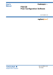
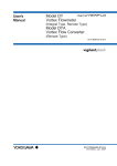
The following charts show a configuration consisting of a notebook PC, communication device
and EJX Multivariable Transmitters and digitalYEWFLO Vortex Flowmeter.
FieldMate (Versatile Device Management Wizard)
FlowNavigator(Flow Configuration Software)
Resource
Database
Instruction Manual
Program
EJXMVTool
DYFMVTool
EJX910 HART/
FOUNDATION fieldbus DTM
DYF(SoftDL)
FOUNDATION fieldbus DTM
Device DTM (Device Management)
Communication DTM
Notebook PC
USB Port / PCMCIA Card Slot
Communication Device (HART, FOUNDATION fieldbus)
HART Communication /
FOUNDATION fieldbus-H1 Communication
EJX Multivariable Transmitter
digitalYEWFLO Vortex Flowmeter
F0202E.ai
Figure 2.2a
Functional diagram
IM 01C25R51-01E
2-7
<2. General>
FlowNavigator Resource
<License required>
Database
Physical Properties
Database
Primary Device
Information
(Only EJXMVTool)
Fluid Information
Operating Conditions
Instruction Manual
FlowNavigator
F0203E.ai
Figure 2.2b
FlowNavigator Resource
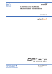
EJXMVTool
(Flow Parameter Management)
<License required>
EJX910 HART/FOUNDATION fieldbus DTM
(Device Management)
Obtain Flow Coefficient
Flow Configuration Wizard
Offline Parameters
Online Parameters
Dialog Editor
Dialog Editor
Dialog Editor
Dialog Editor
Sensor mode
Auto / Basic
Compensation Mode
Tag
Tag
Range
Range
Unit
Unit
Damping
Damping
Lowcut
Lowcut
Simulation mode
Calculation of flow
parameters
File Management
Adjustment
Report
Download to /
Upload from
Device
Monitoring
Process Value
F0204E.ai
Figure 2.2c
FlowNavigator Program and Device DTM (EJX Multivariable Transmitter)
IM 01C25R51-01E
2-8
<2. General>
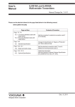
DYFMVTool
(Flow Parameter Management)
<License required>
DYF(SoftDL) FOUNDATION fieldbus DTM
(Device Management)
Flow Configuration Wizard
Offline Parameters
Online Parameters
Dialog Editor
Dialog Editor
Dialog Editor
Detail / Steam, Simple
Compensation Mode
Tag
Tag
Range
Range
Unit
Unit
Damping
Damping
Lowcut
Lowcut
Calculation of Flow Parameters
File Management
Adjustment
Report
Download to /
Upload from
Device
Monitoring
Process Value
F0205E.ai
Figure 2.2d
FlowNavigator Program and Device DTM (digitalYEWFLO Vortex Flowmeter)
IM 01C25R51-01E
2.5
2-9
<2. General>
FlowNavigator Programs
FlowNavigator and Device DTM consist of following programs.
Each program can be started in the following way.
• Execute Device DTM on the FieldMate*.
(Not necessary to enter a license for FlowNavigator)
• Execute the FlowNavigator Program on Device DTM.
(Necessary to enter your license for FlowNavigator)
*: Device DTM function is operated by DTMWorks
Table 2.1
Function of FlowNavigator Resource
Program
FlowNavigator Resource
Table 2.2
Function
Contents
Install location
Database
Database
• Physical property
database used for flow
parameter calculation
–
Instruction
Manual
Instruction
Manual
• FlowNavigator
Instruction Manual
<DTM InstDrive>:
\Program Files
\Yokogawa\DTMs
\MVToolCommon
Startup
method
–
License
Required
Function of EJXMVTool (for HART communication) and EJX910 HART DTM
Program
Device DTM
EJX910
HART DTM
Flow
Navigator
Program
-EJXMVTool-
Function
Device
Management
Contents
Install location
Startup
License
method
• Online Parameter
• Offline Parameter
• Download to or Upload
from the device
<DTM InstDrive>:
\Program Files
\Yokogawa\DTMs
Execute
from
FieldMate
Not
required
Flow
Flow
Configuration Parameter
Wizard
Management
-Flow
Configuration-
• Configuration of
flow parameters for
EJX Multivariable
Transmitter
- Auto Compensation
Mode
- Basic Mode
• File management
• Report function
<DTM InstDrive>:
\Program Files
\Yokogawa\DTMs
\EJXMVTool
Execute
from
EJX910
HART
DTM
Required
Obtain Flow
Coefficient
• Flow coefficient
retrieval
Flow
Parameter
Management
-Confirming
Flow
Configuration-
Required
IM 01C25R51-01E
2-10
<2. General>
Table 2.3
Function of EJXMVTool (for FOUNDATION fieldbus communication) and EJX910 FOUNDATION
fieldbus DTM
Program
Function
Startup
method
License
Execute
from
FieldMate
Flow
Flow
Configuration Parameter
Wizard
Management
-Flow
Configuration-
• Configuration of
flow parameters for
EJX Multivariable
Transmitter
- Auto Compensation
Mode
- Basic Mode
• File management
• Report function
Execute
Required
from
EJX910
FOUNDATION
fieldbus
DTM
Obtain Flow
Coefficient
• Flow coefficient
retrieval
EJX910
FOUNDATION fieldbus DTM
Flow
Navigator
Program
-EJXMVTool-
Table 2.4
Install location
• Online Parameter
<DTM InstDrive>:
• Offline Parameter
\Program Files
• Download to or Upload \Yokogawa\DTMs
from the device
Device DTM
Device
Management
Contents
Flow
Parameter
Management
-Confirming
Flow
Configuration-
<DTM InstDrive>:
\Program Files
\Yokogawa\DTMs
\YokFFFramework
\EJXMVToolFF
Not
required
Required
Function of DYFMVTool (for F OUNDATION fieldbus communication) and DYF(SoftDL)
FOUNDATION fieldbus DTM
Program
Function
Device
Management
Device DTM
DYF(SoftDL)
FOUNDATION fieldbus DTM
Flow
Navigator
Flow
Program
Flow
-DYFMVTool- Configuration Parameter
Wizard
Management
-Flow
Configuration-
Contents
Install location
Startup
method
License
• Online Parameter
<DTM InstDrive>:
• Offline Parameter
\Program Files
• Download to or Upload \Yokogawa\DTMs
from the device
Execute
from
FieldMate
• Configuration of flow
parameters for DYF
- Detail
Compensation Mode
- Steam, Simple
Compensation Mode
• File management
• Report function
Execute
Required
from
DYF
(SoftDL)
FOUNDATION
fieldbus
DTM
<DTM InstDrive>:
\Program Files
\Yokogawa\DTMs
\YokFFFramework
\DYFMVToolFF
Not
required
IM 01C25R51-01E
3-1
<3. Functional Specification>
3.
Functional Specification
3.1
PC
3.1.1
Hardware Operating Environment
Hardware Operating Environment
PC
CPU
Main Memory
Hard Disk Drive
CD-ROM Drive
Display
Network port
HART
FOUNDATION fieldbus H1
Windows 7
Windows Vista
IBM PC/AT Compatible
Intel® CoreTM2 Duo T7100 or similar specification CPU
1GB or more
2GB or more
(2GB or more recommended)
8GB or more
Windows 7 compatible
Windows Vista compatible
1024×768 or better resolution
1024×768 or better resolution
recommended
recommended
Windows 7 compatible
Windows Vista compatible
One USB port USB2.0 standard / Bluetooth 2.0
One PCMCIA card slot / One USB port USB2.0 standard
IM 01C25R51-01E
3.1.2
3-2
<3. Functional Specification>
Software Operating Environment
• Windows 7 Professional 32bit / 64bit / Home Premium 32bit / 64bit SP1 or later (English)
• Windows Vista business 32bit SP2 or later (English)
IMPORTANT
Login Windows as an Administrator or a user with an administrative authority.
The following software is necessary to be installed in your computer.
Common
Adobe Reader
FDT frame application conforming to FDT Interface Specification Version 1.2
The frame application which is already tested with FSA120 and proper operation is
confirmed; FieldMate
For HART Communication
Communication DTM for HART Modem conformed FDT Interface Specification Version 1.2
The following Communication DTM has been tested with FSA120 and compatibility is
confirmed; HART Communication DTM included in FieldMate
For FOUNDATION fieldbus Communication
Communication DTM for PCMCIA-FBUS conforming to FDT version 1.2
The following Communication DTM has been tested with FSA120 and compatibility is
confirmed; FOUNDATION fieldbus communication DTM included in FieldMate.
NI-FBUS Communications Manager
• Windows Vista, Windows 7: 4.0.1 or later
Function Block Scheduling and Connection Tool (For DYFMVTool)
e.g.NI-FBUS Configurator
• Windows Vista, Windows 7: 4.0.1 or later
NOTE
Install the following software which is contained in FSA120.
1) FieldMate
•FDT frame application
•HART communication DTM
•FOUNDATION fieldbus communication DTM
2) Device Files
•EJX910 HART DTM (included in Yokogawa DTM Library HART)
•EJX910 FOUNDATION fieldbus DTM (included in Yokogawa DTM Library FOUNDATION
fieldbus)
•DYF(SoftDL) FOUNDATION fieldbus DTM (included in Yokogawa DTMLibrary FOUNDATION
fieldbus)
IMPORTANT
If you already have FSA210 Mass Flow Configuration Software installed in your computer,
uninstall FSA210 to avoid the competition of COM PORT.
IM 01C25R51-01E
3.2
<3. Functional Specification>
Field Communication
1)
HART communication
Recommended HART modem:
USB FieldMate Modem: BRAIN/HART (Optional code: /B, Yokogawa Parts Number:
F9197UC)
VIATOR® Bluetooth® Interface: Model 010041 (MACTek®) *
2)
FOUNDATION fieldbus communication
Recommended:
Softing
3.3
3-3
FFusb**
National Instruments
PCMCIA-FBUS Series 2
NI USB-8486
* : Microsoft supplied Bluetooth stack is used.
**: The package is provided complete with FieldMate driver from Softing.
Model to be Connected
• EJX Multivariable Transmitter
EJX910A/EJX930A
Protocol: HART, FOUNDATION fieldbus
• digitalYEWFLO Vortex Flowmeter
DY-F/DYA-F
Protocol: FOUNDATION fieldbus
Device Type: 9, Device revision: 3 or later
IM 01C25R51-01E
3-4
<3. Functional Specification>
3.4
Function Detail
3.4.1
Device Management
Device Management function is supported by EJX910 HART/FOUNDATION fieldbus and
DYF(SoftDL) FOUNDATION fieldbus DTM.
FOUNDATION fieldbus Device DTM supports following blocks.
EJX910 FOUNDATION fieldbus DTM:
Resource block, Sensor Transducer block, Flow Transducer block, LCD Transducer block,
and AI function blocks
DYF(SoftDL) FOUNDATION fieldbus DTM:
Resource block, Transducer block, AI function blocks and AR function block
Parameters of other function blocks should be set and changed by other Fieldbus configurators.
IMPORTANT
Use function block scheduling and connection tool for DYFMVTool. After using these setting tool,
finish the program before starting FlowNavigator.
(1) Online Parameter
The Device General Parameters of the device can be edited directly in online status.
(Tag, Range, Unit, Damping, Lowcut, Indicator display)
(2) Offline Parameter
The Device General Parameters of the device can be edited and stored in offline database.
(Process value monitoring, Tag, Range, Unit, Damping, Lowcut, Indicator display)
(3) Downloads to or uploads from the device
The Device Flow Parameters and Device General Parameters stored in offline database are
downloaded to the device.
The parameters of the device is uploaded from the device and stored in offline database.
Device General Parameters:
HART or FOUNDATION fieldbus parameters of the device, which can be modified with using
Device DTM. e.g. range, damping, etc.
User Flow Parameters:
The parameters which users input on EJXMVTool and DYFMVTool for flow configuration.
These parameters are used to only generate Device Flow Parameters and not downloaded to
the device.
Device Flow Parameters:
The parameters which EJXMVTool and DYFMVTool calculate and generate with using the User
Flow Parameters and are downloaded to the device.
IM 01C25R51-01E
3.4.2
3-5
<3. Functional Specification>
Flow Parameter Management (Flow Configuration
Wizard)
(1) EJXMVTool
(a) Auto Compensation Mode
Configuration of the fluid physical properties and primary device for the EJX
Multivariable Transmitter can be performed using a dialog window. Refer to Section 7.1.
(b) Basic Mode
Flow operation and density compensation are performed conventionally, with the flow
factors being input manually. Refer to Section 7.2.
(c) File management
Parameters are imported and exported using following files.
xmv file: import / export User Flow Parameters and Device Flow Parameters
prm file: Import HART Device Flow Parameters (only for FSA210 user)
(d) Report function
Export User Flow Parameters and Device General Parameters in CSV file format.
(2) DYFMVTool
(a) Detail (Gas / Liquid) Compensation Mode
Configuration of the fluid physical properties for the digitalYEWFLO Vortex Flowmeter
can be performed using a dialog window. Refer to Section 8.1.
(b) Steam Compensation Mode
Flow operation and density compensation are performed, with the flow factors inside
digitalYEWFLO Vortex Flowmeter. Refer to Section 8.2.
(c) Simple (Gas / Liquid) Compensation Mode
Flow operation and density compensation are performed conventionally, with the flow
factors being input manually. Refer to Section 8.2.
(d) File management
Parameters are imported and exported using following files.
vmv file: import / export User Flow Parameters and Device Flow Parameters
(e) Report function
Export User Flow Parameters and Device General Parameters in CSV file format.
IM 01C25R51-01E
3-6
<3. Functional Specification>
3.4.3
Flow Parameter Management (Obtain Flow Coefficient)
This function is supported by EJXMVTool.
Flow coefficient retrieval
The flow coefficient can be obtained from the device (input selection: sensor data or
simulated data).
3.4.4
Primary Device
This function is supported by EJXMVTool Auto Compensation Mode.
Table 3.1
Type
Orifice
Nozzle
Venturi
FIX
Supported primary devices
Primary Device
Orifice Corner Taps [ISO5167-1 1991]
Orifice Corner Taps [ISO5167-2 2003]
Orifice Corner Taps [ASME MFC-3M 1989]
Orifice Flange Taps [ISO5167-1 1991]
Orifice Flange Taps [ISO5167-2 2003]
Orifice Flange Taps [ASME MFC-3M 1989]
Orifice Flange Taps [AGA No.3 1992]
Orifice D and D/2 Taps [ISO5167-1 1991]
Orifice D and D/2 Taps [ISO5167-2 2003]
Orifice D and D/2 Taps [ASME MFC-3M 1989]
ISA1932 nozzle [ISO5167-1 1991/ ISO5167-3 2003]
Long radius nozzle [ISO5167-1 1991/ ISO5167-3 2003]
ASME FLOW NOZZLES [ASME MFC-3M 1989]
Venturi nozzle [ISO5167-1 1991/ ISO5167-3 2003]
Classical Venturi tube “as cast” convergent section [ISO5167-1 1991/ ISO5167-4 2003]
ASME Venturi Tubes With a rough Cast or Fabricated Convergent [ASME MFC-3M 1989]
Classical Venturi tube with a machined convergent section [ISO5167-1 1991/ ISO5167-4 2003]
ASME Venturi Tubes With a machined convergent section [ASME MFC-3M 1989]
Classical Venturi tube with a rough-welded sheet-iron convergent section
[ISO5167-1 1991/ ISO5167-4 2003]
Fixed Mode (Sets the discharge coefficient and gas expansion factor to a fixed value)
IM 01C25R51-01E
3.4.5
3-7
<3. Functional Specification>
Density Compensation
This function is supported by EJXMVTool Auto Compensation Mode and DYFMVTool Detail
(Gas/Liquid) Compensation Mode.
(1) Density compensation using physical properties database
Table 3.2
Supported physical properties database
Fluid name
Acetic Acid (*)
Acetone
Acetonitrile
Acetylene
Acrylonitrile
Air
Allyl Alcohol
Ammonia
Argon
Benzaldehyde
Benzene
Benzoic Acid (*)
Benz Alcohol
Biphenyl
Bromine
Carbon Dioxide
Carbon Monoxide
Carbon Tetrachloride
Chlorine
Chlorodifluoromethane
Chloroprene
Chlorotrifluoroethylene
Cycloheptane
Cyclohexane
Cyclopentane
Cyclopentene
Cyclopropane
Dichlorodifluoromethane
Divinyl Ether
Ethane
Ethanol
Ethylamine
Ethylbenzene
Ethylene
Ethylene Glycol
Ethylene Oxide
Fluorene
Furan
Helium-4
Hydrazine
Hydrogen
Hydrogen Chloride
Hydrogen Cyanide
Hydrogen Peroxide
Hydrogen Sulfide
Fluid name
Isobutane
Isobutene
Isobutylbenzene
Isopentane
Isoprene
Isopropanol
m-chloronitrobenzene
m-dichlorobenzene
Methane
Methanol
Methyl Acrylate
Methyl Ethyl Ketone
Methyl Vinyl ether
Monochlorobenzene
n-Butane
n-Butanol
n-Butyraldehyde
n-Butyronitrile
n-Decane
n-Dodecane
n-Heptadecane
n-Heptane
n-Hexane
n-nonane
n-Octane
n-Pentane
Neon
Neopentane
Nitric Acid (*)
Nitric Oxide
Nitrobenzene
Nitroethane
Nitrogen
Nitromethane
Nitrous Oxide
Oxygen
Pentafluoroethane
Phenol
Phosphoric Acid (*)
Propadiene
Propane
Propylene
Pyrene
Styrene
Sulfur Dioxide
Fluid name
Toluene
Trichloroethylene
Trichlorofluoromethane
Vinyl Acetate
Vinyl Chloride
Vinyl Cyclohexene
Water
1-Butene
1-Decene
1-Decanal
1-Decanol
1-Dodecene
1-Dodecanol
1-Heptanol
1-Heptene
1-Hexene
1-Hexadecanol
1-Octanol
1-Octene
1-Nonanal
1-Nonanol
1-Pentadecanol
1-Pentanol
1-Pentene
1-Undecanol
1,1,2,2-Tetrafluoroethane
1,1,2-Trichloroethane
1,2,4-Trichlorobenzene
1,2-Butadiene
1,3-Butadiene
1,3,5-Trichlorobenzene
1,4-Dioxane
1,4-Hexadiene
2-Methyl-1-Pentene
2,2-Dimethylbutane
*: Only for liquid.
IM 01C25R51-01E
3-8
<3. Functional Specification>
Source:
DIPPR® Project No.801 Database 2003 Edition
This Physical Property Database from American Institute of Chemical Engineers (AIChE®)
NOTE
The DIPPR recommends an air temperature no higher than –25°C and cannot guarantee results
if this temperature limit is exceeded.
(2) Density compensation using standard steam tables (For EJXMVTool)
IAPWS-IF97 Water and Steam (1997)
IAPWS-IF97: IAPWS Industrial Formulation 1997
IAPWS: The International Association for the Properties of Water and Steam
(3) Density compensation using standard.
Natural gas:
AGA8.
Compressibility Factors of Natural Gas and Other Related Hydrocarbon Gases
American Gas Association (AGA)
Transmission Measurement Committee Report No.8 Second Edition, November 1992
Detail Characterization Method
Gross Characterization Method 1
Gross Characterization Method 2
ISO 12213:1997 First edition 1997-12-01
Part 2: molar-composition analysis
Part 3: physical properties
(4) Custom fluid density and viscosity compensation
Numerical value user input for physical properties (density, viscosity, etc.)
IM 01C25R51-01E
<4. Preparation>
4.
Preparation
4.1
PC
4-1
To ensure that FlowNavigator functions properly, please make sure your PC meets the
requirements stated in the section ‘3.1’.
All application must be finished.
4.1.1
Setting Items after Installing Windows
It is recommended that the following items be set and confirmed before installation of
FlowNavigator.
● Power Management
FieldMate may not function properly while the sleep, standby and hibernation settings are
enabled. The settings above can be disabled in Windows. The setting procedure is as follows.
<Windows 7>
Log on as a user with administrator privileges, click the Start menu, select Control Panel,
Hardware and Sound, double-click Power Options to display the Power Options Properties dialog
box, and then make sure the following items are set as described below. Note that some of the
items described below may not be displayed depending on the configuration of the PC.
If an item is not displayed, the function is disabled.
• Choose what the power button does.
When I press the power button: Do nothing
When I close the lid: Do nothing
• Choose what to turn off the display
Turn off the display: Never
<Windows Vista>
Log on as a user with administrator privileges, click the Start menu, select Control Panel, doubleclick Power Options to display the Power Options Properties dialog box, and then make sure the
following items are set as described below. Note that some of the items described below may not
be displayed depending on the configuration of the PC. If an item is not displayed, the function is
disabled.
• System Settings window
When I press the power button: Do nothing
When I press the sleep button: Do nothing
When I close the lid: Do nothing
• Edit Plan Settings window
Put the computer to sleep: Never
IM 01C25R51-01E
4-2
<4. Preparation>
4.2
Installation Procedure
4.2.1
Online Manual
The pdf format Manual for FlowNavigator is located at
<FlowNavigator CD-ROM>: \EJXMVTool_Manual.pdf
<FlowNavigator CD-ROM>: \DYFMVTool_Manual.pdf
If Adobe Reader is not on your PC, download and install it from the following website.
4.2.2
<http://www.adobe.com/>
Uninstall FSA210
This procedures are only applicable for the users of FSA210 Mass Flow Configuration Software.
If FSA210 is existing on your PC, uninstall it to avoid the competition with FieldMate.
To uninstall all the program of FSA210, take the following three steps.
(1) Uninstall a field communication server
Execute <FieldInstDrive>: \PRM\Program\PRMUninstall.exe
Double-click the filename in Windows Explorer.
<FieldInstDrive> is the drive on which field communication server is installed.
<FieldInstDrive> is the drive where the PRM directory is located.
The default drive is the same drive on which Windows is installed.
(2) Uninstall the EJXMVTool program with the Add or Remove Programs function of the
Windows Control Panel. Select EJXMVTool and click [Change/Remove].
(3) Uninstall Exaopc
Use the Add or Remove Programs function of the Windows Control Panel to uninstall
Exaopc. Select Exaopc and click [Change/Remove].
Follow the instruction to reboot the computer.
NOTE
Refer to Appendix A for the detailed procedures of uninstalling FSA210.
IM 01C25R51-01E
4-3
<4. Preparation>
4.2.3
For FieldMate Users
If you already have FieldMate installed in your computer, which satisfies the operating
requirement of FlowNavigator, you may need to skip the installation of FieldMate. Please see the
followings.
NOTE
If FieldMate installed in your PC is older version and does not satisfy the working condition of
FlowNavigator, it is necessary to install FieldMate which satisfies the requirement.
NOTE
FlowNavigator requires “Device Files R3.03.00 or later”. Device Files R3.03.00 includes
“DTMLibrary FOUNDATION fieldbus 2011-4” and “DTMLibrary HART 2011-3”.
If Device Files installed in your PC does not satisfy the above condition, it is necessary to install
the FieldMate and Device Files which are bundled in FSA120.
1) If you have FieldMate Basic installed on your PC, and...
• if you have purchased FSA120 with FieldMate Basic;
check the version of FieldMate which is installed on your PC.
On the other hand, the version of the bundled FieldMate is shown on the disk.
If the version is lower than that of the bundled FieldMate, install the bundled FIeldMate.
If the version is equivalent or higher, install FlowNavigator CD-ROM alone.
• if you have purchased FSA120 with FieldMate Advance;
install the bundled FieldMate Advance and FlowNavigator CD-ROM.
2) If you have FieldMate Advance installed on your PC, and...
• if you have purchased FSA120 with FieldMate Basic;
check the version of FieldMate which is installed on your PC.
On the other hand, the version of the bundled Fieldmate is shown on the disk.
If the version is lower than that oh the bundled FieldMate, install the bundled FieldMate
Basic after uninstalling the previous version of FieldMate Advance.
If the version is equivalent or higher, install FlowNavigator CD-ROM alone.
• if you have purchased FSA120 with FieldMate Advance;
check the version of FieldMate which is installed on your PC.
On the other hand, the version of the bundled FieldMate is shown on the disk.
If the version is lower than that of the bundled FieldMate, install the bundled FIeldMate.
if the version is equivalent or higher, install FlowNavigator CD-ROM alone.
IM 01C25R51-01E
4.2.4
4-4
<4. Preparation>
FieldMate and Device Files Installation
Install following software before installing FlowNavigator.
Step 1
Install software for communication device (For F OUNDATION fieldbus
communication)
Refer to Appendix D-1 for detail.
Step 2
Install FieldMate
NOTE
Device Files which includes Yokogawa DTMLibrary HART/FOUNDATION fieldbus and software for
HART communication device are automatically installed during the installation of FieldMate.
Regarding installation of software for HART communication device, refer to Appendix C-1.
NOTE
For the installation procedures of FieldMate, refer to the User’s Manual IM01R01A04-01E
“FieldMate Versatile Device Management Wizard Getting Started”.
When installing FieldMate, log-in the Windows as an Administrator or an user with an
administrative authority.
4.2.5
FlowNavigator Installation
Following gives the overview of FlowNavigator Setup and recommended installation procedures.
Overview of FlowNavigator Setup
The FlowNavigator setup is used for installing FlowNavigator (FOUNDATION fieldbus Program,
HART Program and Resource) and located in “FlowNavigator CD-ROM”.
Following shows “FlowNavigator Setup window”.
Install FlowNavigator for both HART and
FOUNDATION fieldbus
[FlowNavigator]
Install FlowNavigator for HART
[FlowNavigator HART]
Install FlowNavigator for FOUNDATION
fieldbus
[FlowNavigator FOUNDATION fieldbus]
F0401E.ai
Figure 4.1
FlowNavigator Setup window
IM 01C25R51-01E
4-5
<4. Preparation>
Following gives FlowNavigator Software Component assigned to FlowNavigator setup window
button.
Table 4.1
Assignment of FlowNavigator setup window button
FlowNavigator
Software Component
FOUNDATION fieldbus Program *1
(EJXMVTool FOUNDATION fieldbus
and DYFMVTool FOUNDATION
fieldbus)
HART Program *2
(EJXMVTool HART)
Resource *3
(Database and Instruction manual)
FlowNavigator setup window button
Recommended
Custom
[FlowNavigator
[FlowNavigator]
[FlowNavigator HART]
FOUNDATION fieldbus]
Installed
Not installed
Installed
Installed
Installed
Not installed
Installed
Installed
Installed
*1: Installed by “FlowNavigator FOUNDATION fieldbus program” Upgrade Setup. For detail,
refer to “Installation Procedure <Step 3>”.
*2: Installed by “FlowNavigator HART program” Upgrade Setup. For detail, refer to “Installation Procedure <Step 4>”.
*3: Installed by “FlowNavigator Resource” Setup. For detail, refer to “Installation Procedure <Step 5>”.
Installation Procedure
Following gives the FlowNavigator recommended installation procedures.
IMPORTANT
The quality, operability of FlowNavigator is certified for use with FieldMate only.
Step 1
Login Windows
Login Windows as an Administrator or a user with an administrative authority.
Step 2
Insert the “FlowNavigator CD-ROM”
Insert the “FlowNavigator CD-ROM” into the CD-ROM drive. Auto run starts and a FlowNavigator
setup window appears. And click [FlowNavigator].
Figure 4.2
FlowNavigator Setup window
IM 01C25R51-01E
4-6
<4. Preparation>
IMPORTANT
If auto run does not start after inserting the CD-ROM, double-click the following file.
<FlowNavigator CD-ROM>:\FlowNavigator.exe
NOTE
On Windows Vista/Windows 7, due to user account control, the “Auto Play” or “User Account
Control” window may be displayed. And confirmation operation is required.
Step 3
“FlowNavigator FOUNDATION fieldbus program” Upgrade Setup window appears
NOTE
“FlowNavigator FOUNDATION fieldbus program” Upgrade Setup installs EJXMVTool FOUNDATION
fieldbus and DYFMVTool FOUNDATION fieldbus.
The setup requires “DTMLibrary FOUNDATION fieldbus 2011-4 or later”. Device Files R3.03.00
includes “DTMLibrary FOUNDATION fieldbus 2011-4” and “DTMLibrary HART 2011-3”.
(1) Click [Next].
Figure 4.3
Welcome screen
NOTE
In case of an error occurrence or cancellation during the installation of “FlowNavigator
FOUNDATION fieldbus program” Upgrade Setup, the following setup window appears.
• “FlowNavigator HART program” Upgrade Setup (“Installation Procedure <Step 4>”)
Then cancel the setup (If not canceled, the setup is installed).
After that, the following setup window appears sequentially.
• “FlowNavigator Resource” Setup (“Installation Procedure <Step 5>”)
Then cancel the setup (If not canceled, the setup is installed).
IM 01C25R51-01E
4-7
<4. Preparation>
NOTE
If following error message is shown, cancel the HART program setup and Resource setup.
Then install the FieldMate and Device Files which are bundled in FSA120 (refer to section 4.2.4),
and install FlowNavigator again.
Error message:
“Please check that the following files are installed in your PC. Yokogawa DTMLibrary
FOUNDATION fieldbus 2011-4 or later”
Figure 4.4 “DTMLibrary FOUNDATION fieldbus 2011-4 or later” nonexistence error message
The cause of error:
• Device Files is not installed
• The Device Files installed in your PC is R3.02.10 or before
(2) Select [I accept...] and click [Next].
Figure 4.5
License Agreement screen
NOTE
Print function is not supported.
The “License Agreement” paper is included in FSA120 package.
IM 01C25R51-01E
<4. Preparation>
4-8
(3) Input “User Name”, “Organization” and click [Next].
Figure 4.6
Customer Information screen
(4) Select [Automatic Upgrade].
[Custom Upgrade] setup is not supported.
Figure 4.7
Choose Upgrade Type screen
IM 01C25R51-01E
<4. Preparation>
4-9
(5) Click [Install].
Figure 4.8
Ready to Install screen
(6) Click [Finish]
Figure 4.9
Finish Setup screen
NOTE
Even though “Please update the DTM catalog” message is shown, FlowNavigator installation
does not require “Update DTM catalog” operation.
IM 01C25R51-01E
4-10
<4. Preparation>
Step 4
FlowNavigator HART program Upgrade Setup window appears
NOTE
“FlowNavigator HART program” Upgrade Setup installs EJXMVTool HART. The setup requires
“DTMLibrary HART 2011-3 or later”.
(1) Click [Next].
Figure 4.10a Welcome screen
NOTE
In case of error occurrence or cancellation during the installation of “FlowNavigator HART
program” Upgrade Setup, the following setup window appears.
• “FlowNavigator Resource” Setup (“Installation Procedure <Step 5>”)
Then cancel the setup (If not canceled, the setup is installed.).
IM 01C25R51-01E
4-11
<4. Preparation>
NOTE
If following error message is shown, cancel Resource setup.
Then install the FieldMate and Device Files which are bundled in FSA120 (refer to section4.2.4),
and install FlowNavigator again.
Error message:
“Please check that the following files are installed in your PC. Yokogawa DTMLibrary
HART 2011-3/ HART 2011-3J or later”
Figure 4.10b “DTMLibrary HART 2011-3/ HART 2011-3J or later” nonexistence error message
The cause of error:
• Device Files is not installed
• The Device Files installed in your PC is R3.02.10 or before
(2) Select [I accept...] and click [Next].
Figure 4.11
End-User License Agreement screen
NOTE
Print function is not supported.
The “License Agreement” paper is included in FSA120 package.
IM 01C25R51-01E
<4. Preparation>
4-12
(3) Input “User Name”, “Organization” and click [Next].
Figure 4.12
Customer Information screen
(4) Select [Automatic Upgrade].
[Custom Upgrade] setup is not supported.
Figure 4.13
Choose Upgrade Type screen
IM 01C25R51-01E
<4. Preparation>
4-13
(5) Click [Install].
Figure 4.14
Ready to Install screen
(6) Click [Finish].
Figure 4.15
Finish Setup screen
NOTE
Even though “Please update the DTM catalog” message is shown, FlowNavigator installation
does not require “Update DTM catalog” operation.
IM 01C25R51-01E
<4. Preparation>
Step 5
4-14
“FlowNavigator Resource” Setup window appears
NOTE
“FlowNavigator Resource” Setup installs Database and Instruction Manual.
(1) Click [Next].
Figure 4.16a Welcome screen
NOTE
In case that “FlowNavigator Resource” is already installed, following window appears.
Click [Next].
Figure 4.16b Welcome screen
This case is no problem and installation can be continued.
Because this can occur in following procedure:
1) FlowNavigator installation is partly canceled
- “FlowNavigator HART/FOUNDATION fieldbus program” is canceled
- “FlowNavigator Resource” is not canceled and installed correctly
2) FlowNavigator is installed again
IM 01C25R51-01E
4-15
<4. Preparation>
(2) Select [I accept...] and click [Next].
Figure 4.17
End-User License Agreement screen
NOTE
In case that “FlowNavigator Resource” is already installed, above window does not appear.
NOTE
Print function is not supported.
The “License Agreement” paper is included in FSA120 package.
(3) Input “User Name”, “Organization” and click [Next].
Figure 4.18
Customer Information screen
NOTE
In case that “FlowNavigator Resource” is already installed, above window does not appear.
IM 01C25R51-01E
4-16
<4. Preparation>
(4) Select [Complete] or [Custom].
Complete setup is recommended.
Figure 4.19a Choose Setup Type screen
NOTE
In case that “FlowNavigator Resource” is already installed, following window appears.
Select [Repair].
Overwrite
“FlowNavigator Resource”
[Repair]
F0419bE.ai
Figure 4.19b Modify, Repair or Remove installation screen
IM 01C25R51-01E
<4. Preparation>
4-17
(5) Click [Install].
Figure 4.20
Ready to Install screen
(6) Click [Finish].
Figure 4.21
Finish Setup screen
NOTE
Even though “Please update the DTM catalog” message is shown, FlowNavigator installation
does not require “Update DTM catalog” operation.
IM 01C25R51-01E
4-18
<4. Preparation>
Step 6
FlowNavigator setup window appears
Click [EXIT].
Figure 4.22
4.2.6
FlowNavigator Setup window
How to confirm Version Number
1)
FlowNavigator Resource
The version number is displayed on the “Programs and Features” screen of Windows
Control Panel. Select Yokogawa FlowNavigator Resource.
Figure 4.23 Version Number of Yokogawa FlowNavigator Resource
NOTE
For FSA120 R1.03 or before, the Windows Control Panel displays “Yokogawa MVTool additional
resource,” not “Yokogawa FlowNavigator Resource,” on the “Programs and Features” screen.
IM 01C25R51-01E
4-19
<4. Preparation>
2)
FlowNavigator Program: EJXMVTool, DYFMVTool
The version number is displayed on the HELP screen.
Flow Configuration Wizard (EJXMVTool, DYFMVTool): Refer to 6.3.5
Obtain Flow Coefficient (EJXMVTool): Refer to 7.3
3)
Yokogawa DTMLibrary HART/FOUNDATION fieldbus
The version number is displayed on the “Programs and Features” screen of Windows
Control Panel.
Version number
(HART)
Version number
(FOUNDATION fieldbus)
F0424E.ai
Figure 4.24
Version Number of DTM Library
4)
Device DTM: EJX910 HART/FOUNDATION fieldbus DTM, DYF(SoftDL) FOUNDATION fieldbus
DTM
Refer to 4.6.2 or 6.2.5.
IM 01C25R51-01E
4.3
<4. Preparation>
4-20
Uninstallation
(1) FieldMate
Refer to User's manual IM01R01A01-00E.
(2) FlowNavigator
Use the “Programs and Features” screen of the Windows Control Panel.
Select Yokogawa FlowNavigator Resource and click [Uninstall].
Figure 4.25
Remove Yokogawa FlowNavigator Resource
NOTE
For FSA120 R1.03 or before, the Windows Control Panel displays “Yokogawa MVTool additional
resource,” not “Yokogawa FlowNavigator Resource,” on the “Programs and Features” screen.
IM 01C25R51-01E
4.4
4-21
<4. Preparation>
Initial Setting (HART Communication)
NOTE
Regarding start up procedure of the device, refer to following:
EJX Multivariable Transmitter: User’s Manual IM01C25R01-01E “EJX910A and EJX930A
Multivariable Transmitters”
4.4.1
Install Communication Device
Connect the HART communication modem to the PC’s COM port.
4.4.2
COM Port
Refer to Appendix C-2 for how to confirm COM Port.
4.4.3
Wiring
EJX910A
6833/<í
Power supply
+
–
HART modem
PULS
E
SUPPLY+
SUPP
LY
K
CHEC
ALARM
5L
Note PC
F00426E.ai
Figure 4.26
Connection of HART instruments
NOTE
When RTD is not connected to EJX Multivariable Transmitter, the setting is possible though
alarm 03 is displayed on the indicator.
4.4.4
Communication Setting
This subsection describes the procedures to change the communication related setting of
FieldMate. Please try these procedures after you start FieldMate and if you experience that
communication is not correctly established. Please refer to 4.6.2.
(1) Communication port setting on FieldMate
1. Click the [Tool] → [HART Modem Configuration..] at FieldMate window.
2. Select com port number.
3. Click the [OK] button.
IM 01C25R51-01E
4-22
<4. Preparation>
Figure 4.27
HART Modem configuration
Select COM port number.
F0428E.ai
Figure 4.28
COM port
Please refer to FieldMate User's manual for details.
(2) Communication address setting on FieldMate
In FieldMate, the default setting of maximum scan value of communication address is “0”.
If the transmitter’s address is other than “0”, FieldMate cannot distinguish the transmitter.
Therefore, the setting should be changed to the correct value.
1. Click the [Tool] → [HART Modem Configuration..] at FieldMate window.
2. Select address number.
3. Click the [OK] button.
Maximum value of communication
Address for scaning
F0429E.ai
Figure 4.29
Address Setting
Please refer to FieldMate for detail.
IM 01C25R51-01E
4.5
<4. Preparation>
4-23
Initial Setting (FOUNDATION fieldbus
Communication)
NOTE
Regarding start up procedure of the device, refer to following:
EJX Multivariable Transmitter: User’s Manual IM01C25R01-01E “EJX910A and EJX930A
Multivariable Transmitters”
digitalYEWFLO Vortex Flowmeter: Appendix B-1
4.5.1
Device
Address and Tags (PD Tag and VFD Tag) must be set in the device.
IMPORTANT
Use function block scheduling and connection tool for DYFMVTool. After using these setting tool,
finish the program before starting FlowNavigator.
4.5.2
Install Communication Device
Install the Communication Device on PC.
4.5.3
Communication Setting
Refer to Appendix D-2 for Communication Device Setting.
4.5.4
Connect the Device to the power supply
(1) For EJX Multivariable Transmitter
Refer to User’s manual IM 01C25 R03-01E “EJX910A and EJX930A Fieldbus
Communication Type.”
(2) For digitalYEWFLO Vortex Flowmeter
Refer to User’s manual IM 01F06F00-01E “Model DY Vortex Flowmeter, Model DYA Vortex
Flow Converter, Fieldbus Communication Type”
4.5.5
Connect the Device to the Segment
IM 01C25R51-01E
<4. Preparation>
4-24
CAUTION
FSA120 is the software tool which is purposed for the setup and maintenance. Do not try
connecting it to the device which is under actual operation in the process. Before connecting
communication device to the segment, make sure that the process which is controlled by the
segment is off-lined.
communication device
FOUNDATION
fieldbus Device
Terminator
+
Loop Power
Supply
+
*
−
* Across the FOUNDATION fieldbus device.
−
Terminator
F0430E.ai
Figure 4.30
Connection example for FOUNDATION fieldbus
IM 01C25R51-01E
4.6
4-25
<4. Preparation>
Start FDT Frame Application
This section describes the operation of DTM with using FieldMate.
For the detailed operation of FieldMate, refer to User's manual of FieldMate.
The procedure is described with EJX910 HART DTM as an example.
4.6.1
Update DTM Setup
After new DTM is installed, click “DTM Setup”, so as to confirm that the designated DTM is
correctly installed.
Click [Start] → [All Programs] → [YOKOGAWA FieldMate] → [Tools] → [DTM Setup]
4.6.2
Start FieldMate
Starting FieldMate by following operation.
Step 1
Click [Start] → [All Programs] → [YOKOGAWA FieldMate] → [FieldMate]
Figure 4.31a Start FieldMate
IM 01C25R51-01E
4-26
<4. Preparation>
Step 2
Select Default Scan Segment
Specify whether to automatically scan HART devices/Foundation Fieldbus H1 devices after
startup. Select [HART] or [FOUNDATION fieldbus] and click [OK].
Figure 4.31b Select HART/FOUNDATION fieldbus
NOTE
The software for the communication device starts automatically when [FOUNDATION fieldbus] is
selected at [FieldMate]. Refer to Appendix D-3 for how to start the software.
Step 3
FieldMate Segment Viewer window
Open Segment Viewer on FieldMate.
A device icon appears on the window if it is successful to connect to FieldMate. If not, “No device
found” message is shown on the window.
If a connected device icon does not appear, check that initial setting for communication is
correctly done. Refer to section 4.4 for HART and 4.5 for FOUNDATION fieldbus.
Figure 4.31c Segment Viewer
IM 01C25R51-01E
<4. Preparation>
4-27
NOTE
FlowNavigator works on following Device DTM.
Table 4.2 Device DTM Name (EJX910 HART DTM)
Device DTM
Name
Model Name
EJX910 V1.1
EJX910 V2.1
EJX910A
EJX930A
EJX910 V2.1*
EJX Multivariable Transmitter
HART Protocol
Device Type
Revision
EJX910
(0x0054)
5
EJX910
(0x0054)
7
EJX910
(0x3754)
Device Revision
1
2
10
*: For EJX910A/EJX930A HART 7 model, “EJX910 V2.1” DTM is used for FlowNavigator. For detail, refer to
Section 4.6.4.
Table 4.3 Device DTM Name (EJX910 FOUNDATION fieldbus DTM)
Device DTM
Name
EJX910 V1.2
EJX910 V2.1
Model Name
EJX910A
EJX910A
EJX930A
EJX Multivariable Transmitter
Device Type
Device Revision
EJX910
1
(0x000E)
EJX910
2
(0x000E)
Table 4.4 Device DTM Name (DYF(SoftDL) FOUNDATION fieldbus DTM)
Device DTM
Name
DYF (SoftDL) V3.1
Model Name
DY-F
DYA-F
digitalYEWFLO Vortex Flowmeter
Device Type
Device Revision
DYF (Software Download) 3
(0x0009)
IM 01C25R51-01E
<4. Preparation>
4-28
NOTE
How to confirm Device DTM version number.
Click [Action] → [Select DTM] to select the target device.
Confirm version number.
Figure 4.31d Confirm Version of Device DTM
Figure 4.31e Version Number of Device DTM
IM 01C25R51-01E
4.6.3
<4. Preparation>
4-29
Start Device DTM
(1) Start DTM Works
(a) Case 1 (Except for EJX910A/EJX930A HART 7 model)
Select the icon of the target device. Regarding the device DTM on which FlowNavigator works,
refer to Table 4.2, Table 4.3 and Table 4.4.
Click the [Action] → [Assigned DTM]
Figure 4.32a Start DTM Works
(b) Case 2 (For EJX910A/EJX930A HART 7 model)
Select the icon of the target device.
Click the [Action] → [Select DTM]
Select “EJX910 V2.1” DTM and click OK.
Fig 4.32b Select “EJX910 V2.1” DTM
IM 01C25R51-01E
<4. Preparation>
4-30
NOTE
Use the device DTM “EJX910 V2.1” for EJX910A/EJX930A HART 7 model. “EJX910 V2.1”
is a DTM which corresponds to EJX910A/EJX930A HART 5 model (Device revision 2). Flow
parameter configuration by FlowNavigator can be done by this DTM. NOTE
General parameter configuration for EJX910A/EJX930A HART 7 model (Device revision 10)
can be done by “EJX910 HART 7 DTM”. When starting FieldMate for EJX910A/EJX930A
HART 7 model, “EJX910 HART 7 DTM” is automatically assigned by default. So when using
FlowNavigator, select “EJX910 V2.1” DTM manually.
(2) Online Parameter window appears.
It may takes about one minute to open Online Parameter window.
Figure 4.33
Online Parameter Window
IM 01C25R51-01E
4.6.4
<4. Preparation>
4-31
Save DTM Infomation
If “Save to file” is performed, a device parameter snapshot is saved to an external file-.dns, which
includes the following parameters.
• User Flow Parameters
• Device Flow Parameters
• Device General Parameters
For detail of .dns, refer to section 3.4.1, 6.1.2 and 9.1.
1.
Click the [File] → [Save to file] at DTM Works window.
2.
The message below appears when [Save to file] is clicked without [Upload from Device].
Click the [OK] button.
Figure 4.34
3.
Confirmation Message in Saving .dns file
Save .dns file in the computer.
NOTE
.dns file is not compatible among different communication.
4.6.5
Exit FieldMate and DTM Works
DTM Works and FieldMate are ended by closing each window.
1.
Click the [File] → [Exit] at DTM Works window.
2.
Click the [File] → [Exit] at FieldMate window.0
IM 01C25R51-01E
<4. Preparation>
4.7
FlowNavigator Activation
4.7.1
How to Activate
4-32
Start EJX910 HART/FOUNDATION fieldbus or DYF(SoftDL) FOUNDATION fieldbus DTM. (see 4.6.3)
> Start DTM Works.
> Select [Device] → [Additional Functions] → [Flow Configuration Wizard]
• The following screen appears only when this program is run for the first time.
Figure 4.35
EJXMVTool / DYFMVTool Activation Screen
Enter the FlowNavigator license number, and Click [Check and Save].
NOTE
You must enter whole license number including ‘-’ .
IM 01C25R51-01E
Figure 4.36
4-33
<4. Preparation>
Software License Form
Once the license number is confirmed, Flow Configuration Wizard screen below appears.
Figure 4.37
Top Menu Screen of Flow Configuration Wizard (EJXMVTool)
IM 01C25R51-01E
5-1
<5. Operational Flowchart>
5.
Operational Flowchart
5.1
Configuration Procedure (EJXMVTool)
Following is an example of configuration procedures using Auto Compensation Mode.
(A) New Configuration (example for using FieldMate project file)
(B) Configure with existing Configuration File (dns/dfs file)
(C) Configure with existing Configuration File (example for using XMV file)
(D) Configure with existing Configuration File (import:XMV file, PRM file,export:dns file)
IM 01C25R51-01E
5-2
<5. Operational Flowchart>
(A) New Configuration (Example of using Auto Compensation Mode)
Step
FieldMate Menu
Start DTM and
upload
1 parameter
from the
device
EJX910 HART / FOUNDATION fieldbus DTM Menu
Layer1
Layer2
Layer3
EJXMVTool
Main Window
Assigned DTM
Procedure
"Online Parameter" is opened
Device
Device
Upload "Device Flow Parameters"
and "Device General Parameters".
Upload from
device 1)
Parameter
Offline
Parameter
Additional
Functions
Flow
Configuration
Wizard
Edit "Device General Parameters"
and Apply "Offline Database".
Flow
Configuration
Mode
"Initialize Menu" (If needed)
Initialize "User Flow Parameters"
and "Device Flow Parameters".
Select compensation mode.
Perform Flow
2
Configuration
Primary
Device and
Pipe Setup
Edit "User Flow Parameters".
Fluid Type
Setup
Edit "User Flow Parameters".
Fluid
Operating
Range Setup
Edit "User Flow Parameters".
Fluid Physical
Property
Setup
Edit "User Flow Parameters" and
"Device Flow Parameters".
Apply Flow
Configuration
"Export -> Export XMV Menu"
Export "User Flow Parameters"
and "Device Flow Parameters" to
binary file.
"Report Menu"
Export "User Flow Parameters" in
CSV file format.
Apply "Device Flow Parameters"
to "Offline Database".
Download
3 parameter to
the device
Device
Download to
device 2)
Device
Additional
Functions
Confirm flow
4
coefficient
Save settings
5 to "DNS" file
File
Download
"Device Flow Parameters" and
"Device General Parameters".
Obtain Flow
Coefficient
Check the flow coefficient
The value is saved in a log file:
"FlowCoeffLog".
Disconnect
Goes offline.
Save to file...
Save the "*.dns"
"User Flow Parameters", "Device
Flow Parameters" and "Device
General Parameters".
F0501E.ai
1)
2)
Before starting operation, execute ‘Upload from device’, so that the “Device General Parameters” in the offline
database are synchronized with the device. Upload data from the device does not include “User Flow Parameters”.
*: “User Flow Parameters” consist of primary device information, fluid information and operating condition.
Executing ‘Download to device’ will write both “Device Flow Parameters” and “Device General Parameters” into
the device. Before executing ‘Download to device’, execute ‘Upload from device’, so as to make “Device General
Parameters” in the offline database synchronized with the device.
Download data to the device does not include “User Flow Parameters”.
IM 01C25R51-01E
5-3
<5. Operational Flowchart>
(B) Configure with existing configuration file (dns/dfs file)
Step
FieldMate Menu
1 Start DTM
Open
"DNS/DFS"
2 file and
download
parameters to
the device
Confirm flow
3
coefficient
EJX910 HART / FOUNDATION fieldbus DTM
Layer1
Layer2
Layer3
Assigned DTM
EJXMVTool
Main Window
Procedure
"Online Parameter" is opened
File
Load from
file...
Load the *.dns / dfs file
- "User Flow Parameters"
- "Device Flow Parameters"
- "Device General Parameters"
Edit "Device General Parameters"
and Apply to "Offline Database".
Device
Download to
device 1)
Download "Device Flow
Parameters" and "Device General
Parameters"
Device
Additional
Functions
Disconnect
Obtain Flow
Coefficient
Check the flow coefficient
The value is saved in a log file:
"FlowCoeffLog"
Goes offline
F0502E.ai
1)
Executing ‘Download to device’ will write both “Device Flow Parameters” and “Device General Parameters” into
the device. Before executing ‘Download to device’, execute ‘Upload from device’, so as to make “Device General
Parameters” in the offline database synchronized with the device.
Download data to the device does not include “User Flow Parameters”.
IM 01C25R51-01E
5-4
<5. Operational Flowchart>
(C) Configure with existing Configuration File (XMV file)
Step
FieldMate Menu
Start DTM and
upload
1 parameter
from the
device
EJX910 HART/FOUNDATION fieldbus DTM
Layer1
Layer2
Layer3
EJXMVTool
Main Window
Assigned DTM
Description
"Online Parameter" is opened.
Device
Device
Upload "Device Flow Parameters"
and "Device General Parameters".
Upload from
device 1)
Parameter
Offline
Parameter
Additional
Functions
Flow
Configuration
Wizard
Edit "Device General Parameters"
and Apply "Offline Database".
Flow
Configuration
Mode
"Import -> Import XMV Menu"
Import "User Flow Parameters"
and "Device Flow Parameters"
from existing file (*.xmv file).
Confirm / Modify compensation
mode.
Import
existing
file and
2 confirm /
modify flow
configuration
Primary
Device and
Pipe Setup
Confirm / Modify "User Flow
Parameters".
Fluid Type
Setup
Confirm / Modify "User Flow
Parameters".
Fluid
Operating
Range Setup
Confirm / Modify "User Flow
Parameters".
Fluid Physical
Property
Setup
Confirm / Modify "User Flow
Parameters" and "Device Flow
Parameters".
Apply Flow
Configuration
"Export -> Export XMV Menu"
Export "User Flow Parameters"
and "Device Flow Parameters" to
binary file.
"Report Menu"
Export "User Flow Parameters" in
CSV file format.
Apply "Device Flow Parameters"
to "Offline Database".
Download
3 parameter to
the device
Confirm flow
4
coefficient
Device
Download to
device 2)
Device
Additional
Functions
Disconnect
Download
"Device Flow Parameters" and
"Device General Parameters".
Obtain Flow
Coefficient
Check the flow coefficient.
The value is saved in a log file.:
"FlowCoeffLog"
Goes offline.
F0503E.ai
1)
2)
Before starting operation, execute ‘Upload from device’, so that the “Device General Parameters” in the offline
database are synchronized with the device.
Upload data from the device does not include “User Flow Parameters”.*
*: “User Flow Parameters” consist of primary device information, fluid information and operating condition.
Executing ‘Download to device’ will write both “Device Flow Parameters” and “Device General Parameters” into
the device. Before executing ‘Download to device’, execute ‘Upload from device’, so as to make “Device General
Parameters” in the offline database synchronized with the device.
Download data to device does not include “User Flow Parameters”.
IM 01C25R51-01E
5-5
<5. Operational Flowchart>
(D) Configure with existing Configuration File (import:XMV and PRM file,export:dns file)
Applicable only for FSA210 user.
Step
FieldMate Menu
Start DTM and
upload
1 parameter
from the
device
EJX910 HART / FOUNDATION fieldbus DTM
Layer1
Layer2
Layer3
EJXMVTool
Main Window
Assigned DTM
Procedure
"Online Parameter" is opened.
Device
Device
Upload "Device Flow Parameters"
and "Device General Parameters".
Upload from
device 1)
Parameter
Offline
Parameter
Additional
Functions
Flow
Configuration
Wizard
Edit "Device General Parameters"
and Apply "Offline Database".
Flow
Configuration
Mode
"Import -> Import XMV Menu"
Import "User Flow Parameters"
and "Device Flow Parameters"
from existing file (*.xmv file).
"Import -> Import PRM Menu"
(HART only)
Import "Device General
Parameters" from existing file
(*.prm file) (FSA210 user only).
Confirm / Modify compensation
mode.
Import
existing
file and
2 confirm /
modify flow
configuration
Primary
Device and
Pipe Setup
Confirm / Modify "User Flow
Parameters".
Fluid Type
Setup
Confirm / Modify "User Flow
Parameters".
Fluid
Operating
Range Setup
Confirm / Modify "User Flow
Parameters".
Fluid Physical
Property
Setup
Confirm / Modify "User Flow
Parameters" and "Device Flow
Parameters".
Apply Flow
Configuration
"Export -> Export XMV Menu"
Export "User Flow Parameters"
and "Device Flow Parameters" to
binary file.
"Report Menu"
Export "User Flow Parameters" in
CSV file format.
Apply "Device Flow Parameters"
to "Offline Database".
Download
3 parameter to
the device
Device
Download to
device 2)
Device
Additional
Functions
Confirm flow
4
coefficient
File
Save settings
5
to "DNS" file
Download
"Device Flow Parameters" and
"Device General Parameters".
Obtain Flow
Coefficient
Check the flow coefficient.
The value is saved in a log file.:
"FlowCoeffLog"
Disconnect
Goes offline.
Save to file...
Save the "*.dns"
"User Flow Parameters", "Device
Flow Parameters" and "Device
General Parameters".
F0504E.ai
1)
2)
Before starting operation, execute ‘Upload from device’, so that the “Device General Parameters” in the offline
database are synchronized with the device.
Upload data from the device does not include “User Flow Parameters”.*
*: “User Flow Parameters” consist of primary device information, fluid information and operating condition.
Executing ‘Download to device’ will write both “Device Flow Parameters” and “Device General Parameters” into
the device. Before executing ‘Download to device’, execute ‘Upload from device’, so as to make “Device General
Parameters” in the offline database synchronized with the device.
Download data to device does not include “User Flow Parameters”.
IM 01C25R51-01E
5.2
<5. Operational Flowchart>
5-6
Configuration Procedure (DYFMVTool)
Following is an example of configuration procedures using Flow Configuration Wizard.
(A) New Configuration (example for using FieldMate project file)
(B) Configure with existing Configuration File (dns file)
(C) Configure with existing Configuration File (VMV file)
IM 01C25R51-01E
5-7
<5. Operational Flowchart>
(A) New Configuration
Step
FieldMate Menu
Start DTM and
upload
1 parameter
from the
device
DYF(SoftDL) FOUNDATION fieldbus DTM
Layer1
Layer2
Layer3
DYFMVTool
Main Window
Assigned DTM
Procedure
"Online Parameter" is opened.
Device
Device
Upload "Device Flow Parameters"
and "Device General Parameters".
Upload from
device 1)
Parameter
Offline
Parameter
Additional
Functions
Flow
Configuration
Wizard
Edit "Device General Parameters"
and Apply "Offline Database". 3)
Flow
Configuration
Mode
"Initialize Menu" (If needed)
Initialize "User Flow Parameters"
and "Device Flow Parameters".
Select compensation and
edit "Device General Parameter".
Perform Flow
2
Configuration
Fluid Type
Setup
Edit "User Flow Parameters".
Fluid
Operating
Range Setup
Edit "User Flow Parameters".
Fluid Physical
Property
Setup
Edit "User Flow Parameters" and
"Device Flow Parameters".
Apply Flow
Configuration
"Export -> Export VMV Menu"
Export "User Flow Parameters"
and "Device Flow Parameters" to
binary file.
"Report"
Export "User Flow Parameters" in
CSV file format.
Apply "Device Flow Parameters"
to "Offline Database".
Download
3 parameter to
the device
Device
Download to
device 2)
Device
Parameter
Confirm flow
4
configuration
Save settings
5
to DNS file
File
Download
"Device Flow Parameters" and
"Device General Parameters".
Online
Parameter
Confirm the compensation
calculation by input simulation for
flow rate, temperature and
pressure.
Disconnect
Goes offline.
Save to file...
Save the "*.dns"
"User Flow Parameters", "Device
Flow Parameters" and "Device
General Parameters".
F0505E.ai
1)
2)
3)
Before starting operation, execute ‘Upload from device’, so that “Device General Parameters” of the flowmeter in
the offline database are synchronized with the device. Upload data from the device does not include “User Flow
Parameters”.
*: User Flow Parameters consist of fluid information and operating condition.
Executing ‘Download to device’ will write both “Device Flow Parameters” and “Device General Parameters” into
the device. Before executing ‘Download to device’, execute ‘Upload from device’, so as to make “Device General
Parameters” of the flowmeter in the offline database synchronized with the device.
Download data to the device does not include “User Flow Parameters”.
Temperature unit and pressure unit in AR Block are not configured in Flow Configurtion Wizard Detail Compensation
Mode.
These parameters must be set manually in AR Block offline parameter.
IM 01C25R51-01E
5-8
<5. Operational Flowchart>
(B) Configuration with existing configuration file (dns file)
Step
FieldMate Menu
1 Start DTM
Open "DNS"
file and
2 download
parameters to
the device
DYF(SoftDL) FOUNDATION fieldbus DTM
Layer1
Layer2
Layer3
Assigned DTM
DYFMVTool
Main Window
Procedure
"Online Parameter" is opened.
File
Load from
file...
Load the *.dns file
2)
- "User Flow Parameters"
- "Device Flow Parameters"
- "Device General Parameters"
Edit "Device General Parameters"
and Apply to "Offline Database".
Device
Download to
device 1)
Download "Device Flow
Parameters" and "Device General
Parameters".
Device
Parameter
Confirm flow
3
configuration
Disconnect
Online
Parameter
Confirm the compensation
calculation by input simulation for
flow rate, temperature and
pressure.
Goes offline.
F0506E.ai
1)
2)
Executing ‘Download to device’ will write both “Device Flow Parameters” and “Device General Parameters” into the
device. Before executing ‘Download to device’, execute ‘Upload from device’, so as to make General Parameters of the
device in the offline database synchronized with the device.
*: User Flow Parameters consist of fluid information and operating condition.
Temperature unit and pressure unit in AR Block are not configured in Flow Configuration Wizard Detail Compensation
Mode.
These parameters must be set manually in AR Block offline parameter.
IM 01C25R51-01E
5-9
<5. Operational Flowchart>
(C) Configuration with existing configuration File (VMV file)
Step
FieldMate Menu
Start DTM and
upload
1 parameter
from the
device
DYF(SoftDL) FOUNDATION fieldbus DTM
Layer1
Layer2
Layer3
DYFMVTool
Main Window
Assigned DTM
Procedure
"Online Parameter" is opened.
Device
Device
Upload from
device 1)
Upload "Device Flow Parameters"
and "Device General Parameters".
Parameter
Offline
Parameter
Additional
Functions
Flow
Configuration
Wizard
Edit "Device General Parameters"
and Apply "Offline Database". 3)
Flow
Configuration
Mode
"Import VMV Menu"
Import "User Flow Parameters"
and "Device Flow Parameters"
from existing file (*.vmv file).
Confirm / Modify compensation
mode and "Device Flow
Parameters".
Import
existing
file and
2 confirm /
modify flow
configuration
Fluid Type
Setup
Confirm / Modify "User Flow
Parameters".
Fluid
Operating
Range Setup
Confirm / Modify "User Flow
Parameters".
Fluid Physical
Property
Setup
Confirm / Modify "User Flow
Parameters" and "Device Flow
Parameters".
Apply Flow
Configuration
"Export -> Export VMV Menu"
Export "User Flow Parameters"
and "Device Flow Parameters" to
binary file.
"Report Menu"
Export "User Flow Parameters" in
CSV file format.
Apply "Device Flow Parameters"
to "Offline Database".
Download
3 parameter to
the device
4
Device
Download to
device 2)
Device
Parameter
Confirm flow
configuration
Disconnect
Download
"Device Flow Parameters" and
"Device General Parameters".
Online
Parameter
Confirm the compensation
calculation by input simulation for
flow rate temperature and pressure.
Goes offline.
F0507E.ai
1)
2)
3)
Before starting operation, execute ‘Upload from device’, so that “Device General Parameters” of the flowmeter in
the offline database are synchronized with the device. Upload data from the device does not include “User Flow
Parameters”.
*: “User Flow Parameters” consist of fluid information and operating condition.
Executing ‘Download to device’ will write both “Device Flow Parameters” and “Device General Parameters” into
the device. Before executing ‘Download to device’, execute ‘Upload from device’, so as to make “Device General
Parameters” of the device in the offline database synchronized with the device.
Download data to the device does not include “User Flow Parameters”.
Temperature unit and pressure unit in AR Block are not configured in Flow Configuration Wizard Detail Compensation
Mode.
These parameters must be set manually in AR Block offline parameter.
IM 01C25R51-01E
5.3
<5. Operational Flowchart>
5-10
Flow Parameters Download Procedure
The basic procedure for downloading the flow parameters to a device is as follows. Refer to
Figure 5.2.
Step 1
Upload from Device
Perform “Upload from Device” so that the setting parameters (“Device Flow Parameters” and
“Device General Parameters”) in the device are saved to the offline database on your PC.
The parameters will then be displayed in the Offline Parameter screen.
Step 2
Flow Configuration
Perform Flow configuration in accordance with the guidance in the Flow Configuration Wizard.
“Device Flow Parameters” are output by Flow Configuration Wizard.
Save “Device Flow Parameters” as XMV file (EJXMVTool) or VMV file (DYFMVTool) in the last
menu, and click the “Apply” button.
“Device Flow Parameters” are then stored to the offline database on your PC.
NOTE
Clicking on Apply does not download the flow parameters to the device.
IM 01C25R51-01E
5-11
<5. Operational Flowchart>
Step 3
Download to Device
Perform “Download to Device”. “Device Flow Parameters” will then be downloaded together with
the “Device General Parameters” to the device.
IMPORTANT
For FOUNDATION Fieldbus, following block must be checked on the “Download blocks” menu in
the Offline Parameter screen to download “Device Flow Parameters” set by Flow Configuration
Wizard.
EJX910 FOUNDATION fieldbus DTM: FTB block
DYF(SoftDL) FOUNDATION fieldbus DTM: AR block
“Download blocks” menu
(EJX910 FOUNDATION fieldbus DTM)
“Download blocks” menu
(DYF(SoftDL) FOUNDATION fieldbus DTM)
F0508E.ai
Figure 5.1 “Download blocks” menu in the Offline Parameter
Offline Parameter
Flow Configuration Wizard
Offline Parameter
Offline
Database
Offline
Database
*
Offline
Database
Step 1
Step 2
Step 3
Device General Parameters (Default value: , Configured value: )
Device Flow Parameters (Default value: , Configured value: )
*: Confirm the checkbox on the “Download blocks” menu in the Offline Parameter (refer to Figure 5.1)
F0509E.ai
Figure 5.2
Procedure to Download the Parameters to the Device
IM 01C25R51-01E
6-1
<6. Operation of FlowNavigator Program>
6.
Operation of FlowNavigator Program
6.1
Outline of FlowNavigator Program
6.1.1
Menu
The following shows the menu items in FlowNavigator except for those specific to Device DTM.
The items for Device DTM are listed in the DTMWorks "Device" menu.
FlowNavigator Program is operated using the Device DTM “Additional functions” menu.
(1) Menu Structure (Example of EJXMVTool HART)
Initialize
Import XMV
Import PRM
(HART only)
Connect
Disconnect
-----Parameter
Additional functions
-----Upload from device
Download to device
-----Print
-----Property
Export XMV
Report
EJXMVTool Help
EJXMVTool About
Online Parameter
Offline Parameter
Diagnosis
Observe
Flow Configuration Wizard
Obtain Flow Coefficient
-----About
Online Parameter
Offline Parameter
Diagnosis
Observe
F0601E.ai
Figure 6.1
Menu structure of EJXMVTool HART
NOTE
Displayed items may slightly differ according to communication protocol.
IM 01C25R51-01E
<6. Operation of FlowNavigator Program>
6-2
(2) Menu and Function
Menu
Cennect
Disconnect
Parameter Online
Parameter
Offline
Parameter
Additional Diag / Service
Functions Observe
Flow
Configuration
Wizard
Initialize
Import
Export
Report
Help
Obtain
Flow
Coefficient
About
Upload from
Device
Download to
Device
Print
Online
Parameter
Offline
Parameter
Diagnosis
Observe
Property
Help
Functions
Connect a device
Disconnect a device
Opens the online
parameters view
Opens the offline
parameters view
Open Diagnosis view
Open Observe view
Flow
Calculate flow
configuration data of a
Parameter
device
Management
-Flow
Initialization (Needed
Configurationonly if configuration
has been done before)
Flow configuration file
management
Device
Management
Initialize
Import XMV
(EJXMVTool)
Import VMV
(DYFMVTool)
Import PRM
(EJXMVTool)
Export XMV
(EJXMVTool)
Export VMV
(DYFMVTool)
Report
Reference
Refer to
section 6.2
Program
EJX910
HART/
FOUNDATION
fieldbus
DTM,
DYF(SoftDL)
FOUNDATION
fieldbus DTM
Refer to
section 6.3,
chapter 7, 8
EJXMVTool
DYFMVTool
Refer to
EJXMVTool
Import FSA210
PRM file
Flow configuration file
management
Flow configuration
report file
FlowNavigator Program
Instruction Manual
EJXMVTool Help
DYFMVTool Help
EJXMVTool About
DYFMVTool
About
Version information
Flow
Parameter
EJXMVTool Help Management
-Confirming Flow
EJXMVTool About ConfigurationDevice
Management
Obtain Flow coefficient
from a device
FlowNavigator Program
Instruction Manual
Version information
Show DTM information
Load from a device
Store to a device
Print the Online
Parameter
Print the Offline
Parameter
Print the Diagnosis
Parameter
Print the Observe
Parameter
Show property
information
chapter 7
Rerer to
section 6.2
EJX910
HART/
FOUNDATION
fieldbus
DTM,
DYF(SoftDL)
FOUNDATION
fieldbus DTM
IM 01C25R51-01E
6-3
<6. Operation of FlowNavigator Program>
6.1.2
Data Flow Diagram
(1) EJXMVTool
EJXMVTool
EJX910 HART/FOUNDATION fieldbus DTM
XMV File
Report File(csv)
Compatible between different frame application
Compatible between HART and
FOUNDATION fieldbus DTMs
Not compatible between HART and
FOUNDATION fieldbus DTMs
User Flow
Parameters
Device Flow
Parameters
/
Open
As
e
v
Sa
Device Flow
Parameters
PRM File (Note3)
Device General
Parameters (HART)
Imp
ort
(Auto Compensation/Basic Mode)
Mode
Device Flow
Parameters
Offline Parameter
Offline Database
Apply
Device Flow Parameters
Device General Parameters
Start up /
Apply
Device
General Parameters
Lead from
Device*
Flow Configuration Wizard
Obtain Flow Coefficient
Simulated Sensor Input
DP, SP, ET
Simu
lated
Flow Calculation Output
Process Value (DP,SP,ET)
Flow Coefficient (Flow, Density,
Viscosity,Gas Expansion Factor,
Discharge Coefficient, Reynolds No.)
Inpu
t*
Read Parameter *
t*
pu
In
n/
pe s
O ve A
a
S
Start up/
Enter
Device Flow Parameters
(Not displayed)
Device
General Parameters
Download
to Device*
Auto
User Flow
Parameters (Note2) Compensation
Device General
Parameters
O
Sa pe
ve n/
As
t
or
p
Ex
Import/
Export
initialize
Not compatible between different frame application
Device General Parameters
Device General
Parameters
User Flow
Parameters
DNS/DFS File
User Flow Parameters
Device Flow
Parameters (Note1)
Device General
Parameters
Online Parameter
Read/
Write*
Device Flow Parameters
(Not displayed)
Device
General Parameters
EJX Multivariable Transmitter
Sensor Input
DP, SP, ET
*: Online function (executed while connect)
Note1) Device does not hold User Flow Parameter.
Note2) User Flow Parameters consist of fluid
information and operating condition.
Note3) Generated by FSA210.
Can be imported to HART DTM.
F0602E.ai
Figure 6.2
Data flow diagram of EJXMVTool
IM 01C25R51-01E
6-4
<6. Operation of FlowNavigator Program>
(2) DYFMVTool
DYFMVTool
DYF(SoftDL) FOUNDATION fieldbus DTM
Report File (csv)
VMV File
Compatible between different frame application
Device General
Parameters
Not compatible between different frame application
Device General Parameters
User Flow
Parameters
Device Flow
Parameters
Mode
/
Open s
A
Save
Device Flow
Parameters
Offline Database
Apply
Device Flow Parameters
Start up/
Apply
Device
General Parameters
Flow Configuration Wizard
digitalYEWFLO Vortex Flowmeter
Sensor
Device Flow
Parameters (Note1)
Input *
Device General
Parameters
pu
t*
- Volumetric Flowrate
- Temperature
(Optional Code: /MV)
In
Read/
Output* Write *
*
ut
- Temperature
Inp
Temperature Transmitter
Flow Calculation Output
Pressure Transmitter
- Pressure
n/
pe As
O ve
a
S
Start up/
Enter
Offline Parameter
Device Flow Parameters
(Not displayed)
Device
General Parameters
Download
to Device*
(Detail, Steam and Simple Compensation Mode)
Load from
Device*
Device General Parameters
O
Sa pe
ve n/
As
User Flow
Detail
Parameters (Note2) Compensation
Device General
Parameters
Device Flow
Parameters
t
or
p
Ex
Import/
Exort
User Flow
Parameters
initialize
DNS File
User Flow Parameters
- Density
- Mass Flow Rate
Online Parameter
Device Flow Parameters
(Not displayed)
Device
General Parameters
*: Online function (executed while
connect)
Note1) Device does not hold User Flow
Parameter.
Note2) User Flow Parameters consist of
fluid information and operating
condition.
F0603E.ai
Figure 6.3
Data Flow Diagram of DYFMVTool
IM 01C25R51-01E
6.1.3
6-5
<6. Operation of FlowNavigator Program>
Flow Calculation of Device and FlowNavigator
(1) EJX Multivariable Transmitter
Refer to the instruction manual “EJX910A and EJX930A Multivariable Transmitters” (IM
01C25R01-01E)
(2) digitalYEWFLO Vortex Flowmeter
Followings give an overview of the calculation modes.
• Detail (Gas / Liquid) Compensation Mode
- Gas temperature pressure compensation (Detail)
The mass flow rate of the gas is calculated based on the process temperature and pressure
by referring to the physical property database of FlowNavigator Resource.
The temperature value is the output of digitalYEWFLO Built-in Temperature Sensor
(Optional Code /MV) or Temperature Transmitter. The pressure value is the output of
Pressure Transmitter.
- Liquid temperature compensation (Detail)
The mass flow rate of the liquid is calculated based on the process temperature by referring
to the physical property database of FlowNavigator Resource. The temperature value is the
output of digitalYEWFLO Built-in Temperature Sensor (Optional
Code: /MV) or Temperature Transmitter.
• Steam Compensation Mode
- Saturated steam (Temperature)
The mass flow rate of the saturated steam is calculated based on the process temperature
by referring to the saturated steam table (a process temperature) in the device. The process
temperature value is the output of digitalYEWFLO Built-in Temperature Sensor (Optional
Code: /MV) or Temperature Transmitter.
- Saturated steam (Pressure)
The mass flow rate of the saturated steam is calculated based on the process pressure
by referring to the saturated steam table (a process pressure) in the device. The process
pressure value is the output of Pressure Transmitter.
- Superheated steam
The mass flow rate of the superheated steam calculated based on the process temperature
and pressure by referring to the superheated steam table in the device. The process
temperature value is the output of digitalYEWFLO Built-in Temperature Sensor (Optional
Code: /MV) or Temperature Transmitter, and the process pressure value is the output of
Pressure Transmitter.
• Simple (Gas / Liquid) Compensation Mode
- Gas temperature pressure compensation
The mass flow rate of the gas is calculated based on the process temperature and pressure
by using the density correction value input by users in FlowNavigator. The temperature
value is the output of digitalYEWFLO Built-in Temperature Sensor (Optional Code: /MV) or
Temperature Transmitter. The pressure value is the output of Pressure Transmitter.
- Liquid temperature compensation
The mass flow rate of the liquid is calculated based on the process temperature by using
the density correction value input by users in FlowNavigator. The temperature value is the
output of digitalYEWFLO Built-in Temperature Sensor (Optional Code: / MV) or Temperature
Transmitter.
IM 01C25R51-01E
6-6
<6. Operation of FlowNavigator Program>
digitalYEWFLO Vortex Flowmeter
Sensor
Built-in
Temperature
Sensor
Vortex
Sensor
DYFMVTool
Temperature
Transmitter
AI.Out
(Optional Code: /MV)
Steam Mode
Simple (Gas/Liquid) Mode
Qv
Density Simple Compensation Coefficient
Temp
Device General Parameter
Simple
Comp.Coef.
Detail (Gas/Liquid) Mode
Flow Rate Calc.
Transducer
Block
AI3.Out
Steam
Table
AI2.Out
Density
Qn
Fluid Condition
- Fluid Selection
- Range Setup
(Temp, Press)
AI1.Out
In.Value
Device Flow Parameters
- Density Detail
Compensation Coefficient
Device General Parameter
AI.Out
Amplifier
Device General Parameter
Physical Property Database
- Natural Gas
AGA No. 8
ISO12213
- DIPPR
Pressure
Transmitter
In1.Value
In2.Value
Simple
Comp.Coef.
Download
to Device
Qv, Qm, Qn
Steam
Table
Detail
Comp.Coef.
Flow Rate Calc.
Density
Qn
AR.Out
AR Block
Qm, Qn
Qv: Volumetric Flow Rate
Qm: Mass Flow Rate
Qn: Volumetric Flow Rate at Normal Condition
F0604E.ai
Figure 6.4 6.2
digitalYEWFLO Vortex Flowmeter and FlowNavigator Block Diagram
Device Management
Device management is a function of Device DTM.
Please refer to Device DTM HELP for detail.
Please also refer to FieldMate User’s Manual for operation.
This function is described with EJX910 HART DTM as an example.
Device Help
Click ? here to refer EJX910 DTM HELP
(HART/FOUNDATION fieldbus) for detail (FOUNDATION fieldbus)
Click ? here to refer
EJX910 DTM HELP for
detail. (HART)
F0605E.ai
Figure 6.5 DTM HELP
IM 01C25R51-01E
6.2.1
<6. Operation of FlowNavigator Program>
6-7
Connect / Disconnect
(1) How to Connect
Click the [Device] → [Connect]
Figure 6.6a How to Connect
NOTE
‘Connect’ menu is active only while the device is disconnected.
(2) How to Disconnect
Click the [Device] → [Disconnect]
Figure 6.6b How to Disconnect
NOTE
‘Disconnect’ menu is active only while the device is connected.
IM 01C25R51-01E
6.2.2 <6. Operation of FlowNavigator Program>
6-8
Parameter
Online Parameter:
The parameters of the device can be edited directly in online status.
Offline Parameter :
The parameters of the device can be edited and stored in offline database.
Parameters saved in offline database can be downloaded to the device by using “Download to
Device” function. Parameters in the device can be uploaded to the offline database by using
“Upload from Device” function. Uploaded parameters can be edited in the offline parameter
window.
(1) Online Parameter
Click the [Device] → [Parameter] → [Online Parameter]
Figure 6.7
Online Parameter
NOTE
‘Online Parameter’ menu is active only while the device is connected.
IM 01C25R51-01E
<6. Operation of FlowNavigator Program>
6-9
(2) Offline Parameter
Click the [Device] → [Parameter] → [Offline Parameter]
Figure 6.8a
Go to Offline Parameter
Figure 6.8b
Offline Parameter
F0610E.ai
IM 01C25R51-01E
6.2.3
<6. Operation of FlowNavigator Program>
6-10
Upload from Device / Download to Device
(1) How to load from a device
• HART DTM / FOUNDATION fieldbus DTM
1. Click the [Device] → [Parameter] → [Offline Parameter]
2. Click the [Device] → [Upload from Device]
Uploading icon on the tool bar can also be used to execute upload.
Figure 6.9
Upload from Device
Offline Parameters (“Device Flow Parameters” and “Device General Parameters”) are uploaded
from the device to offline database. “Device General Parameters” can be edited using offline
parameter window.
If an error occurs, an error message dialog will be displayed.
IMPORTANT
Before starting operation, execute ‘Upload from Device’, so that the “Device General
Parameters” in the offline database is synchronized with the device.
IM 01C25R51-01E
6-11
<6. Operation of FlowNavigator Program>
(2) How to download to a device
• HART DTM
1. Click the [Device] → [Parameter] → [Offline Parameter]
2. Click the [Device] → [Download to Device]
• FOUNDATION fieldbus DTM
1. Click the [Device] → [Parameter] → [Offline Parameter]
2. Check the checkbox of the function blocks downloading to a device.
Figure 6.10a Checkbox of Blocks to Download (EJX910 FOUNDATION fieldbus DTM)
Figure 6.10b Checkbox of Blocks to Download (DYF(SoftDL) FOUNDATION fieldbus DTM)
IMPORTANT
• It is recommended to select all blocks.
• Following block must be checked to download “Device Flow Parameters” set by Flow
Configuration Wizard.
EJX910 FOUNDATION fieldbus DTM: Download FTB Block
DYF(SoftDL) FOUNDATION fieldbus DTM: Download AR Block
IM 01C25R51-01E
<6. Operation of FlowNavigator Program>
6-12
3. Click the [Device] → [Download to Device]
Downloading icon on the tool bar can also be used to execute download.
Figure 6.10c Download to Device
6.2.4
Print
Parameters can be printed out by using print function.
Click the [Device] → “Print”.
Select “Online Parameter”, “Offline Parameter”, “Diagnosis” or “Observe”.
Figure 6.11
Print (Online Parameter)
IM 01C25R51-01E
6.2.5
<6. Operation of FlowNavigator Program>
6-13
Properties
The Device DTM version number is shown when this menu is clicked.
Click the [Device] → “Property”.
EJX910 DTM version number
F0616E.ai
Figure 6.12
Property
IM 01C25R51-01E
6.2.6
<6. Operation of FlowNavigator Program>
6-14
Additional functions
(1) Diagnosis (for HART)
Diagnostics related parameters are shown.
Click the [Device] → [Additional Functions] → [Diagnosis]
Figure 6.13a Diagnosis
(2) Observe (for HART)
Process variables related parameters are shown.
Click the [Device] → [Additional Functions] → [Observe]
Figure 6.13b Observe
IM 01C25R51-01E
6.3
6-15
<6. Operation of FlowNavigator Program>
Flow Parameters Management
Flow Parameters Management consists of Flow Configuration Wizard and Obtain Flow
Coefficient.
This section describes the file management in the Flow Configuration Wizard.
Click the [Device] → [Additional Functions] → [Flow Configuration Wizard]
This function is described with EJXMVTool as an example.
Figure 6.14
Top Menu Screen of Flow Configuration Wizard
WARNING
The use of inappropriate materials can result in the leakage of corrosive process fluids and cause
injury to personnel and/or damage to plant facilities. Check wetted parts materials and transmitter
fill fluid for compatibility with the intended process fluid.
IM 01C25R51-01E
6.3.1
<6. Operation of FlowNavigator Program>
6-16
Initialize
Initialize flow configuration parameters.
NOTE
Initialize can be used only in the Flow Configuration Mode screen.
Figure 6.15a Initializing
Figure 6.15b Initializing Message
IM 01C25R51-01E
6.3.2
6-17
<6. Operation of FlowNavigator Program>
Import
(1) Import Flow Configuration .XMV file.
“User Flow Parameters” and “Device Flow Parameters” for EJX Multivariable Transmitter
can be imported.
(2) Import Flow Configuration *.VMV file
“User Flow Parameters” and “Device Flow Parameters” for digitalYEWFLO Vortex
Flowmeter can be imported.
NOTE
Refer to ‘9.1 Configuration File’ for information of file format of Flow Configuration file.
Import can be used in the Flow Configuration Mode screen.
NOTE
The XMV file made on the FSA210 is compatible with FSA120.
Figure 6.16a Importing a File
NOTE
Flow Configuration Wizard R1.02.01 or later does not allow setting the gauge pressure to the
Reference pressure. If importing .XMV file in which the Reference pressure is configured as the
gauge pressure using R1.02.00 or earlier, the following message is displayed.
Figure 6.16b Information Message for Reference Pressure
Reenter the absolute pressure equivalent to the displayed gauge pressure for the Reference
Condition in Fluid Operating Range Setup screen.
IM 01C25R51-01E
6.3.3
<6. Operation of FlowNavigator Program>
6-18
Export
“User Flow Parameters” and “Device Flow Parameters” can be exported.
NOTE
Refer to ‘9.1 Configuration file’ for information of file format of Flow Configuration file.
Export can be used only in the Apply Flow Configuration screen.
NOTE
The XMV file made on the FSA210 is compatible with FSA120.
Figure 6.17
Exporting a File
IM 01C25R51-01E
6.3.4
<6. Operation of FlowNavigator Program>
6-19
Report
Export “User Flow Parameters” and “Device General Prameters” in CSV File format.
NOTE
Report can be used only in the Apply Flow Configuration screen.
Figure 6.18
Report
NOTE
User name on the report may be shown as “unknown” on those frame application which does not
support user authorization function.
IM 01C25R51-01E
6.3.5
<6. Operation of FlowNavigator Program>
6-20
Help
(1) EJXMVTool Help / DYFMVTool Help
The EJXMVTool manual map or DYFMVTool manual map opens when this menu is clicked.
Figure 6.19
Help
NOTE
EJXMVTool / DYFMVTool Online Help uses Adobe Reader. Install Adobe Reader to view Online
Help.
(2) EJXMVTool About / DYFMVTool About
The version number of Flow Configuration Wizard is shown when this menu is clicked.
Figure 6.20
About
IM 01C25R51-01E
7-1
<7. Operation of EJXMVTool>
7.
Operation of EJXMVTool
7.1
Flow Configuration Wizard (Auto
Compensation Mode)
7.1.1
Flow Configuration Mode
Figure 7.1
Flow Configuration Mode screen
Select desired flow configuration mode and click [Next].
Flow Configuration Mode
• Auto Compensation Mode (Default)
Configuration of the fluid physical properties and primary device for the EJX Multivariable
Transmitter can be performed using a dialog window.
• Basic Mode
Flow operation and density compensation are performed conventionally, with the flow
factors being input manually.
IM 01C25R51-01E
<7. Operation of EJXMVTool>
7.1.2
7-2
Primary Device and Pipe Setup
Figure 7.2
Primary Device and Pipe Setup Screen
(1) Primary Device Type
The device types are Selectable from the followings:
Type
Orifice
Nozzle
Venturi
Fix
(2) Primary Device Description
The primary device selectable from followings.
Table 7.1
Type
Orifice
Nozzle
Venturi
FIX
Primary Device
Primary Device
Orifice Corner Taps [ISO5167-1 1991]
Orifice Corner Taps [ISO5167-2 2003]
Orifice Corner Taps [ASME MFC-3M 1989]
Orifice Flange Taps [ISO5167-1 1991]
Orifice Flange Taps [ISO5167-2 2003]
Orifice Flange Taps [ASME MFC-3M 1989]
Orifice Flange Taps [AGA No.3 1992]
Orifice D and D/2 Taps [ISO5167-1 1991]
Orifice D and D/2 Taps [ISO5167-2 2003]
Orifice D and D/2 Taps [ASME MFC-3M 1989]
ISA1932 nozzle [ISO5167-1 1991/ ISO5167-3 2003]
Long radius nozzle [ISO5167-1 1991/ ISO5167-3 2003]
ASME FLOW NOZZLES [ASME MFC-3M 1989]
Venturi nozzle [ISO5167-1 1991/ ISO5167-3 2003]
Classical Venturi tube “as cast” convergent section [ISO5167-1 1991/ ISO5167-4 2003]
ASME Venturi Tubes With a rough Cast or Fabricated Convergent [ASME MFC-3M 1989]
Classical Venturi tube with a machined convergent section [ISO5167-1 1991/ ISO5167-4 2003]
ASME Venturi Tubes With a machined convergent section [ASME MFC-3M 1989]
Classical Venturi tube with a rough-welded sheet-iron convergent section
[ISO5167-1 1991/ ISO5167-4 2003]
Fixed Mode *1
*1: Sets the discharge coefficient and gas expansion factor to a fixed value
IM 01C25R51-01E
7-3
<7. Operation of EJXMVTool>
(3) Discharge Coefficient of the Primary Device
This parameter is active only when ‘Fix’ selected for [Type].
Input the Discharge Coefficient manually when ‘Fix’ is selected.
(4) Primary Device Gas Expansion Factor
This parameter is active only when ‘Fix’ selected for [Type].
Input the Gas Expansion Factory manually when ‘Fix’ is selected.
(5) Primary Device Sizing
Set the following values and select a unit.
Diameter of Differential Producer
unit: mm (default)/in
measuring temperature: 20 (default)
unit: degC (default), degF, Kelvin
(6) Primary Device Material
The primary device material selectable from followings.
Thermal expansion of the primary device is automatically calculated according to the
material.
Table 7.2
Primary device material
Material
304 Stainless Steel
316 Stainless Steel
Carbon Steel
Hastelloy C
Monel
Default
Remarks
(7) Pipe Sizing
Set the following values and select a unit.
Pipe inside Diameter
unit: mm (default) / in
Measuring temperature: 20 (default)
unit: degC (default), degF, Kelvin
(8) Pipe material
The pipe material selected from followings.
Thermal expansion of pipe is automatically calculated according to the material.
Table 7.3
Pipe material
Pipe Material
304 Stainless Steel
316 Stainless Steel
Carbon Steel
Hastelloy C
Monel
Remarks
Default
IM 01C25R51-01E
7.1.3
<7. Operation of EJXMVTool>
7-4
Fluid Setup
Auto compensation mode supported physical property database of fluid.
Table 7.4
Fluid setup
Type
Gas or Steam
Liquid
Figure 7.3
Category
Gas (DIPPR)
Natural gas
Gas (custom data table)
Steam
Liquid (DIPPR)
Liquid (custom data table)
Name/Method
DIPPR database
AGA8 Detail Characterization Method
AGA8 Gross Characterization Method 1
AGA8 Gross Characterization Method 2
ISO12213 molar-composition analysis
ISO12213 physical properties
User's numerical input
IAPWS/IF97 Water and steam(1997)
DIPPR database
User's numerical input
Fluid Type Setup Screen
IM 01C25R51-01E
7-5
<7. Operation of EJXMVTool>
Step 1
Select the type of fluid;
• Gas or Steam (Default) (Go to Step 2 )
• Liquid (Go to Step 3)
Step 2
When “Gas or Steam” is selected for [Type], select the Category from the following;
• Natural Gas (Default)
• Steam
• Gas (DIPPR)
• Gas (Custom Data Table)
When “Natural Gas (Default)” is selected for [Category], select the Fluid name/Method from
the followings;
• AGA8 Detail Characterization Method (Default)
• AGA8 Gross Characterization Method 1
• AGA8 Gross Characterization Method 2
• ISO12213 molar-composition analysis
• ISO12213 physical properties
When “Steam” is selected for [Category], select the Fluid name/Method from the followings;
• Superheated and Saturated steam
• Saturated steam
When “Gas (DIPPR)” is selected for [Category], select the Fluid name/Method from the
followings;
IM 01C25R51-01E
7-6
<7. Operation of EJXMVTool>
Table 7.5
Physical property database
Fluid name
Acetic Acid (*)
Acetone
Acetonitrile
Acetylene
Acrylonitrile
Air
Allyl Alcohol
Ammonia
Argon
Benzaldehyde
Benzene
Benzoic Acid (*)
Benz Alcohol
Biphenyl
Bromine
Carbon Dioxide
Carbon Monoxide
Carbon Tetrachloride
Chlorine
Chlorodifluoromethane
Chloroprene
Chlorotrifluoroethylene
Cycloheptane
Cyclohexane
Cyclopentane
Cyclopentene
Cyclopropane
Dichlorodifluoromethane
Divinyl Ether
Ethane
Ethanol
Ethylamine
Ethylbenzene
Ethylene
Ethylene Glycol
Ethylene Oxide
Fluorene
Furan
Helium-4
Hydrazine
Hydrogen
Hydrogen Chloride
Fluid name
Hydrogen Cyanide
Hydrogen Peroxide
Hydrogen Sulfide
Isobutane
Isobutene
Isobutylbenzene
Isopentane
Isoprene
Isopropanol
m-chloronitrobenzene
m-dichlorobenzene
Methane
Methanol
Methyl Acrylate
Methyl Ethyl Ketone
Methyl Vinyl ether
Monochlorobenzene
n-Butane
n-Butanol
n-Butyraldehyde
n-Butyronitrile
n-Decane
n-Dodecane
n-Heptadecane
n-Heptane
n-Hexane
n-nonane
n-Octane
n-Pentane
Neon
Neopentane
Nitric Acid (*)
Nitric Oxide
Nitrobenzene
Nitroethane
Nitrogen
Nitromethane
Nitrous Oxide
Oxygen
Pentafluoroethane
Phenol
Phosphoric Acid (*)
Fluid name
Propadiene
Propane
Propylene
Pyrene
Styrene
Sulfur Dioxide
Toluene
Trichloroethylene
Trichlorofluoromethane
Vinyl Acetate
Vinyl Chloride
Vinyl Cyclohexene
Water
1-Butene
1-Decene
1-Decanal
1-Decanol
1-Dodecene
1-Dodecanol
1-Heptanol
1-Heptene
1-Hexene
1-Hexadecanol
1-Octanol
1-Octene
1-Nonanal
1-Nonanol
1-Pentadecanol
1-Pentanol
1-Pentene
1-Undecanol
1,1,2,2-Tetrafluoroethane
1,1,2-Trichloroethane
1,2,4-Trichlorobenzene
1,2-Butadiene
1,3-Butadiene
1,3,5-Trichlorobenzene
1,4-Dioxane
1,4-Hexadiene
2-Methyl-1-Pentene
2,2-Dimethylbutane
*: Only for liquid.
When “Gas (Custom Data Table)” is selected for [Category], Set the custom Fluid name/Method
in the blank box.
Step 3
When “Liquid” is select for [Type], select the Category from the followings;
• Liquid (DIPPR)
• Liquid (Custom)
When Liquid (DIPPR) is selected for [Category], select the Fluid name/Method
from the materials shown in Table 7.5.
When Liquid (Custom) is selected for [Category], set the Fluid name/Method in the blank
box.
IM 01C25R51-01E
7-7
<7. Operation of EJXMVTool>
7.1.4
Natural Gas Setup
(1) AGA8 Detail Characterization Method
Figure 7.4
Natural Gas Setup Screen (1)
Input the value as mole percent for each component shown in Table 7.6.
The each value must be specified with in the range shown in Table 7.6.
Total mole percent must become 100%.
• Standardize:Standardize the mole component value.
Click [Standardize] button when total mol percent does not become 100%.
• Reset: Reset the mole component value
• Total mole: Total mole percent is displayed
NOTE
In case that “Total Mole” is displayed as “100%”, error message is displayed as follows.
“The total mole should exactly be 100%”
Click [Standardize] button.
IM 01C25R51-01E
<7. Operation of EJXMVTool>
Table 7.6
#
1
2
3
4
5
6
7
8
9
10
11
12
13
14
15
16
17
18
19
20
21
7-8
AGA 8 Mole Valid Range
Component
CH4 Methane mole percent
N2 Nitrogen mole percent
CO2 Carbon Dioxide mole percent
C2H6 Ethane mole percent
C3H8 Propane mole percent
H2O Water mole percent
H2S Hydrogen Sulfide mole percent
H2 Hydrogen mole percent
CO Carbon Monoxide mole percent
O2 Oxygen mole percent
C4H10 i-Butane mole percent
C4H10 n-Butane mole percent
C5H12 i-Pentane mole percent
C5H12 n-Pentane mole percent
C6H14 n-Hexane mole percent
C7H16 n-Heptane mole percent
C8H18 n-Octane mole percent
C9H20 n-Nonane mole percent
C10H22 n-Decane mole percent
He Helium mole percent
Ar ARGON
Mole Valid Range (Expanded Range)
0–100 %
0–100 %
0–100 %
0–100 %
0–12 %
0–Dew Point % *3
0–100 %
0–100 %
0–3.0 %
0–21 %
0–6 % *1
0–6 % *1
0–4 % *2
0–4 % *2
0–Dew Point % *3
0–Dew Point % *3
0–Dew Point % *3
0–Dew Point % *3
0–Dew Point % *3
0–3.0 %
1–1.0 %
*1: ISOBUTANE (C4H10) and n-BUTANE (C4H10)’s sum cannot exceed 6 %.
*2: ISOPENTANE (C5H12) and n-Pentane (C5H12)’s sum cannot exceed 4 %.
*3: Upper limit Dew Point is not checked by the tool.
(2) AGA8 Gross Characterization Method 1
Figure 7.5
Table 7.7
Natural Gas Setup Screen (2)
Input & Valid Range (Expanded Range)
Contents
Mandatory
Real Gas Relative Density
0.554–0.87
CARBON DIOXIDE (CO2) mole
0–30%
17.76–42.87 MJ/m3
(477–1150 BTU/ft3)
0–10%
0–3%
Volumetric Gross Heating Value
Optional
Expanded Range
HYDROGEN (H2) mole
CARBON MONOXIDE (CO) mole
Remarks
at 14.73 psi abs 60 °F
(at 101.56 kPa abs and 15.56 °C)
at 14.73 psi abs 60 °F
(at 101.56 kPa abs and 15.56 °C)
IM 01C25R51-01E
<7. Operation of EJXMVTool>
7-9
(3) AGA8 Gross Characterization Method 2
Figure 7.6
Table 7.8
Natural Gas Setup Screen (3)
Input & Valid Range (Expanded Range)
Contents
Mandatory
Optional
Expanded Range
Relative Density
0.554–0.87
CARBON DIOXIDE (CO2) mole
NITROGEN (N2) mole
HYDROGEN (H2) mole
CARBON MONOXIDE (CO) mole
0–30%
0–50%
0–10%
0–3%
Remarks
at 14.73 psi abs 60 °F
(at 101.56 kPa abs and 15.56 °C)
(4) ISO12213 molar-composition analysis
Figure 7.7
Natural Gas Setup Screen (4)
IM 01C25R51-01E
7-10
<7. Operation of EJXMVTool>
Input the value as mole percent for each component shown in Table 7.9.
The each value must be specified within the range shown in Table 7.9.
Total mole percent must become 100%.
• Standardize: Standardize the mole component value.
Click [Standardize] button when total mol percent does not become 100%.
• Reset: Reset the mole component value
• Total mole: Total mole percent is displayed
NOTE
In case that “Total Mole” is displayed as “100%”, error message is displayed as follows.
“The total mole should exactly be 100%”
Click [Standardize] button.
Table 7.9
#
1
2
3
4
5
6
7
8
9
10
11
12
13
14
15
16
17
18
19
20
21
ISO12213 Mole Valid Range
Component
CH4 Methane mole percent
N2 Nitrogen mole percent
CO2 Carbon Dioxide mole percent
C2H6 Ethane mole percent
C3H8 Propane mole percent
H2O Water mole percent
H2S Hydrogen Sulfide mole percent
H2 Hydrogen mole percent
CO Carbon Monoxide mole percent
O2 Oxygen mole percent
C4H10 i-Butane mole percent
C4H10 n-Butane mole percent
C5H12 i-Pentane mole percent
C5H12 n-Pentane mole percent
C6H14 n-Hexane mole percent
C7H16 n-Heptane mole percent
C8H18 n-Octane mole percent
C9H20 n-Nonane mole percent
C10H22 n-Decane mole percent
He Helium mole percent
Ar ARGON
Mole Valid Range (Expanded Range)
50–100 %
0–50 %
0–30 %
0–20 %
0–5 %
0–0.015 %
0–0.02 %
0–10 %
0–3 %
0–0.02 %
0–1.5 % *1
0–1.5 % *1
0–0.5 % *2
0–0.5 % *2
0–0.1 %
0–0.05 %
0–0.05 %
0–0.05 %
0–0.05 %
0–0.5 %
0–0.02 %
*1: ISOBUTANE (C4H10) and n-BUTANE (C4H10) ‘s sum cannot exceed 1.5 %.
*2: ISOPENTANE (C5H12) and n-Pentane (C5H12) ‘s sum cannot exceed 0.5 %.
IM 01C25R51-01E
7-11
<7. Operation of EJXMVTool>
(5) ISO12213 physical properties
Figure 7.8
Table 7.10
Mandatory
Optional
Natural Gas Setup Screen (5)
Input & Valid Range (Expanded Range)
Contents
Relative Density
CARBON DIOXIDE (CO2) mole
Volumetric Gross Heating Value
HYDROGEN (H2) mole
Expanded Range
0.55–0.9
0–30%
20–48 MJ/m3
0–10%
Remarks
at 0°C, 1.01325 bar abs
at 25°C, 1.01325 bar abs
IM 01C25R51-01E
7.1.5
<7. Operation of EJXMVTool>
7-12
Fluid Operating Range Setup
(1) Gas or Steam (excluding Category: Saturated steam),
Figure 7.9
Fluid Operating Range Setup Screen (1)
Input operating ranges and select units
Pressure and Temperature units are selectable from following.
Pressure unit: kPa abs, bar abs, psi abs, kPa gauge, bar gauge, psi gauge
Atmospheric Pressure unit: psi abs, bar abs, kPa abs
Temperature unit: degC, degF, Kelvin
Input reference condition and select units
Pressure and Temperature units are selectable from following.
Pressure unit: kPa abs, bar abs, psi abs
Temperature unit: degC, degF, Kelvin
NOTE
• After clicking the [Next] button, if a “The specified operating condition includes both gas
and liquid phases.” information message is displayed, the operating condition is near the
acceptable limits for liquid and gas.
Figure 7.10 Warning message
• Please confirm the density value on the following page (fluid physical property setup page)
and continue configuration.
• If the temperature and pressure range input on the Fluid Operating Range Setup is too wide,
there is a probability of the calculation error of density is big.
• These ranges are used only for the density and viscosity calculation.
• Ranges of Transmitter are not changed.
IM 01C25R51-01E
<7. Operation of EJXMVTool>
7-13
(2) Gas or Steam (Category: Saturated steam)
Figure 7.11
Fluid Operating Range Setup Screen (2)
Input operating range and select units
Pressure unit is selectable from kPa abs, bar abs, psi abs, kPa gauge, bar gauge, psi gauge
Atmospheric Pressure unit is selectable from: psi abs, bar abs, kPa abs
Input reference condition and select units
Pressure unit is selectable from kPa abs, bar abs, psi abs
NOTE
• After clicking the [Next] button, if a “The specified operating condition includes both gas
and liquid phases.” information message is displayed, the operating condition is near the
acceptable limits for liquid and gas.
Figure 7.12 Warning message
• Please confirm the density value on the following page (fluid physical property setup page)
and continue configuration.
• If the pressure range input on the Fluid Operating Range Setup is too wide, there is a
probability of the calculation error of density is big.
• These ranges are used only for the density and viscosity calculation.
• Ranges of Transmitter are not changed.
IM 01C25R51-01E
<7. Operation of EJXMVTool>
7-14
(3) Liquid
Figure 7.13
Fluid Operating Range Setup Screen (3)
Input operating range and select units
Temperature unit is selectable from degC, degF or Kelvin.
Input reference condition and select units
Temperature unit is selectable from degC, degF or Kelvin.
NOTE
• Please confirm the density value on the following page (fluid physical property setup page)
and continue configuration.
• If the temperature range input on the Fluid Operating Range Setup is too wide, there is a
probability of the calculation error of density is big.
• This range are used only for the density and viscosity calculation.
• Range of Transmitter are not changed.
IM 01C25R51-01E
7.1.6
<7. Operation of EJXMVTool>
7-15
Fluid Physical Property Setup
(1) Gas or Steam
Figure 7.14
Fluid Physical Property Setup Screen (1)
Confirm the value of density, viscosity, molecular weight and isentropic exponent.
Units can selectable from following.
Density: kg/m3 (Default), lb/ft3
Viscosity: Pa sec, lb/ft sec
NOTE
The density and viscosity value can be customized.
The Isentropic exponent value can be customized.
The molecular weight value can be customized.
The value is shown after entering return key.
NOTE
If the “The range that specified in the step of Fluid Operating Range Setup is too narrow. Expand
the range of pressure or temperature” error message is displayed when the Next button is
clicked, the temperature and pressure range input on the Fluid Operating Range Setup is narrow.
Please specify another value (wider range) and try again.
Figure 7.15 Information message for setting range
IM 01C25R51-01E
<7. Operation of EJXMVTool>
7-16
(2) Liquid
Figure 7.16
Fluid Physical Property Setup Screen (2)
Confirm the value of density, viscosity and molecular weight.
Units can selected from following.
Density: kg/m3 (Default), lb/ft3
Viscosity: Pa sec, lb/ft sec
NOTE
The density and viscosity value can be customized.
The molecular weight value can be customized.
The value is shown when entering return key.
IM 01C25R51-01E
7.1.7
<7. Operation of EJXMVTool>
7-17
Apply Flow Configuration
Figure 7.17
Apply Flow Configuration
In order to download the configuration to the transmitter please select “Apply”.
Then perform download / store to device from Device DTM. (Refer to section 6.2.3).
Please refer to Chapter 5 and Figure 6.2.
IM 01C25R51-01E
7-18
<7. Operation of EJXMVTool>
7.2
Flow Configuration Wizard (Basic Mode)
7.2.1
Flow Configuration Mode
Figure 7.18
Flow Configuration Mode Screen (Basic mode)
Flow Configuration Mode
• Auto Compensation Mode (Default)
Configuration of the fluid physical properties and primary device for the EJX Multivariable
Transmitter can be performed using a dialog window.
• Basic Mode
Flow operation and density compensation are performed conventionally, with the flow
factors being input manually.
NOTE
1. The flow unit is not automatically converted in basic mode.
2. The flow range is set to LRV=0 and URV=100 when the Flow Configuration Mode is changed
to Basic Mode or Auto Compensation Mode.
IM 01C25R51-01E
7-19
<7. Operation of EJXMVTool>
7.2.2
Basic Mode Setup
Select a Fluid Type from “Gas” or “Liquid”.
(1) Gas (Default)
Figure 7.19
Basic Mode Setup Screen
• Input Reference Temperature (Tb), Reference Static Pressure (SPb), and Kfactor.
NOTE
The static pressure value is according to the transmitter’s abs and gauge selection (A/G select).
But same unit character is used for both absolute and gauge.
The procedure for setting the BASIC Mode is as follows. For details on how to calculate the
Kfactor, refer to the EJX910A and EJX930A Multivariable Transmitters User’s Manual (IM
01C25R01-01E).
Table 7.11
Fluid
type
Flow Operational Expression
Flow unit
Category *3
Mass Flow
Liquid
Normal·Standard
Volume Flow
Volume Flow
Mass Flow
Gas
Normal·Standard
Volume Flow
Volume Flow
*1:
*2:
*3:
Kfactor *2
Kfactor =
/4 × Nc × C/√ 1−β4 × ε × d2
×√ 2 × ρb
Kfactor =
/4 × Nc × C/√ 1−β4 × ε × d2
×√ 2 × ρb / ρ norm
Kfactor =
/4 × Nc × C/√ 1−β4 × ε × d2
Flow Equation
*1
Qm or Qv or Qv_norm
= Kfactor
× √∆P × (1+Temp K1 × (T–Tb))
×√ 2 / ρb
Kfactor =
/4 × Nc × C/√ 1−β4 × ε × d2
×√ 2 × ρb × 1/K
Kfactor =
/4 × Nc × C/√ 1−β4 × ε × d2
×√ 2 × ρb × 1/K / ρ norm
Kfactor =
/4 × Nc × C/√ 1−β4 × ε × d2
×√ 2/(ρb × 1/K)
mark indicate User Input
Kfactor must be calculated according to the Flow unit category
Reter to table 7.5, 7.6, 7.7
Qm or Qv_norm
= Kfactor
× √∆P × Tb/T × SP/SPb
*1
Qv= Kfactor
× √∆P × T/Tb × SPb/SP
*1
T0701E.ai
IM 01C25R51-01E
7-20
<7. Operation of EJXMVTool>
Table 7.12
Symbol
#
1
2
3
4
5
6
7
8
9
10
Symbol
Qm
Qv
Qv_norm
Nc
Kfactor
C
ε
β
d
∆p
11
12
13
14
15
16
17
ρb
ρnorm
Tb
T
SPb
SP
Temp K1
18
K
Description
Mass Flow
Volume Flow
Normal·Standard Volume Flow
Unit convert factor
Basic flow Calculation factor
Discharge Coefficient
Expansion Factor
Diameter Ratio
Diameter of orifice
Differential Pressure
(Transmitter Setting unit)
Base Density on Tb, SPb Condition
Density on Normal, Standard condition
Reference temperature unit: K
Temperature unit: K
Reference static pressure unit: kPa abs
Static Pressure unit: kPa abs
The density rate of change per temperature 1degC of a density base value
(value which set 100% to 1)
For volume flow: set 0.
Compressibility factor
(2) Liquid
Figure 7.20
Basic Mode Setup for Liquid
• Input Reference Temperature (Tb), Kfactor, Temp K1
• Input Reference static pressure to 0. (This factor is used for gas)
NOTE
Reter to IM01C25R01-01E for the calculation of these flow factors.
IM 01C25R51-01E
7.2.3
<7. Operation of EJXMVTool>
7-21
Apply Flow Configuration
Figure 7.21
Apply Flow Configuration Screen
In order to download the configuration to the transmitter please select “Apply”.
Then perform download / store to device from Device DTM. (Refer to section 6.2.3).
Please also refer to Chapter 5 and Figure 6.2.
IM 01C25R51-01E
7.3
7-22
<7. Operation of EJXMVTool>
Obtain Flow Coefficient
Click the [Device] → [Additional Functions] → [Obtain Flow Cofficient]
Figure 7.22
Obtain Flow Coefficient
The flow coefficient can be obtained from the transmitter (input selection: sensor data or
simulated data). The above flow coefficient window is displayed when sensor data is selected.
Execute flow simulation for confirmation of configured flow parameters. Input differential
pressure, static pressure (absolue) and temperature value and confirm that desired flow is
obtained.
When the simulation is executed, it is necessary to connect RTD or mock resistance (about
100Ω) to the transmitter.
Once selecting “simulated value” and press the [Execute] button, the transmitter is transferred
to simulation mode. The transmitter will remain in the simulation mode for approximately 10
minutes and automatically return to normal mode. (Regarding the simulation duration time, refer
to User’s Manual IM 01C25R02-01E “EJX910A and EJX930A Multivariable Transmitter HART
Communication Type” and IM 01C25R03-01E “EJX910A and EJX930A Fieldbus Communication
Type”)
Press [Simulation off and close] button if you wish to finish the simulation mode immediately.
IM 01C25R51-01E
7-23
<7. Operation of EJXMVTool>
CAUTION
While executing Obtain Flow Coefficient on the FOUNDATION fieldbus DTM, do not write the
parameters of the EJX Multivariable Transmitter from other parameter setting tools.
NOTE
• This menu is active only when the transmitter is connected.
• In Basic mode density output data is always 0.
NOTE
If one of following alarm occurs, all the output data is held to the value before alarm occurs.
AL. 01(CAP.ERR)
AL. 02(AMP.ERR)
AL. 03(ET.ERR)
For detail alarm information, refer to User’s Manual IM 01C25R03-01E “EJX910A and EJX930A
Fieldbus Comminication Type”.
EJXMVTool Help
Click the [Help] → [EJXMVTool Help]
The EJXMVTool online manual opened when this menu is clicked.
EJXMVTool About
Click the [Help] → [EJXMVTool About]
The EJXMVTool version number is shown when this menu is clicked.
IM 01C25R51-01E
<8. Operation of DYFMVTool>
8.
Operation of DYFMVTool
8.1
Flow Configuration Wizard (Detail
Compensation Mode)
8.1.1
Flow Configuration Mode
Figure 8.1
8-1
Flow Configuration Mode screen
Select desired flow configuration mode and click [Next].
Flow Configuration Mode
• Select
(1) Arithmetic Type
Select calculation type in AR Block
• Detail (Gas / Liquid) Compensation Mode
- Gas temperature pressure compensation (Detail)
- Liquid temperature compensation (Detail)
(2) Volumetric Flow Unit
Select Flowrate unit for AR Block input
(3) Output Range Unit
Select Flowrate unit for AR Block output
IM 01C25R51-01E
8-2
<8. Operation of DYFMVTool>
IMPORTANT
Temperature Unit and Pressure Unit are to be set in Offline Parameter for Detail Compensation
Mode.
Set units according to input temperature and pressure unit.
Temperature Unit
Pressure Unit
F0802E.ai
Figure 8.2 Offline – Arithmetic after Flow Configuration Wizard is executed.
Temperature Unit and Pressure Unit in AR Block are not configured by Flow Configuration
Wizard Detail Compensation Mode.
Set manually using Offline Parameter.
IM 01C25R51-01E
<8. Operation of DYFMVTool>
8.1.2
8-3
Fluid Type Setup
Table 8.1
Gas
Type
Liquid
Figure 8.3
Fluid type setup
Natural gas
Category
Gas (DIPPR)
Gas (custom data table)
Liquid (DIPPR)
Liquid (custom data table)
Name/Method
AGA8 Detail Characterization Method
AGA8 Gross Characterization Method 1
AGA8 Gross Characterization Method 2
ISO12213 molar-composition analysis
ISO12213 physical properties
DIPPR database
User’s numerical input
DIPPR database
User’s numerical input
Fluid Type Setup Screen
IM 01C25R51-01E
8-4
<8. Operation of DYFMVTool>
(1) In case of Gas temperature pressure compensation
Step 1
Select the Category from the followings;
• Natural Gas
• Gas (DIPPR)
• Gas (custom data table)
Step 2-1
When “Natural Gas” is selected from “Category”, select “Name/Method” from the followings;
• AGA8 Detail Characterization Method
• AGA8 Gross Characterization Method 1
• AGA8 Gross Characterization Method 2
• ISO12213 molar-composition analysis
• ISO12213 physical properties
Step 2-2
When “Gas (DIPPR)” is selected from “Category”, select “Name/Method” DYFMVTool supports
the materials shown in Table 8.2.
Step 2-3
When “Gas (custom data table)” is selected from “Category”, set the custom Fluid Name/Method
in the blank box.
(2) In case of Liquid temperature compensation
Step 1
Select the “Category” from the followings;
• Liquid (DIPPR)
• Liquid (custom data table)
Step 2-1
When “Liquid (DIPPR)” is selected from “Category”, select “Name/Method”. DYFMVTool
supports the materials shown in Table 8.2.
Step 2-2
When “Liquid(custom data table)” is selected from “Category”, set the custom Fluid Name/
Method in the blank box.
IM 01C25R51-01E
8-5
<8. Operation of DYFMVTool>
Table 8.2
Physical property database
Fluid name
Acetic Acid (*)
Acetone
Acetonitrile
Acetylene
Acrylonitrile
Air
Allyl Alcohol
Ammonia
Argon
Benzaldehyde
Benzene
Benzoic Acid (*)
Benz Alcohol
Biphenyl
Bromine
Carbon Dioxide
Carbon Monoxide
Carbon Tetrachloride
Chlorine
Chlorodifluoromethane
Chloroprene
Chlorotrifluoroethylene
Cycloheptane
Cyclohexane
Cyclopentane
Cyclopentene
Cyclopropane
Dichlorodifluoromethane
Divinyl Ether
Ethane
Ethanol
Ethylamine
Ethylbenzene
Ethylene
Ethylene Glycol
Ethylene Oxide
Fluorene
Furan
Helium-4
Hydrazine
Hydrogen
Hydrogen Chloride
Hydrogen Cyanide
Hydrogen Peroxide
Hydrogen Sulfide
Fluid name
Isobutane
Isobutene
Isobutylbenzene
Isopentane
Isoprene
Isopropanol
m-chloronitrobenzene
m-dichlorobenzene
Methane
Methanol
Methyl Acrylate
Methyl Ethyl Ketone
Methyl Vinyl ether
Monochlorobenzene
n-Butane
n-Butanol
n-Butyraldehyde
n-Butyronitrile
n-Decane
n-Dodecane
n-Heptadecane
n-Heptane
n-Hexane
n-nonane
n-Octane
n-Pentane
Neon
Neopentane
Nitric Acid (*)
Nitric Oxide
Nitrobenzene
Nitroethane
Nitrogen
Nitromethane
Nitrous Oxide
Oxygen
Pentafluoroethane
Phenol
Phosphoric Acid (*)
Propadiene
Propane
Propylene
Pyrene
Styrene
Sulfur Dioxide
Fluid name
Toluene
Trichloroethylene
Trichlorofluoromethane
Vinyl Acetate
Vinyl Chloride
Vinyl Cyclohexene
Water
1-Butene
1-Decene
1-Decanal
1-Decanol
1-Dodecene
1-Dodecanol
1-Heptanol
1-Heptene
1-Hexene
1-Hexadecanol
1-Octanol
1-Octene
1-Nonanal
1-Nonanol
1-Pentadecanol
1-Pentanol
1-Pentene
1-Undecanol
1,1,2,2-Tetrafluoroethane
1,1,2-Trichloroethane
1,2,4-Trichlorobenzene
1,2-Butadiene
1,3-Butadiene
1,3,5-Trichlorobenzene
1,4-Dioxane
1,4-Hexadiene
2-Methyl-1-Pentene
2,2-Dimethylbutane
*: Only for liquid.
IM 01C25R51-01E
8.1.3
8-6
<8. Operation of DYFMVTool>
Natural Gas Setup
(1) AGA8 Detail Characterization Method
Figure 8.4
Natural Gas Setup screen (1)
Input mole component of 21 materials.
Range must be checked as Table 8.3.
Total mole percent must become 100%.
• Standardize: Standardize the mole component value.
Click [Standardize] button when total mole percent does not become 100%.
• Reset: Reset the mole component value
• Total mole: Total mole percent is displayed
NOTE
In case that “Total Mole” is displayed as “100%”, error message is displayed as follows.
“The total mole should exactly be 100%”
Click [Standardize] button.
IM 01C25R51-01E
8-7
<8. Operation of DYFMVTool>
Table 8.3
#
1
2
3
4
5
6
7
8
9
10
11
12
13
14
15
16
17
18
19
20
21
AGA 8 Mole Valid Range
Component
CH4 Methane mole percent
N2 Nitrogen mole percent
CO2 Carbon Dioxide mole percent
C2H6 Ethane mole percent
C3H8 Propane mole percent
H2O Water mole percent
H2S Hydrogen Sulfide mole percent
H2 Hydrogen mole percent
CO Carbon Monoxide mole percent
O2 Oxygen mole percent
C4H10 i-Butane mole percent
C4H10 n-Butane mole percent
C5H12 i-Pentane mole percent
C5H12 n-Pentane mole percent
C6H14 n-Hexane mole percent
C7H16 n-Heptane mole percent
C8H18 n-Octane mole percent
C9H20 n-Nonane mole percent
C10H22 n-Decane mole percent
He Helium mole percent
Ar ARGON
Mole Valid Range (Expanded Range)
0–100 %
0–100 %
0–100 %
0–100 %
0–12 %
0–Dew Point %*3
0–100 %
0–100 %
0–3.0 %
0–21 %
0–6 %*1
0–6 %*1
0–4 %*2
0–4 %*2
0–Dew Point %*3
1–Dew Point %*3
2–Dew Point %*3
3–Dew Point %*3
4–Dew Point %*3
0–3.0 %
1–1.0 %
*1: ISOBUTANE (C4H10) and n-BUTANE (C4H10)’s sum cannot exceed 6 %.
*2: ISOPENTANE (C5H12) and n-Pentane (C5H12)’s sum cannot exceed 4 %.
*3: Upper limit Dew Point is not checked by the tool.
(2) AGA8 Gross Characterization Method 1
Figure 8.5
Table 8.4
Natural Gas Setup screen (2)
Input & Valid Range (Expanded Range)
Contents
Mandatory
Real Gas Relative Density
0.554–0.87
CARBON DIOXIDE (CO2) mole
0–30 %
17.76–42.87 MJ/m3
(477–1150 BTU/ft3)
0–10 %
0–3 %
Volumetric Gross Heating Value
Optional
Expanded Range
HYDROGEN (H2) mole
CARBON MONOXIDE (CO) mole
Remarks
at 14.73 psi abs 60 °F
(at 101.56 kPa abs and 15.56 °C)
at 14.73 psi abs 60 °F
(at 101.56 kPa abs and 15.56 °C)
IM 01C25R51-01E
<8. Operation of DYFMVTool>
8-8
(3) AGA8 Gross Characterization Method 2
Figure 8.6
Table 8.5
Natural Gas Setup screen (3)
Input & Valid Range (Expanded Range)
Contents
Mandatory
Optional
Expanded Range
Relative Density
0.554–0.87
CARBON DIOXIDE (CO2) mole
NITROGEN (N2) mole
HYDROGEN (H2) mole
CARBON MONOXIDE (CO) mole
0–30 %
0–50 %
0–10 %
0–3 %
Remarks
at 14.73 psi abs 60 °F
(at 101.56 kPa abs and 15.56 °C)
(4) ISO12213 molar-composition analysis
Figure 8.7
Natural Gas Setup screen (4)
IM 01C25R51-01E
8-9
<8. Operation of DYFMVTool>
Input mole component of 21 materials.
Range must be checked as Table 8.6.
Total mole percent must become 100%.
• Standardize: Standardize the mole component value.
Click [Standardize] button when total mole percent does not become 100%.
• Reset: Reset the mole component value
• Total mole: Total mole percent is displayed
NOTE
In case that “Total Mole” is displayed as “100%”, error message is displayed as follows.
“The total mole should exactly be 100%”
Click [Standardize] button.
Table 8.6
#
1
2
3
4
5
6
7
8
9
10
11
12
13
14
15
16
17
18
19
20
21
ISO12213 Mole Valid Range
Component
CH4 Methane mole percent
N2 Nitrogen mole percent
CO2 Carbon Dioxide mole percent
C2H6 Ethane mole percent
C3H8 Propane mole percent
H2O Water mole percent
H2S Hydrogen Sulfide mole percent
H2 Hydrogen mole percent
CO Carbon Monoxide mole percent
O2 Oxygen mole percent
C4H10 i-Butane mole percent
C4H10 n-Butane mole percent
C5H12 i-Pentane mole percent
C5H12 n-Pentane mole percent
C6H14 n-Hexane mole percent
C7H16 n-Heptane mole percent
C8H18 n-Octane mole percent
C9H20 n-Nonane mole percent
C10H22 n-Decane mole percent
He Helium mole percent
Ar ARGON
Mole Valid Range (Expanded Range)
50–100 %
0–50 %
0–30 %
0–20 %
0–5 %
0–0.015 %
0–0.02 %
0–10 %
0–3 %
0–0.02 %
0–1.5 %*1
0–1.5 %*1
0–0.5 %*2
0–0.5 %*2
0–0.1 %
0–0.05 %
0–0.05 %
0–0.05 %
0–0.05 %
0–0.5 %
0–0.02 %
*1: ISOBUTANE (C4H10) and n-BUTANE (C4H10)’s sum cannot exceed 6 %.
*2: ISOPENTANE (C5H12) and n-Pentane (C5H12)’s sum cannot exceed 4 %.
IM 01C25R51-01E
8-10
<8. Operation of DYFMVTool>
(5) ISO12213 physical properties
Figure 8.8
Table 8.7
Mandatory
Optional
Natural Gas Setup screen (5)
Input & Valid Range (Expanded Range)
Contents
Relative Density
CARBON DIOXIDE (CO2) mole
Volumetric Gross Heating Value
HYDROGEN (H2) mole
Expanded Range
0.55–0.9
0–30 %
20–48 MJ/m3
0–10 %
Remarks
at 0°C, 1.01325 bar abs
at 25°C, 1.01325 bar abs
IM 01C25R51-01E
8.1.4
<8. Operation of DYFMVTool>
8-11
Fluid Operating Range Setup
(1) Gas
Figure 8.9
Fluid Operating Range Setup screen (1)
Input operating ranges and select units
Pressure and Temperature units are selectable from following.
Pressure unit: kPa abs, bar abs, psi abs, kPa gauge, bar gauge, psi gauge
Atmospheric Pressure unit: psi abs, bar abs, kPa abs
Temperature unit: degC, degF, Kelvin
Input Base Condition and select units
Pressure and Temperature units are selectable from following.
Pressure unit: kPa abs, bar abs, psi abs, kPa gauge, bar gauge, psi gauge
Temperature unit: degC, degF, Kelvin
NOTE
• After clicking the [Next] button, if a “The specified operating condition includes both gas
and liquid phases.” information message is displayed, the operating condition is near the
acceptable limits for liquid and gas.
Figure 8.10 Warning message
• Please confirm the density value on the following page (fluid physical property setup page)
and continue configuration.
• If the temperature and pressure range input on the “Fluid Operating Range Setup” is too
wide, there is a probability of the calculation error of density is big.
• These ranges are used only for the density and viscosity calculation.
• Ranges of Flowmeter are not changed.
IM 01C25R51-01E
<8. Operation of DYFMVTool>
8-12
(2) Liquid
Figure 8.11
Fluid Operating Range Setup screen (3)
Input operating range and select units
Temperature unit is selectable from degC, degF or Kelvin.
Input Base Condition and select units
Temperature unit is selectable from degC, degF or Kelvin.
NOTE
• Please confirm the density value on the following page (fluid physical property setup page)
and continue configuration.
• If the temperature range input on the “Fluid Operating Range Setup” is too wide, there is a
probability of the calculation error of density is big.
• This range are used only for the density and viscosity calculation.
• Range of Flowmeter are not changed.
IM 01C25R51-01E
8.1.5
<8. Operation of DYFMVTool>
8-13
Fluid Physical Property Setup
(1) Gas
Figure 8.12
Fluid Physical Property Setup Screen (1)
Confirm the value of density, viscosity, molecular weight and isentropic exponent.
Units can selectable from following.
Density: kg/m3 (Default), lb/ft3
Viscosity: Pa sec, lb/ft sec
NOTE
The density and viscosity value can be customized.
The isentropic exponent value can be customized.
The molecular weight value can be customized.
The value is shown after entering return key.
NOTE
If the “The range that specified in the step of Fluid Operating Range Setup is too narrow. Expand
the range of pressure or temperature” error message is displayed when the Next button is
clicked, the temperature and pressure range input on the “Fluid Operating Range Setup” is
narrow.
Please specify another value (wider range) and try again.
Figure 8.13 Information message for setting range
IM 01C25R51-01E
<8. Operation of DYFMVTool>
8-14
(2) Liquid
Figure 8.14
Fluid Physical Property Setup Screen (2)
Confirm the value of density, viscosity and molecular weight.
Units can selected from following.
Density: kg/m3 (Default), lb/ft3
Viscosity: Pa sec, lb/ft sec
NOTE
The density and viscosity value can be customized.
The molecular weight value can be customized.
The value is shown when entering return key.
IM 01C25R51-01E
8.1.6
<8. Operation of DYFMVTool>
8-15
Apply Flow Configuration
Figure 8.15 Apply Flow Configuration Screen
In order to download the configuration to the device, click “Apply”.
Then perform “Download to Device” from Device DTM. (Refer to section 6.2.3)
Execute Apply for setting compensation condition in Offline.
Refer to Chapter 5 and Figure 6.3.
NOTE
Following shows “Device General Parameters” which is applied to “Offline Database”.
Table 8.8 “Device General Parameters” applied to “Offline Database”
Arithmetic Type
Bias
Gain
Bias Input 1
Gain Input 1
Bias Input 2
Gain Input 2
Output Range.Unit Index
Volumetric Flow Unit
Temperature Unit
Base Temperature
Pressure Unit
Base Pressure abs
Density Unit
Base Density
Deviation
First Temperature Coef.
Second Temperature Coef.
Detail Compensation Mode
Gas temperature pressure
Liquid temperature
compensation (Detail)
compensation (Detail)
Applied
Applied
Applied (Always "0" )
Applied (Always "0" )
Applied (Always "1" )
Applied (Always "1" )
Applied (Always "0" )
Applied (Always "0" )
Applied (Always "1" )
Applied (Always "1" )
Applied (Always "0" )
Applied (Always "0" )
Applied (Always "1" )
Applied (Always "1" )
Applied
Applied
Applied
Applied
— *1
— *1
—
—
—
— *1
—
—
Applied
Applied
Applied
Applied
—
—
—
—
—
—
Applied : Target parameter is applied by DYFMVTool
*1:
Temperature Unit and Pressure Unit in AR Block are not configured by Flow Configuration Wizard Detail
Compensation Mode.
Set manually using Offline Parameter. Refer to section 8.1.1.
IM 01C25R51-01E
<8. Operation of DYFMVTool>
8-16
8.2
Flow Configuration Wizard (Steam, Simple
Compensation Mode)
8.2.1
Flow Configuration Mode
Figure 8.16
Flow Configuration Mode screen
Select desired flow configuration mode and click [Next].
Flow Configuration Mode
• Select
(1) Arithmetic Type
Select calculation type in AR Block
• Steam Compensation Mode
- Saturated steam (Temperature)
- Saturated steam (Pressure)
- Superheated steam
• Simple Gas/Liquid Compensation Mode
- Gas temperature pressure compensation
- Liquid temperature compensation
(2) Volumetric Flow Unit
Select Flowrate unit in AR Block input.
(3) Output Range Unit
Select Flowrate unit in AR Block output.
IM 01C25R51-01E
8.2.2
<8. Operation of DYFMVTool>
8-17
Fluid Type Setup
Set parameters (1) to (9) according to Arithmetic Type.
Figure 8.17
Fluid Type Setup Screen
(1), (2) Base Temperature
Set the standard temperature and select temperature unit.
(3), (4) Base Pressure abs
Set the standard abs pressure and select pressure unit.
(5) Deviation
Set the gas deviation factor.
(6), (7) Base Density
Set the standard density and select density unit.
(8) First Temp. Coef.
Set 1st temperature factor for density compensation equation in liquid
(9) Second Temp. Coef.
Set 2nd temperature factor for density compensation equation in liquid
IM 01C25R51-01E
8.2.3
8-18
<8. Operation of DYFMVTool>
Apply Flow Configuration
Figure 8.18
Apply Flow Configuration Screen
In order to download the configuration to the device, click “Apply”.
Then perform “Download to Device” from Device DTM. (Refer to section 6.2.3)
Refer to Chapter 5 and Figure 6.3.
NOTE
Following shows “Device General Parameters” which is applied to “Offline Database”.
Table 8.9 “Device General Parameters” applied to “Offline Database”
Simple Compensation Mode
Arithmetic Type
Saturated steam
(Temperature)
Saturated steam
(Pressure)
Superheat steam
Gas temperature
pressure
compensation
Liquid temperature
compensation
Applied
Applied
Applied
Applied
Applied
Bias
Applied (Always "0") Applied (Always "0") Applied (Always "0") Applied (Always "0") Applied (Always "0")
Gain
Applied (Always "1") Applied (Always "1") Applied (Always "1") Applied (Always "1") Applied (Always "1")
Bias Input 1
Applied (Always "0") Applied (Always "0") Applied (Always "0") Applied (Always "0") Applied (Always "0")
Gain Input 1
Applied (Always "1") Applied (Always "1") Applied (Always "1") Applied (Always "1") Applied (Always "1")
Bias Input 2
Applied (Always "0") Applied (Always "0") Applied (Always "0") Applied (Always "0") Applied (Always "0")
Gain Input 2
Applied (Always "1") Applied (Always "1") Applied (Always "1") Applied (Always "1") Applied (Always "1")
Output Range.Unit Index
Applied
Applied
Applied
Applied
Applied
Volumetric Flow Unit
Applied
Applied
Applied
Applied
Applied
Temperature Unit
Applied
—
Applied
Applied
Applied
Base Temperature
—
—
—
Applied
Applied
Pressure Unit
—
Applied
—
Applied
—
Base Pressure abs
—
—
—
Density Unit
Applied
Applied
Applied
Base Density
—
—
—
Applied *1
Applied *1
Applied
—
Deviation
—
—
—
Applied
—
First Temperature Coef.
—
—
—
—
Applied
Second Temperature Coef.
—
—
—
—
Applied
Applied
Applied
Applied: Target parameter is applied by DYFMVTool
*1:
Not applied when output unit is Normal or Standard
IM 01C25R51-01E
8.3
8-19
<8. Operation of DYFMVTool>
How to Confirm Flow Configuration
After performing flow configuration for the device by using "Flow Configuration Wizard" and
"Download to Device", execute the following procedures to confirm the configuration.
NOTE
Regarding start up procedure of digitalYEWFLO and DYFMVTool, refer to Appendix B-1.
IMPORTANT
Use function block scheduling and connection tool for DYFMVTool. After using these setting tool,
finish the program before starting FlowNavigator.
The procedures differ depending on whether AR Block is used standalone or connected with
other devices.
Case1: AR Block is standalone. Refer to section 8.3.1
Case2: AR Block is connected with other devices. Refer to section 8.3.2
Figure 8.19 shows the parameters for confirming the flow configuration.
Regarding Flow Calculation of digitalYEWFLO and DYFMVTool, refer to section 6.1.3 and
the document "Model DY Vortex Flowmeter, Model DYA Vortex Flow Converter, Fieldbus
Communication Type" (IM 01F06F00-01E).
Case2
Set input condition in
Connected Device's AI Block
Confirm input condition in AR Block
Case1
digitalYEWFLO
AI3-Volumetric
Flow Rate (Qv) SIMULATE
Input Section
Output Section
ARITH_TYPE
OUT
Temperature Transmitter
SIMULATE
Confirm output in AR Block
Computing Section
RANGE_LO RANGE_HI
IN
AI-Temperature
Set input condition in AR Block
AR Block
OUT
Built-in Temperature Sensor
AI2-Temperature SIMULATE
Confirm output in AR Block
IN_1
OUT
IN_2
OUT_HI_LIM
PV
RANGE
EXTENSION
FUNCTION
ARITH_TYPE
1 to 10
func
t_1
(IN_1+BIAS_IN_1) x GAIN_IN_1
t_2
(IN_2+BIAS_IN_2) x GAIN_IN_2
x GAIN
+ BIAS
SIMULATE
OUT
BIAS_IN_1,2
OUT
ARITH_TYPE
32 to 38
OUT_LO_LIM
Pressure Transmitter
AI-Pressure
MAN
O/S
PRE_OUT
GAIN_IN_1,2
COMP_LO_LIM
COMP_HI_LIM
VOLUMETRIC_FLOW_UNIT
Main input
unit conversion
(User unit -> m3/s)
PV
COMP_HI_LIM
Connection
check
t_1
t_2
PV:
t_1:
t_2:
CF:
Volumetric Flow Rate
Temperature
Pressure
Compensation Factor
OUT_RANGE.Units Index
PVí
Mass Flow Rate
(PV' x CF)
Compensation
Calculation
Device Flow Parameter
Compensation
limitation
COMP_LO_LIM
CF
Output Flow Rate
unit conversion
(kg/s -> User unit)
func
Mass Flow Rate /
Volumetric Flow Rate at
Normal Condition
DENSITY_FACTOR.Value
F0819E.ai
Figure 8.19
Parameters for flow configuration confirmation
IM 01C25R51-01E
8.3.1
8-20
<8. Operation of DYFMVTool>
Case1: Arithmetic Function Block is Standalone
Following is the procedures for confirming flow configuration in case AR Block is standalone.
Step 1
Set function block scheduling information
Set the function block scheduling information to activate digitalYEWFLO AR Block.
Regarding function block scheduling, refer to Appendix B-2.
Step 2
Open Online Parameter in Device DTM
Start Device DTM to display the Online Parameter screen.
([Device] → [Parameter] → [Online Parameter])
IMPORTANT
Turn on the alarm output of AR Block at TB: ALARM_PERFORM.
Default setting for the alarm output of AR Block is off.
([Online Parameter] → [Transducer Block] → [Alerts])
Step 3
Set input conditions in AR Block
Set value to following input parameters (Refer to Figure 8.19 and Table 8.10):
“Input.Value”, “Input1.Value” and “Input2.Value”
([Online Parameter] → [Arithmetic] → [Dynamic Variables])
Table 8.10
Input conditions in AR Block
Input
Device
Volumetric Flow
Rate
Temperature
digitalYEWFLO
Pressure
Function
Block
AR Block
(Input Section)
IN
AR Block
(Input Section)
IN_1
AR Block
(Input Section)
IN_2
Parameter
Value
Unit
Input.Value
Volumetric Flow Unit
(Relative Index: 14)
(Relative Index: 37)
<Effective Mode: Auto/MAN/OOS>
Input 1.Value
Temperature Unit
(Relative Index: 16)
(Relative Index: 38)
<Effective Mode: Auto/MAN/OOS>
Input 2.Value
Pressure Unit
(Relative Index: 17)
(Relative Index: 40)
<Effective Mode: Auto/MAN/OOS>
IMPORTANT
Confirm the settings in "Volumetric Flow Unit", "Temperature Unit", and "Pressure Unit".
Regarding “Temperature Unit”, “Pressure Unit”, refer to section 8.1.1.
([Online Parameter] → [Arithmetic] → [Configuration] → [Density Factor Parameters])
IMPORTANT
Before entering the input parameters, set the Function Block Mode in AR Block by referring to
Table 8.10.
IM 01C25R51-01E
8-21
<8. Operation of DYFMVTool>
IMPORTANT
Before inputting values, set "Good_NonCascade::NonSpecific:NotLimited" status in the following
parameters:
“Input.Status”, “Input1.Status” and “Input2.Status”
([Online Parameter] → [Arithmetic] → [Configuration] → [Input Parameters])
*: To show "Good_NonCascade::NonSpecific:NotLimited", open the pull-down menu of each
Status parameter and press the [G] key.
Step 4
Confirm output in AR Block
Confirm the value of the following output parameters (Refer to Figure 8.19 and Table 8.11):
“Density Factor.Value” and ”Pre Output.Value”.
([Online Parameter] → [Arithmetic] → [Dynamic Variables])
Table 8.11
Output
Output in AR Block
Device
Function Block
Parameter
Value
Unit
AR Block
Density Factor.Value
Density Factor Unit
Density
(Computing Section)
(Relative Index: 48)
(Relative Index: 49)
DENSITY_FACTOR <Effective Mode: Auto/MAN/OOS>
digitalYEWFLO
AR Block
Pre Output.Value
Output Range.Units
Mass Flow
(Output Section)
(Relative Index: 9)
Index
Rate
PRE_OUT
<Effective Mode: Auto/MAN/OOS> (Relative Index: 11)
IMPORTANT
Make sure that no alarming status of AR Block is shown in Device Status, and then confirm the
value of output parameters. Refer to Appendix B-3 for alarm.
([Online Parameter] → [Device Status] → [Diagnostic List])
IMPORTANT
Make sure "Good_NonCascade::NonSpecific:NotLimited" status of the following parameters
before confirming the values:
“Density Factor.Status” and “Pre Output.Status”
([Online Parameter] → [Arithmetic] → [Dynamic Variables])
NOTE
Confirm the settings in "Density Factor Unit" and "Output Range.Unit Index".
([Online Parameter] → [Arithmetic] → [Configuration] → [Density Factor Parameters])
([Online Parameter] → [Arithmetic] → [Configuration] → [Output Parameters])
IM 01C25R51-01E
8.3.2
8-22
<8. Operation of DYFMVTool>
Case2: AR Block is Connected with Other Devices
The procedures below are for confirming flow configuration when AR Block is connected with
other devices.
Step 1
Set function block scheduling information
Set the function block scheduling information to activate digitalYEWFLO AR Block and the
connected function block. Regarding function block scheduling, refer to Appendix B-2.
Step 2
Set function block connection information
Connect the function block output to digitalYEWFLO AR Block input. Regarding function block
connection, refer to Appendix B-2.
Step 3
Open Online Parameter in Device DTM
Start Device DTM to display the Online Parameter screen.
([Device] → [Parameter] → [Online Parameter])
IMPORTANT
Turn on the alarm output of AR Block at TB: ALARM_PERFORM.
Default setting for the alarm output of AR Block is off.
([Online Parameter] → [Transducer Block] → [Alerts])
IMPORTANT
Confirm the settings in "Volumetric Flow Unit", "Temperature Unit" and "Pressure Unit".
Regarding "Temperature Unit", "Pressure Unit", refer to section 8.1.1.
([Online Parameter] → [Arithmetic] → [Configuration] → [Density Factor Parameters])
Step 4
Set input conditions in Connected Device’s AI Block
Set the value in the following input parameters (Refer to Figure 8.19 and Table 8.12):
Input the values of volumetric flow rate, temperature, and pressure in Manual mode or
Simulation mode of Connected Device’s AI Block.
IM 01C25R51-01E
8-23
<8. Operation of DYFMVTool>
Table 8.12
Input conditions in Connected Device’s AI Block
Input
Device
Function
Block
Volumetric Flow
digitalYEWFLO
Rate
AI3 Block OUT
or
AI3 Block
SIMULATE
digitalYEWFLO
(In case
Using built-in
temperature
output)
AI2 Block OUT
or
AI2 Block
SIMULATE
Temperature
Pressure
Temperature
Transmitter
(In case Using
external
temperature
output)
AI Block OUT
or
AI Block
SIMULATE
Pressure
Transmitter
AI Block OUT
or
AI Block
SIMULATE
Parameter
Value
Output.Value
(Relative Index: 8)
<Effective Mode: Auto>
or
Simulate.Simulate Value
(Relative Index: 9)
<Effective Mode: Auto/MAN>
Output.Value
(Relative Index: 8)
<Effective Mode: MAN>
or
Simulate.Simulate Value
(Relative Index: 9)
<Effective Mode: Auto/MAN>
Output.Value
(Relative Index: 8)
<Effective Mode: MAN>
or
Simulate.Simulate Value
(Relative Index: 9)
<Effective Mode: Auto/MAN>
Output.Value
(Relative Index: 8)
<Effective Mode: MAN>
or
Simulate.Simulate Value
(Relative Index: 9)
<Effective Mode: Auto/MAN>
Unit
Output Scale.Units
Index
(Relative Index: 11)
Output Scale.Units
Index
(Relative Index: 11)
Output Scale.Units
Index
(Relative Index: 11)
Output Scale.Units
Index
(Relative Index: 11)
IMPORTANT
Before write parameter, set the Function Block Mode in AI Block according to Table 8.12
IM 01C25R51-01E
<8. Operation of DYFMVTool>
Step 5
8-24
Confirm input conditions in AR Block
Confirm that the following parameters are the same values input in <Step 4>.
“Input.Value”, “Input1.Value” and “Input2.Value”
([Online Parameter] → [Arithmetic] → [Dynamic Variables])
Refer to Table 8.10.
IMPORTANT
Set "Good" status in the following parameters before inputting values:
“Input.Status”, “Input1.Status” and “Input2.Status”
([Online Parameter] → [Arithmetic] → [Configuration] → [Input Parameters])
IMPORTANT
In DYF(SoftDL) FOUNDATION fieldbus DTM, "Input.Value", "Input1.Value" and "Input2.Value" are
defined as non-volatile parameters.
In Device DTM, the update time for non-volatile parameters on the Online Parameter screen is
set to 300 seconds as default. Set the value of "Refreshtime for STATICs" to about 30 seconds
because longer time is needed to display parameters in the default configuration.
(Device DTM menu: [Device] → [Additional functions] → [Communication])
Step 6
Confirm output in AR Block
Refer to section 8.3.1 <Step 4>
IM 01C25R51-01E
<9. File Format>
9.
File Format
9.1
Configuration File
9-1
(1) FlowNavigator file
Table 9.1
Category
Flow
Parameter
File
Configuration File Information
File
Location
Name
*.xmv Desk Top (short cut)
\ [UserName]
\ Documents (Default)
*.vmv
HART
General
Parameters
File
*.prm
Desk Top (short cut)
\ [UserName]
\ Documents (Default)
Flow Configuration Wizard
Description
Import Menu Export Menu
This file consist of following
parameter:
- User Flow Parameters
- Device Flow Parameters
EJXMVTool driven on the
different frame application can
access the file.
Compatible between
both protocol, HART and
FOUNDATION fieldbus.
This file consist of following
parameter:
- User Flow Parameters
- Device Flow Parameters
DYFMVTool driven on the
different frame application can
access the file.
—
HART Device General
Parameters
(only for FSA210 user)
(2) Frame Application project file (.dns/dfs file for FieldMate)
In the project file, project information specific to each frame application is saved in addition to the
Device DTM and FlowNavigator parameters shown in below. Only that frame application can use
the file.
• User Flow Parameters
• Device Flow Parameters
• Device General Parameters
For detail, refer to the section 3.4.1, 4.6.4 and 6.1.2.
IM 01C25R51-01E
<9. File Format>
9.2
Other Files
Table 9.2
Category
Other files
File Name
Report File *.csv
Obtain
Flow
Coefficient
Log File
Physical
Property
Error Log
File
9-2
Location
(FSA120 R1.04 or later)
Location *3
(FSA120 R1.03 or
before)
Desk Top (short cut)
\ [UserName]
\ Documents (Default)
EJXMVTool HART:
FlowCoeff.log
(FlowCoeff1.log
(Backup)) *1
EJXMVTool
FOUNDATION
fieldbus:
FlowCoeffFF.log
(FlowCoeffFF1.log
(Backup)) *1
EJXMVTool HART:
EJXMVTool.log
(EJXMVTool1.log
(Backup)) *1
EJXMVTool
FOUNDATION
fieldbus:
EJXMVToolFF.log
(EJXMVToolFF1.log
(Backup)) *1
DYFMVTool
FOUNDATION
fieldbus:
DYFMVToolFF.log
(DYFMVToolFF1.
log (Backup)) *1
[Windows XP]
Desk Top (short cut)
\ My Documents
(Default)
[Windows Vista]
Desk Top (short cut)
\ [UserName]
\ Documents (Default)
<HomeDrive>:
<DTMInstDrive>:
\ YokogawaFlowNavigator \ Program Files
\ Yokogawa
\ DTMs \ EJXMVTool
Flow
Configuration
Automatically
Wizard
Description
Created
Import Export
Menu
Menu
—
—
User Flow
Parameters and
Device General
Parameters in CSV
file format.
—
—
Data log of
ObtainFlowCoeff.
Process Value
(DP, SP, ET) Flow
Coefficient (Flow,
Density, Viscosity,
Gas Expansion
Factor, Discharge
Coefficient,
Reynolds No.)
—
—
Physical property
Error Log File
<HomeDrive>:
<DTMInstDrive>:
\ YokogawaFlowNavigator \ Program Files
\ Yokogawa \ DTMs
\ YokFFFramework
\ EJXMVToolFF *2
<HomeDrive>:
<DTMInstDrive>:
\ YokogawaFlowNavigator \ Program Files
\ Yokogawa \ DTMs
\ EJXMVTool
<HomeDrive>:
<DTMInstDrive>:
\ YokogawaFlowNavigator \ Program Files
\ Yokogawa \ DTMs
\ YokFFFramework
\ EJXMVToolFF *2
<HomeDrive>:
<DTMInstDrive>:
\ YokogawaFlowNavigator \ Program Files
\ Yokogawa \ DTMs
\ YokFFFramework
\ DYFMVToolFF
<HomeDrive>: Drive where users folder exists
<DTMInstDrive>: DTM installed drive
*1:
Log file maximum size is 1 Mbyte per file.
If it exceeds its maximum size, it will be copied to a backup file.
*2:
If you update from FSA120 R1.02.00 or R1.02.01, the log file is saved to the following location.
<DTMInstDrive>:\Program Files\Yokogawa\DTMs\EJXMVTool FOUNDATION fieldbus
Version number of EJXMVTool
R1.02.00
R1.02.01
Software Version
FieldMate
Additional Resource Disk
FieldMate
Additional Resource Disk
R1.02.10
R1.02.00
R1.02.10
R1.02.01
*3:
The location where log files are installed is as follows by the difference of Windows XP and Vista.
Windows XP
<DTMInsrDrive>:\Program Files\Yokogawa\DTMs\...
Windows Vista
<HomeDrive>:\Users\[username]AppData\Local\VirtualStore\Program Files\Yokogawa\DTMs\...
IM 01C25R51-01E
<10. Error Message>
10-1
10. Error Message
Error message is shown in both pop up message and error log file
(EJXMVTool.log/DYFMVTool.log).
Figure 10.1
Error message example
In case of Physical Property error, code and sub code is shown in error log file
(EJXMVTool.log/DYFMVTool.log).
10.1 Error Message
Table 10.1
Error message
Code
Sub code
600
8
Information Message
[Display]
The range that specified in the step of
Fluid Operating Range Setup is too
narrow. Expand the range of Pressure
or Temperature.
[Log file]
Physical Calc lib Error - ERR_RANK
Explanation
Rank deficient
Recovery
The temperature or pressure
range which was set by the
user at the Fluid Operating
Range Setup is too narrow. Try
another range value.
IM 01C25R51-01E
<Appendix A. FSA210 Uninstallation>
A-1
Appendix A.FSA210 Uninstallation
To uninstall all the program of FSA210 Mass Flow Configuration software, you need to take the
following three steps.
(1) Uninstall field communication server
Execute <FieldInstDrive>:\PRM\Program\PRMUninstall.exe
Double-click the filename in Windows Explorer.
<FieldInstDrive> is the drive on which field communication server is installed.
<FieldInstDrive> is the drive where the PRM directory is located.
The default drive is the same drive on which Windows is installed.
Figure A1.1
Click [OK].
Figure A1.2
IM 01C25R51-01E
<Appendix A. FSA210 Uninstallation>
A-2
NOTE
It takes a few seconds for the EXA Bossed service to stop.
Figure A1.3
Click [OK].
Figure A1.4
IM 01C25R51-01E
A-3
<Appendix A. FSA210 Uninstallation>
(2) Uninstall the EJXMVTool program with the Add or Remove Programs function of the
Windows Control Panel.
Select EJXMVTool and click [Change/Remove].
Figure A1.5
(3) Uninstall Exaopc
Use the Add or Remove Programs function of the Windows Control Panel to uninstall
Exaopc.
Select Exaopc and click [Change/Remove].
Figure A1.6
IM 01C25R51-01E
<Appendix A. FSA210 Uninstallation>
A-4
Click [OK].
Figure A1.7
Click [Yes],
Figure A1.8
Select [Yes] and click [Finish]. This will reboot the computer.
Figure A1.9
NOTE
After finishing uninstallation, some files remain in Field Communication Server \PRM directory.
IM 01C25R51-01E
B-1
<Appendix B. Device Information>
Appendix B.Device Information
B-1
Start up Procedure of Device and
FlowNavigator
(1) digitalYEWFLO and DYFMVTool
The flow chart below shows the start-up procedure of digitalYEWFLO and DYFMVTool.
Set digitalYEWFLO FOUNDATION fieldbus according to the chart and then proceed to
"DYFMVTool -Flow Configuration-" and "DYFMVTool -Confirm Flow Configuration-".
START
digitalYEWFLO -Confirm FOUNDATION fieldbus Setting- Address setting
- Tags (PD Tag and VFD Tag) setting
Refer to Section 4.5
digitalYEWFLO -Initial Setting- Connect the Device to the Power Supply
- Connect the Device to the Segment
Refer to Section 4.5
DYFMVTool -Flow Configuration- Upload and edit Device General Parameters
using DYF (SoftDL) FOUNDATION fieldbus DTM
- Configure Device Flow Parameters
using Flow Configuration Wizard
- Download Device Parameters
using DYF (SoftDL) FOUNDATION fieldbus DTM
Refer to Chapter 6
digitalYEWFLO -Configure AR Block- Scheduling digitalYEWFLO AR Block and
connected other devices AI Block
- Wiring digitalYEWFLO AR Block
Refer to Section 8.3
DYFMVTool -Confirm Flow ConfigurationCase1: AR Block is standalone
- Set input conditions in AR Block
(digitalYEWFLO starts flow calculation)
- Confirm output in AR Block
Case2: AR Block is connected with other devices
- Set input conditions in Connected Device's AI Block
(digitalYEWFLO starts flow calculation)
- Confirm input conditions in AR Block
- Confirm output in AR Block
Refer to Section 8.3
END
Figure B1.1
FB0101E.ai
Start up Procedure of digitalYEWFLO and DYFMVTool
IM 01C25R51-01E
B-2
<Appendix B. Device Information>
B-2
How to Configure digitalYEWFLO AR Block
This section explains how to set the function block scheduling and connection information with
the following device as an example.
In this example, NI-FBUS Configurator 3.1 is used as a setting tool.
Table B2.1
Object device (Case 1: AR Block is standalone)
Value
(1) Mass Flow Rate
Table B2.2
Device
digitalYEWFLO
Input to
AR Block
AR Block
—
Factory setting
Output from
of scheduling
AR Block
information
—
Object device (Case 2: AR Block is connected with other devices)
Value
Device
Volumetric Flow Rate
digitalYEWFLO
(Qv)
Temperature Transmitter
(2) Temperature
(Yokogawa YTA320)
Pressure Transmitter
(3) Pressure
(Yokogawa EJX510A)
(4) Mass Flow Rate
digitalYEWFLO
(1)
Step 1
Function
Block
Factory setting
Output from
of scheduling
AR Block
information
Function
Block
Input to
AR Block
AI3 Block
—
—
AI1 Block
—
AI1 Block
—
AR Block
—
—
Confirm the installation status of the device DD.
To set the device by using NI-FBUS Configurator, the device DD must be successfully installed in
the following folder.
“<WinInstDrive>:\Program Files\National Instruments\NI-FBUS\Data\594543”
(<WinInstDrive>: Windows installed drive)
(The folder name “594543” indicates that the manufacturer is Yokogawa Electric Corporation.)
The DD files are saved for each model in the folder. Confirm that the latest DD files (FileName:
AABB.ffo, AABB.sym*) are installed for each device.
(*: AA = “Device Revision”, BB = “DD Revision”, For example: 0301.ffo and 0301.sym)
• digitalYEWFLO: Folder name “0009”
• YTA320: Folder name “0005”
• EJX510A: Folder name “000C”
IM 01C25R51-01E
B-3
<Appendix B. Device Information>
FB0201E.ai
Figure B2.1
Confirmation of DD installation
NOTE
To obtain an appropriate DD file, download and install from the FOUNDATION fieldbus website.
<http://www.fieldbus.org/>
Step 2
Start NI-FBUS Configurator
Start NI-FBUS Configurator.
[All programs] → [National Instruments] → [NI-FBUS] → [NI-FBUS Configurator]
Wait for a while to load device information.
After loading the information, click the Error tab and confirm there is no error information.
FB0202E.ai
Figure B2.2
After starting NI-FBUS Configurator
IM 01C25R51-01E
B-4
<Appendix B. Device Information>
Step 3
Upload function block scheduling and connection information
Follow the procedures below to load the function block scheduling and connection information
from the segment where the device exists. The setting information appears on the "Function
Block Application" screen after loading.
<Menu: [Configure] → [Upload Configuration]>
Figure B2.3
Before “Upload Configuration”
CAUTION
"Upload Configuration" must be executed before setting the function block scheduling and
connection information.
Without up-loading, the setting information in the device is overwritten.
NOTE
When any block has scheduling information set at shipment, it appears on the “Function Block
Application” screen. Refer to Table B2.1, B2.2.
Figure B2.4 After “Upload Configuration”
IM 01C25R51-01E
<Appendix B. Device Information>
Step 4
B-5
Set function block scheduling information
Arrange any function block shown in Table B2.1 or Table B2.2 on the "Function Block Application"
screen.
IMPORTANT
In “Case 2: AR Block is connected with other devices”, arrange digitalYEWFLO AR Block at the
end.
Otherwise, digitalYEWFLO will not carry out the flow calculation correctly.
Drug & Drop
FB0205E.ai
Figure B2.5
How to configure the function block scheduling
Double-click "Schedule" at the left of the screen to confirm the execution sequence of arranged
function blocks.
The figure below describes the sequence in “Case 2: AR Block is connected with other devices”.
FB0206E.ai
Figure B2.6
After double clicking “Schedule”
Proceed to < Step 6 > if there is no need to set the function block connection.
IM 01C25R51-01E
B-6
<Appendix B. Device Information>
Step 5
Set function block connection information
Double-click "Function Block Application" on the left of the screen to display "Function Block
Application".
Click "Wiring Tool" on the menu bar to connect the blocks as shown in Table B2.3.
Table B2.3
Function blocks for wiring
Value
Device
(1) Volumetric Flow Rate digitalYEWFLO
(Qv)
(2) Temperature
Temperature Transmitter
(Yokogawa YTA320)
(3) Pressure
Pressure Transmitter
(Yokogawa EJX510A)
Function Block
Device
Function Block
AI3 Block
digitalYEWFLO AR Block
OUT
IN
AI1 Block
digitalYEWFLO AR Block
OUT
IN_1
AI1 Block
digitalYEWFLO AR Block
OUT
IN_2
Wiring Tool
Function Block
Application
(2)
(3)
(1)
FB0207E.ai
Figure B2.7
Step 6
How to configure the function block connection
Download function block scheduling and connection information
Write the function block scheduling and connection information in the segment where the device
exists after completing the setting.
<Menu: [Configure] → [Download Configuration]>
Figure B2.8
Before “Download Configuration”
IM 01C25R51-01E
B-7
<Appendix B. Device Information>
Click "Download Configuration" to show the "Download Configuration" pop-up window.
Then set options ("Clear Devices" and "Automatic Mode Handling" are recommended) and click
"Download".
Figure B2.9
“Download Configuration” pop up window
After this, the function block scheduling and connection information is written in the segment
where the device exists.
After writing, a message window appears to ask whether to save the project setup information.
Save it if necessary.
Figure B2.10 Message for saving the current project
IM 01C25R51-01E
B-3
B-8
<Appendix B. Device Information>
How to Check digitalYEWFLO AR Block
Alarm
Confirm AR Block functions correctly by following the procedures below.
Step 1
Open Online Parameter in Device DTM
Start Device DTM to display the Online Parameter screen.
([Device] → [Parameter] → [Online Parameter])
IMPORTANT
Turn on the alarm output of AR Block at TB: ALARM_PERFORM.
Default setting for the alarm output of AR Block is off.
(Online Parameter: [Transducer Block] → [Alerts])
Step 2
Open the Device Status screen
Display the alarm of AR Block in Diagnostic List of the Device Status screen.
([Online Parameter] → [Device Status] → [Diagnostic List])
NOTE
The alarm information on AR Block appears under “Others” of Diagnostic List.
Figure B3.1
Device Status screen
IM 01C25R51-01E
B-9
<Appendix B. Device Information>
Step 3
Check the alarm in AR Block
Confirm that the following alarms are not displayed in Diagnostic List of the Device Status screen.
If any alarm is displayed for AR Block, take the appropriate measure by referring to the table
below.
Table B3.1
Alarm list of AR Block for flow configuration
Alarm No.
Alarm Label
AL-85
AR Not Scheduled
AL-86
AR Range Conf. Err
AL-87
AR Temp. IN Over Range
AL-88
AR Press IN Over Range
AL-89
AL-90
AL-91
AL-92
AR Flow IN NotConnected
AR Temp. IN NotConnected
AR Press IN NotConnected
AR Comp. Coef. Conf. Err
AL-93
AR Output Unit Conf. Err
Counter Measure
Make a schedule of AR Block
Change the value as AR Range High (AR.RANGE_HI) is larger
than AR Range Low (AR.RANGE_LO)
This case is out of specification. Refer to IM01F06F00-01E or
Check the engineering setting or AR Temperature Unit
(AR.AR_TEMPERATURE_UNIT)
This case is out of specification. Refer to IM01F06F00-01E or
Check the engineering setting or AR Pressure Unit (AR.AR_
PRESSURE_UNIT) and AR Bias Input2 (AR.BIAS_IN_2)
Connect the volumetric flow data into AR Input (AR.IN)
Connect the temperature data into AR Input1 (AR.IN_1)
Connect the pressure data into AR Input2 (AR.IN_2)
Execute “Flow Configuration Wizard” again and download to the
device.
Refer to IM 01F06F00-01E or Check the AR Output Range.Units
Index (AR.OUT_RANGE.Unit Index) and AR Arithmetic Type
(AR.ARITH_TYPE)
NOTE
As for device alarms other than AR Block, refer to Instruction Manual "Model DY Vortex
Flowmeter, Model DYA Vortex Flow Converter, and Fieldbus Communication Type" (IM
01F06F00-01E).
IM 01C25R51-01E
<Appendix C. HART Communication Device Information>
C-1
Appendix C.HART Communication
Device Information
C-1
Installing Software for Communication
Device
The USB FieldMate modem driver is installed automatically.
Check that “CP210x USB to UART Bridge Controller” is installed using Add or Remove Programs
(Windows XP) or Programs and Features (Windows Vista) in the Control Panel.
If the installation is not performed correctly, double-click the following file.
“<FieldMate CD-ROM>:\USB_Modem_Driver\FMModemInstaller.exe”
C-2
How to Confirm COM Port
Find out which COM port the modem will be connected to.
Select the Start menu. Click [Control Panel]
Figure C2.1
Start Menu
IM 01C25R51-01E
<Appendix C. HART Communication Device Information>
C-2
Click [System and Security]
Figure C2.2a Control Panel
Click [System] → [Device Manager]
Figure C2.2b System and Security
IM 01C25R51-01E
C-3
<Appendix C. HART Communication Device Information>
Click [Ports (COM & LPT)] to find out the port number of “CP210xUSB to UART Bridge
Controller”.
Figure C2.3
COM port number
IM 01C25R51-01E
<Appendix D. FOUNDATION fieldbus Communication Device Information>
D-1
Appendix D.FOUNDATION fieldbus
Communication Device
Information
D-1
Installing Software for Communication
Device
D-1-1
NI-FBUS Card
Install software according to following procedure.
Step 1
Install the NI-FBUS Communications Manager
Step 2
Restart PC
D-2
Setting Software for Communication Device
D-2-1
NI-FBUS Card
Define the port of NI-FBUS card as follows using “Interface Configuration Utility”.
IMPORTANT
Start the program as an Administrator or user with an Administrative authority.
(1) Activate the program
On PC, click the following order and activate the program
Click [Start] → [All Programs] → [National Instruments] → [NI-FBUS] → [Utilities]
→ [Interface Configuration Utility]
Figure D2.1
Starting NI-FBUS Utility
IM 01C25R51-01E
<Appendix D. FOUNDATION fieldbus Communication Device Information>
D-2
(2) Select the port
On the screen shown up, select “Port0" and press “Edit”.
Figure D2.2
NI-FBUS Interface Config Screen
(3) Setting
After that, on the screen shown up, select the items indicated as below.
Figure D2.3
NI-FBUS H1 Port Properties
Device Address:
Select [Visitor]
Device Type:
Select [Link Master Device]
Usage:
Select [NI-FBUS]
CAUTION
When connect the NI-FBUS card to the Fieldbus segment when other Link Master may exist, be
sure to set the above beforehand.
If not, setting may cause disturbance of control.
IM 01C25R51-01E
<Appendix D. FOUNDATION fieldbus Communication Device Information>
D-3
D-3
Starting Software for Communication Device
D-3-1
NI-FBUS Card
Please Start the NI-FBUS Communications Manager as follows.
Click [Start] → [All Programs] → [National Instruments] → [NI-FBUS] →
[NI-FBUS Communications Manager].
Figure D3.1
Starting NI-FBUS
IM 01C25R51-01E
Revision Information
Title
: FSA120
Flow Configuration Software
Manual No. : IM 01C25R51-01E
Edition
Date
Page
1st
Sep. 2006
—
New publication
2nd
Jan. 2007
—
Full-fledged revision due to the release of HART DTM and change of the
product architecture.
3rd
Aug. 2007
5-1 to 5-4
6-6
5.
6.1.2
6-13
6-19
6-23
6-27 and 6-28
6.2.2
6.3.3
6.3.4
6.3.5
4th
Feb. 2008
—
3-1 to 3-4
6-6
6-7 to 6-9
7-2
Revised Item
Correct the note number for ‘Download to device’.
Add Note regarding updating on Offline parameters screen in
EJX910 FF DTM.
Add Note for xmv file made in FSA120 R.102.00 or before.
Correct the method name for steam.
Correct the mole valid range.
Delete the gauge pressure unit from the reference pressure unit.
Replace screens due to the release of FieldMate R1.03.
3.
Change the operating environment and components.
6.1.2 Delete Note regarding updating on Online parameters screen in
EJX910 FF DTM.
6.1.3 Add the procedure in FF parameters downloading.
7.2
Change the location where the OFC log file for FF is saved to.
5th
Dec. 2008
—
Change the operating environment of software and hardware due the
release of FieldMate R2.
6th
June 2010
—
Full-fledged revision because of adding the DYFMVTool program for
digitalYEWFLO Vortex Flowmeter and change of the product name to
“FieldMate FlowNavigator”.
7th
Sep. 2011
8th
Aug. 2012
Correspond to Windows 7 and HART protocol revision 7.
2-1, 3-3
3-2
D-2, D-3
—
Add the USB FieldMate Modem as option
Revise the Software Operating Environment
Change the Setting
Correct errors
IM 01C25R51-01E