1
User’s
Manual
EJX and EJA-E Series
Differential Pressure and
Pressure Transmitters
Installation Manual
IM 01C25A01-01E
Contents
1.
2.
Introduction
1
1.1
1.2
1.3
2
Handling Cautions
2.1
2.2
2.3
2.4
2.5
2.6
2.7
3.
Wiring Precautions.................................................... 43
Connections of External Wiring to Terminal Box....... 43
Wiring........................................................................ 46
RTD Cable Connection (EJX910A/EJX930A).......... 48
Grounding................................................................. 50
Power Supply Voltage and Load Resistance............ 50
Operation
6.1
6.2
6.3
7.
Impulse Piping Installation Precautions.................... 38
Impulse Piping Connection Examples...................... 40
Process Piping Installation Precautions (EJ115).41
Wiring
5.1
5.2
5.3
5.4
5.5
5.6
6.
Mounting................................................................... 33
Mounting the Diaphragm Seals.......................................33
Diaphragm Seals Installation Consideration............. 34
Mounting the Flushing Connection Ring................... 35
Affixing the Teflon Film.............................................. 36
Rotating Transmitter Section..................................... 37
Changing the Direction of Integral Indicator............. 37
Installing Impulse Piping
4.1
4.2
4.3
5.
Model and Specifications Check..................................6
Selecting the Installation Location...............................6
Pressure Connection...................................................6
Installation of an Explosion-Protected Instrument.......6
EMC Conformity Standards...................................... 31
Pressure Equipment Directive (PED)....................... 31
Safety Requirement Standards................................. 32
Installation
3.1
3.2
3.3
3.4
3.5
3.6
3.7
4.
For Safe Use of Product...............................................2
Warranty.......................................................................3
ATEX Documentation...................................................4
Preparation for Starting Operation............................ 51
Zero Point Adjustment............................................... 51
Local Parameter Setting........................................... 52
Errors and Countermeasures
IM 01C25A01-01E
11th Edition
3
4
5
6
7
1.
1
<1. Introduction>
Introduction
This installation manual provides the basic guidelines
for installation and wiring procedures of the DPharp EJX
series and EJA-E series transmitters with BRAIN and
HART protocols and is composed of the information
extracted from the product users’ manuals as listed in
Table 1.1. It does not provide the information including
wiring procedures of the transmitters with FOUNDATION
Fieldbus, Profibus and Modbus protocols, product
specific functional specifications and explanations,
operation, maintenance and trouble-shooting.
WARNING
Users’ manual for each product consists of a hardware
manual describing installation, wiring, operation,
maintenance and specification including detailed model
and suffix code information, and a communication
manual describing information specific to each
communication protocol type, including safety manual for
safety instrumented system.
These manuals can be downloaded from the website
of Yokogawa or purchased from the Yokogawa
representatives.
Website address: http://www.yokogawa.com/fld/
Table 1.1 PDF Manual List and Applicable Style Code
[EJX series Hardware Manual]
Models
EJX110A
EJX120A
EJX130A, EJX310A, EJX430A
and EJX440A
EJX210A
EJX510A and EJX530A
EJX610A and EJX630A
EJX118A and EJX438A
EJX115A
EJX910A
EJX930A
Document No.
IM 01C25B01-01E
Style
S3
S1
S2
IM 01C25C01-01E
IM 01C25F01-01E
IM 01C25H01-01E
IM 01C25K01-01E
IM 01C25R01-01E
S2
S2
S1
S2
S1
S2
S1
Models
DPharp HART 5/HART 7
Communication Type
DPharp FOUNDATION Fieldbus
Communication Type
DPharp BRAIN Communication
Type
DPharp PROFIBUS PA
Communication Type
EJX910A and EJX930A HART
Communication Type
EJX910A and EJX930A Fieldbus
Communication Type
EJX910A and EJX930A Modbus
Communication Type
Document No.
Style
IM 01C25T01-06EN
—
IM 01C25T02-01E
—
IM 01C25T03-01E
—
IM 01C25T04-01EN
—
IM 01C25R02-01E
—
IM 01C25R03-01E
—
IM 01C25R05-01E
—
[EJA-E series Hardware Manual]
Models
EJA110E, EJA120E
EJA130E, EJA310E, EJA430E
and EJA440E
EJA210E
EJA510E and EJA530E
EJA118E and EJA438E
EJA115E
Document No.
Style
IM 01C25B01-01E
S1
IM 01C25C01-01E
IM 01C25F01-01E
IM 01C25H01-01E
IM 01C25K01-01E
S1
S1
S1
S1
[EJA-E series Communication Manual]
Models
DPharp HART 5/HART 7
Communication Type
DPharp FOUNDATION Fieldbus
Communication Type
DPharp BRAIN Communication
Type
DPharp PROFIBUS PA
Communication Type
Document No.
Style
IM 01C25T01-06EN
—
IM 01C25T02-01E
—
IM 01C25T03-01E
—
IM 01C25T04-01EN
—
Regarding This Manual
• This manual should be passed on to the end user.
• The contents of this manual are subject to change
without prior notice.
• All rights reserved. No part of this manual may be
reproduced in any form without Yokogawa’s written
permission.
• Yokogawa makes no warranty of any kind with regard
to this manual, including, but not limited to, implied
warranty of merchantability and fitness for a particular
purpose.
• If any question arises or errors are found, or if any
information is missing from this manual, please
inform the nearest Yokogawa sales office.
11th Edition: July 2015 (YK)
All Rights Reserved, Copyright © 2009, Yokogawa Electric Corporation
IM 01C25A01-01E
1
Introduction
To ensure correct and safe use of the instrument,
obtain the manuals applicable to designated models
and specifications as listed Table 1.1, read them
thoroughly and fully understand how to operate the
instrument before operating it.
[EJX series Communication Manual]
• The specifications covered by this manual are limited
to those for the standard type under the specified
model number break-down and do not cover custommade instruments.
• Please note that changes in the specifications,
construction, or component parts of the instrument
may not immediately be reflected in this manual at
the time of change, provided that postponement of
revisions will not cause difficulty to the user from a
functional or performance standpoint.
• Yokogawa assumes no responsibilities for this
product except as stated in the warranty.
• If the customer or any third party is harmed by the use
of this product, Yokogawa assumes no responsibility
for any such harm owing to any defects in the product
which were not predictable, or for any indirect
damages.
• When describing the model name like EJ110
in this manual, it shows the applicability for both
EJX110A and EJA110E. The same representations
are used for the other models, too.
• The following safety symbol marks are used in this
manual:
WARNING
Indicates a potentially hazardous situation which, if not
avoided, could result in death or serious injury.
CAUTION
Indicates a potentially hazardous situation which, if not
avoided, may result in minor or moderate injury. It may
also be used to alert against unsafe practices.
IMPORTANT
Indicates that operating the hardware or software in
this manner may damage it or lead to system failure.
2
<1. Introduction>
Caution
This symbol indicates that the operator must
refer to an explanation in the user’s manual
in order to avoid the risk of injury or death of
personnel or damage to the instrument.
1.1 For Safe Use of Product
For the protection and safety of the operator and the
instrument or the system including the instrument, please
be sure to follow the instructions on safety described
in this manual when handling this instrument. In case
the instrument is handled in contradiction to these
instructions, Yokogawa does not guarantee safety.
Please give your attention to the followings.
(a) Installation
WARNING
• The instrument must be installed by an expert
engineer or a skilled personnel. The procedures
described about INSTALLATION are not permitted
for operators.
• In case of high process temperature, care should
be taken not to burn yourself because the surface
of body and case reaches a high temperature.
• The instrument installed in the process is under
pressure. Never loosen the process connector
bolts to avoid the dangerous spouting of process
fluid.
• During draining condensate from the pressure
detector section, take appropriate care to avoid
contact with the skin, eyes or body, or inhalation
of vapors, if the accumulated process fluid may be
toxic or otherwise harmful.
• When removing the instrument from hazardous
processes, avoid contact with the fluid and the
interior of the meter.
• All installation shall comply with local installation
requirement and local electrical code.
(b) Wiring
NOTE
Draws attention to information essential for
understanding the operation and features.
Direct current
Functional grounding terminal
WARNING
• The instrument must be installed by an expert
engineer or a skilled personnel. The procedures
described about WIRING are not permitted for
operators.
• Please confirm that voltages between the power
supply and the instrument before connecting the
power cables and that the cables are not powered
before connecting.
IM 01C25A01-01E
(c) Operation
WARNING
• Wait 5 min. after power is turned off, before
opening the covers.
• Do not open the cover in wet weather or humid
environment. If the cover is opened, stated
enclosure protection is not applicable.
(d) Maintenance
WARNING
(e) Explosion Protected Type Instrument
WARNING
• Users of explosion proof instruments should refer
first to section 2.4 (Installation of an Explosion
Protected Instrument) of this manual.
• For TIIS flameproof type instruments, be sure
to read “INSTALLATION AND OPERATING
PRECAUTIONS FOR TIIS FLAMEPROOF
EQUIPMENT” at the end of this manual.
• The use of this instrument is restricted to those
who have received appropriate training in the
device.
• Take care not to create sparks when accessing the
instrument or peripheral devices in a hazardous
location.
(f) Modification
WARNING
• Yokogawa will not be liable for malfunctions or
damage resulting from any modification made to
this instrument by the customer.
(g) Product Disposal
(h) Authorized Representative in EEA
In relation to the CE Marking, The authorized
representative for this product in the EEA (European
Economic Area) is:
Yokogawa Europe B.V.
Euroweg 2, 3825 HD Amersfoort,The Netherlands
1.2 Warranty
• The warranty shall cover the period noted on the
quotation presented to the purchaser at the time of
purchase. Problems occurred during the warranty
period shall basically be repaired free of charge.
• In case of problems, the customer should contact the
Yokogawa representative from which the instrument
was purchased, or the nearest Yokogawa office.
• If a problem arises with this instrument, please inform
us of the nature of the problem and the circumstances
under which it developed, including the model
specification and serial number. Any diagrams,
data and other information you can include in your
communication will also be helpful.
• Responsible party for repair cost for the problems
shall be determined by Yokogawa based on our
investigation.
• The Purchaser shall bear the responsibility for
repair costs, even during the warranty period, if the
malfunction is due to:
- Improper and/or inadequate maintenance by the
purchaser.
- Failure or damage due to improper handling, use
or storage which is out of design conditions.
- Use of the product in question in a location
not conforming to the standards specified by
Yokogawa, or due to improper maintenance of the
installation location.
- Failure or damage due to modification or repair
by any party except Yokogawa or an approved
representative of Yokogawa.
- Malfunction or damage from improper relocation of
the product in question after delivery.
- Reason of force majeure such as fires,
earthquakes, storms/floods, thunder/lightening,
or other natural disasters, or disturbances, riots,
warfare, or radioactive contamination.
Trademarks:
• ‘DPharp’, ‘EJX’, ‘EJA’, ‘FieldMate’ and ‘BRAIN
TERMINAL’ are registered trademarks of Yokogawa
Electric Corporation. Company names and product
names used in this material are registered trademarks
or trademarks of their respective owners.
• In this manual, trademarks or registered trademarks
are not marked with ™ or ®.
The instrument should be disposed of in accordance with
local and national legislation/regulations.
IM 01C25A01-01E
1
Introduction
• Please do not carry out except being written
to maintenance descriptions. When these
procedures are needed, please contact nearest
YOKOGAWA office.
• Care should be taken to prevent the build up of
drift, dust or other material on the display glass
and name plate. In case of its maintenance, soft
and dry cloth is used.
3
<1. Introduction>
<1. Introduction>
4
1.3 ATEX Documentation
This is only applicable to the countries in European Union.
GB
DK
SK
CZ
I
LT
E
LV
NL
EST
PL
SF
SLO
P
H
F
BG
D
RO
S
M
GR
IM 01C25A01-01E
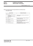
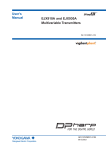
2.
Handling Cautions
When the transmitter is delivered, visually check them
to make sure that no damage occurred during shipment.
Also check that all transmitter mounting hardware shown
in Figure 2.1 is included. If the transmitter was ordered
without the mounting bracket or without the process
connector, the transmitter mounting hardware is not
included.
Table 2.1
Applicable Model Code for Mounting
Hardware
B
EJ110
1
D
EJ120
2
G
EJ130
- -
3
J
EJ310
4
K
EJ430
M
EJ440
1
2
EJX910A
-
3
EJX930A
4
B
D
G
- J
K
M
Applicable
Suffix code
model
EJ110
EJ120 Process
EJ130 connections
1,2,3 and 4
EJX910A
EJX930A
Part name
Qty
Process connector bolt
Process connector
4
2
Process connector
gasket
2
EJ210
EJ310
EJ430
EJ440
Process connector bolt
Process connector
Process connector
gasket
2
1
1
EJ510
EJ530
F
- -
EJX610A
L
EJX630A
U-bolt
1
EJ118
B
- -
EJ438
J
U-bolt nut
2
Mounting bracket
(L or flat type)
1
Transmitter mounting
bolt
4
Mounting bracket
B,D,G,J,K and
M*
EJ110
Mounting
bracket M (For
measurement
span code other
than F)
EJX910A
EJX930A
Mounting bracket
F and L
Mounting bracket
Option code /TF1
Cable gland and RTD cable
(EJX910A and EJX930A only)
Bolt
Process connector
Process connector
Gasket
U-bolt
1
2
EJ118
F0201.ai
1 ea.
2 ea.
External
temperature input
Cable gland
1, 2, 3 and 4
Teflon film
Fluorinated oil
Teflon film
Fluorinated oil
2
B
D
EJ115 - -
J
K
2
1
Option code /TF1
1
2
EJ210 - -
3
4
1
2
1
External
temperature input
RTD cable
B, C and D
EJ210
EJ438
*:
U-bolt
U-bolt nut
Mounting bracket
Transmitter mounting
bolt
U-bolt (L and S)
U-bolt nut (L and S)
1
2
3
4
B
C
D
Handling Cautions
Process
connections
1,2,3 and 4
EJ110
EJ120
EJ130
EJ310
EJ430
EJ440
EJ118
EJ438
EJ115
EJX910A
EJX930A
EJ510
EJ530
EJX610A
EJX630A
5
<2. Handling Cautions>
1
1
2
2
Mounting bracket
(Flat type)
Mounting bracket
(L type)
U-bolt nut
Transmitter mounting bolt
U-bolt nut (L)
Teflon film
Fluorinated oil
For measurement span code F.
Mounting bracket
U-bolt nut (S)
U-bolt (S)
U-bolt (L)
Figure 2.1
Transmitter Mounting Hardware
F0202.ai
IM 01C25A01-01E
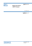
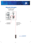
2.1 Model and Specifications
Check
The model name and specifications are indicated on the
name plate attached to the case.
F0203.ai
Figure 2.2 6
<2. Handling Cautions>
Name Plate
2.2 Selecting the Installation
Location
The transmitter is designed to withstand severe
environmental conditions. However, to ensure that it will
provide years of stable and accurate performance, take
the following precautions when selecting the installation
location.
(a) Ambient Temperature
Avoid locations subject to wide temperature variations
or a significant temperature gradient. If the location is
exposed to radiant heat from plant equipment, provide
adequate thermal insulation and/or ventilation.
(b) Ambient Atmosphere
Do not install the transmitter in a corrosive
atmosphere. If this cannot be avoided, there must be
adequate ventilation as well as measures to prevent
the leaking of rain water and the presence of standing
water in the conduits.
(c) Shock and Vibration
Although the transmitter is designed to be relatively
resistant to shock and vibration, an installation site
should be selected where this is kept to a minimum.
(d) Installation of Explosion-protected Transmitters
An explosion-protected transmitters is certified for
installation in a hazardous area containing specific
gas types. See subsection 2.4 “Installation of an
Explosion-Protected Instrument.”
2.3 Pressure Connection
WARNING
• Never loosen the process connector bolts when an
instrument is installed in a process. The device is
under pressure, and a loss of seal can result in a
sudden and uncontrolled release of process fluid.
• When draining toxic process fluids that have
condensed inside the pressure detector, take
appropriate steps to prevent the contact of such
fluids with the skin or eyes and the inhalation of
vapors from these fluids.
The following precautions must be observed in order to
safely operate the transmitter under pressure.
(a) Make sure that the process connector bolts are
tightened firmly.
(b) Make sure that there are no leaks in the impulse
piping.
(c) Never apply a pressure higher than the specified
maximum working pressure.
2.4 Installation of an ExplosionProtected Instrument
If a customer makes a repair or modification to an
intrinsically safe or explosionproof instrument and the
instrument is not restored to its original condition, its
intrinsically safe or explosionproof construction may be
compromised and the instrument may be hazardous to
operate. Please contact Yokogawa before making any
repair or modification to an instrument.
CAUTION
This instrument has been tested and certified as
being intrinsically safe or explosionproof. Please
note that severe restrictions apply to this instrument’s
construction, installation, external wiring, maintenance
and repair. A failure to abide by these restrictions could
make the instrument a hazard to operate.
WARNING
Maintaining the safety of explosionproof equipment
requires great care during mounting, wiring, and
piping. Safety requirements also place restrictions on
maintenance and repair. Please read the following
sections very carefully.
IM 01C25A01-01E
WARNING
The range setting switch must not be used in a
hazardous area.
IMPORTANT
For combined approval types
Once a device of multiple approval type is installed,
it should not be re-installed using any other approval
types. Apply a permanent mark in the check box of
the selected approval type on the certification label on
the transmitter to distinguish it from unused approval
types.
2.4.1 FM Approval
Caution for FM intrinsically safe type. (Following
contents refer “DOC. No. IFM022-A12”)
Note 1. EJX/EJA-E Series pressure transmitters with
optional code /FS1 are applicable for use in
hazardous locations.
• Applicable Standard: FM3600, FM3610, FM3611,
FM3810
• Intrinsically Safe for Class I, Division 1, Groups A,
B, C & D. Class II, Division 1, Groups E, F & G and
Class III, Division 1, Class I, Zone 0 in Hazardous
Locations, AEx ia IIC
• Nonincendive for Class I, Division 2, Groups
A, B, C & D. Class II, Division 2, Groups F & G
and Class I, Zone 2, Groups IIC, in Hazardous
Locations.
• Enclosure: Type 4X
• Temperature Class: T4
• Ambient temperature: –60 to 60°C
Note 2. Entity Parameters
• Intrinsically Safe Apparatus Parameters
[Groups A, B, C, D, E, F and G]
Vmax = 30 V
Ci = 6 nF
Imax = 200 mA
Li = 0 µH
Pmax = 1 W
* Associated Apparatus Parameters
(FM approved barriers)
Voc ≤ 30 V
Ca > 6 nF
Isc ≤ 200 mA
La > 0 µH
Pmax ≤ 1W
• Intrinsically Safe Apparatus Parameters
[Groups C, D, E, F and G]
Vmax = 30 V
Ci = 6 nF
Imax = 225 mA
Li = 0 µH
Pmax = 1 W
* Associated Apparatus Parameters
(FM approved barriers)
Voc ≤ 30 V
Ca > 6 nF
Isc ≤ 225 mA
La > 0 µH
Pmax ≤ 1 W
•
Entity Installation Requirements
Vmax ≥ Voc or Uo or Vt, Imax ≥ Isc or Io or It,
Pmax (or Po) ≤ Pi, Ca or Co ≥ Ci + Ccable,
La or Lo ≥ Li + Lcable
Note 3. Installation
• Barrier must be installed in an enclosure that
meets the requirements of ANSI/ISA S82.01.
• Control equipment connected to barrier must not
use or generate more than 250 V rms or V dc.
• Installation should be in accordance with ANSI/ISA
RP12.6 “Installation of Intrinsically Safe Systems
for Hazardous (Classified) Locations” and the
National Electric Code (ANSI/NFPA 70).
• The configuration of associated apparatus must be
FMRC Approved.
• Dust-tight conduit seal must be used when
installed in a Class II, III, Group E, F and G
environments.
• Associated apparatus manufacturer’s installation
drawing must be followed when installing this
apparatus.
• The maximum power delivered from the barrier
must not exceed 1 W.
• Note a warning label worded “SUBSTITUTION
OF COMPONENTS MAY IMPAIR INTRINSIC
SAFETY,” and “INSTALL IN ACCORDANCE WITH
DOC. No. IFM022-A12”
Note 4. Maintenance and Repair
• The instrument modification or parts replacement
by other than authorized representative of
Yokogawa Electric Corporation is prohibited and
will void Factory Mutual Intrinsically safe and
Nonincendive Approval.
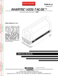
[Intrinsically Safe]
Hazardous Location
Class I, II, III, Division 1,
Groups A, B, C, D, E, F, G
Class 1, Zone 0 in
Hazardous (Classified)
Locations AEx ia IIC
Pressure Transmitters
+
Supply
–
Nonhazardous Location
Safety Barrier
+
+
–
–
General
Purpose
Equipment
+
–
F0204.ai
IM 01C25A01-01E
2
Handling Cautions
a. FM Intrinsically Safe for HART/BRAIN
Protocol Type (Except for EJX90A)
7
<2. Handling Cautions>
IFM024-A12
[Nonincendive]
Hazardous Location
Nonhazardous Location
Class I, II, Division 2,
Groups A, B, C, D, F, G
Class 1, Zone 2, Group IIC,
in Hazardous (Classified)
Locations
+
–
General
Purpose
Equipment
Pressure Transmitters
Supply
8
<2. Handling Cautions>
Installation Diagram for Intrinsically Safe
(Division 1 Installation)
Terminator
+
−
+
Not Use
Safety Barrier
–
Pressure
Transmitter
+
− Field Instruments
F0205.ai
b. FM Intrinsically Safe for Fieldbus Type
(Except for EJX90A)
EJX/EJA-E Series pressure transmitters with optional
code /FS15 are applicable for use in hazardous
locations.
• Applicable standard:
FM3600, FM3610, FM3611, FM3810,
ANSI/NEMA250, IEC60079-27
• FM Intrinsically Safe Approval
[Entity Model]
Class I, II & III, Division 1, Groups A, B, C, D, E, F
& G, Temperature Class T4 Ta=60°C, Type 4X and
Class I, Zone 0, AEx ia IIC, Temperature Class T4
Ta=60°C, Type 4X
[FISCO Model]
Class I, II & III, Division 1, Groups A, B, C, D, E, F
& G, Temperature Class T4 Ta=60°C, Type 4X and
Class I, Zone 0, AEx ia IIC, Temperature Class T4
Ta=60°C, Type 4X
• Nonincendive Approval
Class I, Division 2, Groups A, B, C & D Temperature Class T4 Ta=60°C, Type 4X and
Class II, Division 2, Groups F & G Temperature
Class T4 Ta=60°C, Type 4X and Class I, Zone 2,
Group IIC, Temperature Class T4 Ta=60°C, Type
4X
• Electrical Connection: 1/2 NPT female, M20
female
• Caution for FM Intrinsically safe type. (Following
contents refer to “DOC. No. IFM024-A12 p.1, p.2,
p.3, p.4-1 and p.4-2.”)
+
− Field Instruments
Hazardous Location
Terminator
Non-Hazardous Location
−
+
Safety Barrier
+
−
F0223.ai
Note 1. Barrier must be installed in an enclosure that
meets the requirements of ANSI/ISA 61010-1.
Note 2. Control equipment connected to the Associ
ated Apparatus must not use or generate more
than 250 Vrms or Vdc.
Note 3. Installation should be in accordance with ANSI/
ISA 12.06.01 “Installation of Intrinsi cally Safe
Systems for Hazardous (Classified) Locations”
and the National Electrical Code (ANSI/NFPA
70) Sections 504 and 505.
Note 4. The configuration of Associated Apparatus must
be Factory Mutual Research Approved under
FISCO Concept.
Note 5. Associated Apparatus manufacturer’s installa
tion drawing must be followed when installing
this equipment.
Note 6. No revision to drawing without prior Factory
Mutual Research Approval.
Note 7. Terminator must be FM Approved.
Note 8. Note a warning label worded “SUBSTITU TION
OF COMPONENTS MAY IMPAIR INTRINSIC
SAFETY”, and “INSTALL IN ACCORDANCE
DOC.NO.IFM024-A12 P.1 TO 4.”
IM 01C25A01-01E
Electrical Data:
Note: In the rating 1, the output current of the barrier must be
limited by a resistor “Ra” such that Io=Uo/Ra. In the rating
2 or 3, the output characteristics of the barrier must be the
type of trapezoid which are certified as the FISCO model
(See “FISCO Rules”). The safety barrier may include
a terminator. More than one field instruments may be
connected to the power supply line.
FISCO Rules
The FISCO Concept allows the interconnection of
intrinsincally safe apparatus to associated apparatus
not specifically examined in such combination. The
criterion for such interconnection is that the voltage (Ui),
the current (Ii) and the power (Pi) which intrinsically
safe apparatus can receive and remain intrinsically
safe, considering faults, must be equal or greater than
the voltage (Uo, Voc, Vt), the current (Io, Isc, It) and the
power (Po) which can be provided by the associated
apparatus (supply unit).
Po ≤ Pi, Uo ≤ Ui, Io ≤ Ii
In addition, the maximum unprotected residual
capacitance (Ci) and inductance (Li) of each apparatus
(other than the terminators) connected to the fieldbus
must be less than or equal to 5 nF and 10 µH
respectively.
Ci ≤ 5nF, Li ≤ 10µH
In each I.S. fieldbus segment only one active source,
normally the associated apparatus, is allowed to provide
the necessary power for the fieldbus system. The
allowed voltage (Uo, Voc,Vt) of the associated apparatus
used to supply the bus cable must be limited to the range
of 14 V dc to 17.5 V dc. All other equipment connected
to the bus cable has to be passive, meaning that the
apparatus is not allowed to provide energy to the system,
except to a leakage current of 50 µA for each connected
device.
Supply unit
Trapezoidal or rectangular output characteristic only
Uo = 14...17.5 V (I.S. maximum value)
Io according to spark test result or other assessment.
No specification of Lo and Co is required on the
certificate or label.
Cable
The cable used to interconnect the devices needs to
comply with the following parameters:
Loop resistance R’: 15...150 Ω/km
Inductance per unit length L’: 0.4...1 mH/km
Capacitance per unit length C’: 45...200 nF/km.
C’=C’ line/line + 0.5 C’ line/screen, if both lines are
floating or C’=C’ line/line + C’ line/screen, if the screen
is connected to one line.
Length of spur cable: max. 60 m
Length of trunk cable: max. 1 km (Group IIC) or 5 km
(Group IIB)
Length of splice: max.1 m
Terminators
At each end of the trunk cable an FM approved line
terminator with the following parameters is suitable:
R = 90...100 Ω
C = 0...2.2 mF
System evaluations
The number of passive device like transmitters, actuators,
hand held terminals connected to a single bus segment is
not limited due to I.S. reasons. Furthermore, if the above
rules are respected, the inductance and capacitance of
the cable need not to be considered and will not impair
the intrinsic safety of the installation.
HAZARDOUS AREA
SAFE AREA
Supply Unit and
Safety Barrier
(FISCO Model)
Terminator
(FISCO Model)
Ex i
U
U
I
HandheldTerminal
Field Instruments
(Passive)
Terminator
Data
F0224.ai
I.S. fieldbus system complying with FISCO model
IM 01C25A01-01E
2
Handling Cautions
• Rating 1 (Entity)
For Groups A, B, C, D, E, F, and G or Group IIC
Maximum Input Voltage Vmax: 24 V
Maximum Input Current Imax: 250 mA
Maximum Input Power Pmax: 1.2 W
Maximum Internal Capacitance Ci: 3.52 nF
Maximum Internal Inductance Li: 0 µH
or
• Rating 2 (FISCO)
For Groups A, B, C, D, E, F, and G or Group IIC
Maximum Input Voltage Vmax: 17.5 V
Maximum Input Current Imax: 380 mA
Maximum Input Power Pmax: 5.32 W
Maximum Internal Capacitance Ci: 3.52 nF
Maximum Internal Inductance Li: 0 µH
or
• Rating 3 (FISCO)
For Groups C, D, E, F, and G or Group IIB
Maximum Input Voltage Vmax: 17.5 V
Maximum Input Current Imax: 460 mA
Maximum Input Power Pmax: 5.32 W
Maximum Internal Capacitance Ci: 3.52 nF
Maximum Internal Inductance Li: 0 µH
9
<2. Handling Cautions>
Installation Diagram for Nonincendive
(Division 2 Installation)
Terminator
+
−
+
−
+
−
SUPPLY
Pressure
Transmitter
Transmitter
Note 11. If ordinary location wiring methods are used,
the transmitter shall be connected to FM
Approved associated non-incendive field wiring
apparatus.
Electrical data:
Vmax: 32V
Ci: 3.52 nF
Li: 0 µH
Transmitter
Hazardous location
Non-Hazardous location
Terminator
+
−
General Purpose
Equipment
+
−
10
<2. Handling Cautions>
FM Approved
Associated Nonincendive Field
Wiring Apparatus
Vt or Voc
It or Isc
Ca
La
F0225.ai
Note 1. Installation should be in accordance with the
National Electrical Code ® (ANSI/NFPA 70)
Article 500.
Note 2. The configuration of Associated Nonincendive
Field Wiring Apparatus must be FM Approved.
Note 3. Approved under FNICO Concept.
Note 4. Dust-tight conduit seal must be used when
installed in Class II and Class III environments.
Note 5. Associated Apparatus manufacturer’s
installation drawing must be followed when
installing this apparatus.
Note 6. No revision to drawing without prior FM
Approvals.
Note 7. Terminator must be FM Approved.
Note 8. The nonincendive field wiring circuit concept
allows interconection of nonincendive field
wiring apparatus with associated nonincendive
field wiring apparatus, using any of the wiring
methods permitted for unclassified locations.
Note 9. Installation requirements;
Vmax ≥ Voc or Vt
Imax = see note 10.
Ca ≥ Ci + Ccable
La ≥ Li + Lcable
Note 10. For this current controlled circuit, the parameter
(Imax 3 ) is not required and need not be
aligned with parameter (Isc 3 ) of the barrier or
associated nonincendive field wiring apparatus.
FNICO Rules
The FNICO Concept allows the interconnection of
nonincendive field wiring apparatus to associated
nonincendive field wiring apparatus not specifically
examined in such combination. The criterion for such
interconnection is that the voltage (Vmax), the current
(Imax) and the power (Pmax) which nonincendive field
wiring apparatus can receive and remain nonincendive,
considering faults, must be equal or greater than the
voltage (Uo, Voc or Vt), the current (Io, Isc or It) and the
power (Po) which can be provided by the associated
nonincendive field wiring apparatus (supply unit). In
addition the maximum unprotected residual capacitance
(Ci) and inductance (Li) of each apparatus (other than
terminators) connected to the Fieldbus must be less than
or equal to 5nF and 10uH respectively.
In each N.I. Fieldbus segment only one active source,
normally the associated nonincendive field wiring
apparatus, is allowed to provide the necessary power for
the Fieldbus system. The allowed voltage (Uo, Voc or
Vt) of the associated nonincendive field wiring apparatus
used to supply the bus cable must be limited to the range
14Vdc to 17.5Vdc. All other equipment connected to the
bus cable has to be passive, meaning that the apparatus
is not allowed to provide energy to the system, except
a leakage current of 50É A for each connected device.
Separately powered equipment needs galvanic isolation
to ensure the nonincendive field wiring Fieldbus circuit
remains passive.
Cable
The cable used to interconnect the devices needs to
comply with the following parameters:
Loop resistance R’: 15...150 Ω/km
Inductance per unit length L’: 0.4...1 mH/km
Capacitance per unit length C’: 80....200 nF/km
C’ =C’ line/line+0.5 C’ line/screen, if both lines
are floating or C’ = C’ line/line + C’ line/screen, if
thescreen is connected to one line.
Length of spur cable: max. 30 m
Length of trunk cable: max. 1 km
Length of splice: max = 1 m
Terminators
At the end of each trunk cable an FM Approved line
terminator with the following parameters is suitable:
R= 90...100 Ω
C = 0 ....2.2 uF
IM 01C25A01-01E
c. FM Intrinsically Safe for Fieldbus Type for
EJX90A
IFM026-A12
Installation Diagram for Intrinsically Safe
(Division 1 Installation)
Terminator
+
–
Pressure
Transmitter
+
– Field Instruments
+
– Field Instruments
Hazardous Location
Terminator
–
+
Safety Barrier
+
–
Non-Hazardous Location
Note 2. Control equipment connected to the Associ ated
Apparatus must not use or generate more than
250 Vrms or Vdc.
Note 3. Installation should be in accordance with ANSI/
ISA 12.06.01 “Installation of Intrinsi cally Safe
Systems for Hazardous (Classified) Locations”
and the National Electrical Code (ANSI/NFPA
70) Sections 504 and 505.
Note 4. The configuration of Associated Apparatus must
be Factory Mutual Research Approved under
FISCO Concept.
Note 5. Associated Apparatus manufacturer’s installa
tion drawing must be followed when installing
this equipment.
Note 6. No revision to drawing without prior Factory
Mutual Research Approval.
Note 7. Terminator must be FM Approved.
Note 8. Note a warning label worded “SUBSTITU TION
OF COMPONENTS MAY IMPAIR INTRINSIC
SAFETY”, and “INSTALL IN ACCORDANCE
DOC.NO.IFM026-A12 P.1 TO 4.”
Electrical Data:
• Rating 1 (Entity)
For Groups A, B, C, D, F, and G or Group IIC
Maximum Input Voltage Vmax: 24 V
Maximum Input Current Imax: 250 mA
Maximum Input Power Pmax: 1.2 W
Maximum Internal Capacitance Ci: 3.52 nF
Maximum Internal Inductance Li: 0 μH
or
• Rating 2 (FISCO)
For Groups A, B, C, D, F, and G or Group IIC
Maximum Input Voltage Vmax: 17.5 V
Maximum Input Current Imax: 380 mA
Maximum Input Power Pmax: 5.32 W
Maximum Internal Capacitance Ci: 3.52 nF
Maximum Internal Inductance Li: 0 μH
or
• Rating 3 (FISCO)
For Groups C, D, F, and G or Group IIB
Maximum Input Voltage Vmax: 17.5 V
Maximum Input Current Imax: 460 mA
Maximum Input Power Pmax: 5.32 W
Maximum Internal Capacitance Ci: 3.52 nF
Maximum Internal Inductance Li: 0 μH
Sensor Circuit: Uo=6.51 V, Io=4 mA,
Po=6 mW, Co=34 µF, Lo=500 mH
F0226.ai
Note 1. Barrier must be installed in an enclosure that
meets the requirements of ANSI/ISA 61010-1.
Note: In the rating 1, the output current of the barrier must be
limited by a resistor “Ra” such that Io=Uo/Ra. In the rating
2 or 3, the output characteristics of the barrier must be the
type of trapezoid which are certified as the FISCO model
(See “FISCO Rules”). The safety barrier may include
a terminator. More than one field instruments may be
connected to the power supply line.
IM 01C25A01-01E
2
Handling Cautions
EJX multivariable transmitter with optional code
/FS15 are applicable for use in hazardous locations.
• Applicable standard: FM3600, FM3610, FM3611,
FM3810, ANSI/NEMA250, IEC60079-27
• FM Intrinsically Safe Approval
[Entity Model]
Class I, II & III, Division 1, Groups A, B, C, D, F &
G, Temperature Class T4 Ta=60ºC, Type 4X and
Class I, Zone 0, AEx ia IIC, Temperature Class T4
Ta=60ºC, Type 4X
[FISCO Model]
Class I, II & III, Division 1, Groups A, B, C, D, F &
G, Temperature Class T4 Ta=60ºC, Type 4X and
Class I, Zone 0, AEx ia IIC, Temperature Class T4
Ta=60ºC, Type 4X
• Nonincendive Approval
Class I, Division 2, Groups A, B, C & D Temperature Class T4 Ta=60ºC, Type 4X and
Class II, Division 2, Groups F & G Temperature
Class T4 Ta=60ºC, Type 4X and Class I, Zone 2,
Group IIC, Temperature Class T4 Ta=60ºC, Type
4X and Class III, Division 1, Temperature Class T4
Ta=60ºC, Type 4X
• Electrical Connection: 1/2 NPT female, M20
female
• Caution for FM Intrinsically safe type. (Following
contents refer to “DOC. No. IFM026-A12 p.1 to
p.4.”)
11
<2. Handling Cautions>
●
FISCO Rules
12
<2. Handling Cautions>
System evaluations
The FISCO Concept allows the interconnection of
intrinsincally safe apparatus to associated apparatus
not specifically examined in such combination. The
criterion for such interconnection is that the voltage (Ui),
the current (Ii) and the power (Pi) which intrinsically
safe apparatus can receive and remain intrinsically
safe, considering faults, must be equal or greater than
the voltage (Uo, Voc, Vt), the current (Io, Isc, It) and the
power (Po) which can be provided by the associated
apparatus (supply unit).
The number of passive device like transmitters,
actuators, hand held terminals connected to a single
bus segment is not limited due to I.S. reasons. Furthermore, if the above rules are respected, the
inductance and capacitance of the cable need not to
be considered and will not impair the intrinsic safety of
the installation.
HAZARDOUS AREA
SAFE AREA
Supply Unit and
Safety Barrier
(FISCO Model)
Terminator
(FISCO Model)
Po ≤ Pi, Uo ≤ Ui, Io ≤ Ii
Ex i
U
In addition, the maximum unprotected residual
capacitance (Ci) and inductance (Li) of each apparatus
(other than the terminators) connected to the fieldbus
must be less than or equal to 5 nF and 10 µH
respectively.
U
I
HandheldTerminal
Terminator
Data
Ci ≤ 5nF, Li ≤ 10µH
In each I.S. fieldbus segment only one active source,
normally the associated apparatus, is allowed to provide
the necessary power for the fieldbus system. The allowed
voltage(Uo, Voc,Vt) of the associated apparatus used to
supply the bus cable must be limited to the range of 14 V
dc to 17.5 V dc. All other equipment connected to the bus
cable has to be passive, meaning that the apparatus is
not allowed to provide energy to the system, except to a
leakage current of 50 µA for each connected device.
Field Instruments
(Passive)
●
Installation Diagram for Nonincendive
(Division 2 Installation)
Terminator
Supply unit
Trapezoidal or rectangular output characteristic only
Uo = 14...17.5 V (I.S. maximum value)
Io according to spark test result or other assessment.
No specification of Lo and Co is required on the
certificate or label.
Cable
The cable used to interconnect the devices needs to
comply with the following parameters:
Loop resistance R’: 15...150 Ω/km
Inductance per unit length L’: 0.4...1 mH/km
Capacitance per unit length C’: 45...200 nF/km.
C’=C’ line/line + 0.5 C’ line/screen, if both lines are
floating or C’=C’ line/line + C’ line/screen, if the screen
is connected to one line.
Length of spur cable: max. 60 m
Length of trunk cable: max. 1 km (Group IIC) or 5 km
(Group IIB)
Length of splice: max.1m
Terminators
At each end of the trunk cable an FM approved line
terminator with the following parameters is suitable:
R = 90...100 Ω
C = 0...2.2 mF
F0227.ai
I.S. fieldbus system complying with FISCO model
+
–
SUPPLY
Pressure
Transmitter
+
–
Transmitter
+
–
Transmitter
Hazardous Location
Non-Hazardous Location
Terminator
+
–
+
–
General Purpose
Equipment
FM Approved
Associated Nonincendive Field
Wiring Apparatus
Vt or Voc
It or Isc
Ca
La
F0228.ai
Note 1. Installation should be in accordance with the
National Electrical Code ® (ANSI/NFPA 70)
Article 500.
Note 2. The configuration of Associated Nonincendive
Field Wiring Apparatus must be FM Approved.
Note 3. Approved under FNICO Concept.
IM 01C25A01-01E
Note 4. Dust-tight conduit seal must be used when
installed in Class II and Class III environments.
Note 5. Associated Apparatus manufacturer’s
installation drawing must be followed when
installing this apparatus.
Note 6. No revision to drawing without prior FM
Approvals.
Note 7. Terminator must be FM Approved.
Note 8. The nonincendive field wiring circuit concept
allows interconection of nonincendive field
wiring apparatus with associated nonincendive
field wiring apparatus, using any of the wiring
methods permitted for unclassified locations.
Note 9. Installation requirements;
Vmax ≥ Voc or Vt
Imax = see note 10.
Ca ≥ Ci + Ccable
La ≥ Li + Lcable
Note 11. If ordinary location wiring methods are used, the
transmitter shall be connected to FM Approved
associated nonincendive field wiring apparatus.
Electrical data:
Vmax: 32V
Ci: 3.52 nF
Li: 0 µH
●
FNICO Rules
The FNICO Concept allows the interconnection of
nonincendive field wiring apparatus to associated
nonincendive field wiring apparatus not specifically
examined in such combination. The criterion for such
interconnection is that the voltage (Vmax), the current
(Imax) and the power (Pmax) which nonincendive field
wiring apparatus can receive and remain nonincendive,
considering faults, must be equal or greater than the
voltage (Uo, Voc or Vt), the current (Io, Isc or It) and the
power (Po) which can be provided by the associated
nonincendive field wiring apparatus (supply unit). In
addition the maximum unprotected residual capacitance
(Ci) and inductance (Li) of each apparatus (other than
terminators) connected to the Fieldbus must be less than
or equal to 5nF and 20uH respectively.
In each N.I. Fieldbus segment only one active source,
normally the associated nonincendive field wiring
apparatus, is allowed to provide the necessary power for
the Fieldbus system. The allowed voltage (Uo, Voc or
Vt) of the associated nonincendive field wiring apparatus
used to supply the bus cable must be limited to the range
14Vdc to 17.5Vdc. All other equipment connected to the
bus cable has to be passive, meaning that the apparatus
is not allowed to provide energy to the system, except
a leakage current of 50 µA for each connected device.
Separately powered equipment needs galvanic isolation
to ensure the nonincendive field wiring Fieldbus circuit
remains passive.
Cable
The cable used to interconnect the devices needs to
comply with the following parameters:
Loop resistance R’: 15...150 Ω/km
Inductance per unit length L’: 0.4...1 mH/km
Capacitance per unit length C’: 45....200 nF/km
C’ =C’ line/line+0.5 C’ line/screen, if both lines are
floating or C’ = C’ line/line + C’ line/screen, if the
screen is connected to one line.
Length of spur cable: max. 60 m
Length of trunk cable: max. 1 km (Group IIC) or
5 km (Group IIB)
Length of splice: max = 1 m
Terminators
At the end of each trunk cable an FM Approved line
terminator with the following parameters is suitable:
R= 90...100 Ω
C = 0 ....2.2 mF
d. FM Explosionproof
Caution for FM explosionproof type.
Note 1. EJX/EJA-E Series pressure transmitters with
optional code /FF1 or /V1F are applicable for
use in hazardous locations.
• Applicable Standard: FM3600, FM3615, FM3810,
ANSI/NEMA 250 • Explosionproof for Class I, Division 1, Groups B, C
and D.
• Dust-ignitionproof for Class II/III, Division 1,
Groups E, F and G.
• Enclosure: Type 4X
• Temperature Class: T6
• Ambient Temperature: –40 to 60°C
• Supply Voltage: 42 V dc max.
32 V dc max. (FOUNDATION Fieldbus and
PROFIBUS PA type)
9 to 28 V dc, 27 mW (Low Power type)
9 to 30 V dc, 250 mW (RS485 Modbus
Communication Type)
• Output signal: 4 to 20 mA
15 mA (FOUNDATION Fieldbus and PROFIBUS PA
type)
1 to 5 V (Low Power type)
RS485 Modbus (RS485 Modbus Communication
Type)
IM 01C25A01-01E
2
Handling Cautions
Note 10. For this current controlled circuit, the parameter
(Imax) is not required and need not be aligned
with parameter (Isc) of the barrier or associated
nonincendive field wiring apparatus.
13
<2. Handling Cautions>
14
<2. Handling Cautions>
Note 2. Wiring
• All wiring shall comply with National Electrical
Code ANSI/NFPA70 and Local Electrical Codes.
• When installed in Division 1, “FACTORY SEALED,
CONDUIT SEAL NOT REQUIRED.”
• Wiring connection for output signal code Q (Low
Power type) shall follow the diagram below.
Pressure Transmitters
SUPPLY +
A
Voltmeter
Power Supply
+
+
–
–
SUPPLY –
Three-Wire Connection
Pressure Transmitters
SUPPLY +
A
Voltmeter
Power Supply
+
+
–
–
SUPPLY –
Four-Wire Connection
F0218.ai
Note 3. Operation
• Keep the “WARNING” nameplate attached to the
transmitter.
WARNING: OPEN CIRCUIT BEFORE
REMOVING COVER. FACTORY SEALED,
CONDUIT SEAL NOT REQUIRED. INSTALL IN
ACCORDANCE WITH THE USERS MANUAL IM
01C25.
• Take care not to generate mechanical sparking
when accessing to the instrument and peripheral
devices in a hazardous location.
Note 4. Maintenance and Repair
• The instrument modification or parts replacement
by other than authorized representative of
Yokogawa Electric Corporation is prohibited and
will void Factory Mutual Explosionproof Approval.
e. FM Intrinsically Safe and Explosion Proof
Combination for HART/BRAIN Protocol
Type
EJX/EJA-E Series pressure transmitters with
optional code /FU1 or /V1U1 can be selected the
type of protection (FM Intrinsically Safe or FM
Explosionproof) for use in hazardous locations.
Note 1. For the installation of this transmitter, once a
particular type of protection is selected, any
other type of protection cannot be used. The
installation must be in accordance with the
description about the type of protection in this
instruction manual.
Note 2. In order to avoid confusion, unnecessary
marking is crossed out on the label other
than the selected type of protection when the
transmitter is installed.
2.4.2 CSA Certification
a. CSA Intrinsically Safe for HART/BRAIN
Protocol Type (Except for EJX90A)
Caution for CSA Intrinsically safe and nonincendive
type. (Following contents refer to “DOC No. ICS013A13”)
Note 1. EJX/EJA-E Series pressure transmitters with
optional code /CS1 are applicable for use in
hazardous locations.
Certificate: 1606623
[For CSA C22.2]
• Applicable Standard: C22.2 No.0, C22.2 No.0.4,
C22.2 No.25, C22.2 No.94, C22.2 No.157,
C22.2 No.213, C22.2 No.60079-0,
C22.2 No.61010-1 , C22.2 No.61010-2-030
• Intrinsically Safe for Class I, Division 1, Groups
A, B, C & D, Class II, Division 1, Groups E, F & G,
Class III, Division 1
• Nonincendive for Class I, Division 2, Groups A, B,
C & D, Class II, Division 2, Groups F & G, Class III,
Division 1
• Enclosure: Type 4X
• Temp. Code: T4
• Amb. Temp.: –50* to 60°C
* –15°C when /HE is specified.
• Process Temperature: 120°C max.
[For CSA E60079]
• Applicable Standard: CAN/CSA E60079-11,
CAN/CSA E60079-15, IEC 60529:2001
• Ex ia IIC T4, Ex nL IIC T4 • Ambient Temperature: –50 to 60°C
• Max. Process Temp.: 120°C
• Enclosure: IP66/IP67
Note 2. Entity Parameters
• Intrinsically safe ratings are as follows:
Maximum Input Voltage (Vmax/Ui) = 30 V
Maximum Input Current (Imax/Ii) = 200 mA
Maximum Input Power (Pmax/Pi) = 0.9 W
Maximum Internal Capacitance (Ci) = 10 nF
Maximum Internal Inductance (Li) = 0 µH
• Type "n" or Nonincendive ratings are as follows:
Maximum Input Voltage (Vmax/Ui) = 30 V
Maximum Internal Capacitance (Ci) = 10 nF
Maximum Internal Inductance (Li) = 0 µH
• Installation Requirements
Uo ≤ Ui, Io ≤ Ii, Po ≤ Pi,
Co ≥ Ci + Ccable, Lo ≥ Li + Lcable
Voc ≤ Vmax, Isc ≤ Imax,
Ca ≥ Ci + Ccable, La ≥ Li + Lcable
Uo, Io, Po, Co, Lo, Voc, Isc, Ca and La are
parameters of barrier.
IM 01C25A01-01E
Note 3. Installation
• In any safety barreir used output current must
be limited by a resistor 'R' such that Io=Uo/R or
Isc=Voc/R.
• The safety barrier must be CSA certified.
• Input voltage of the safety barrier must be less
than 250 Vrms/Vdc.
• Installation should be in accordance with Canadian
Electrical Code Part I and Local Electrical Code.
• Dust-tight conduit seal must be used when
installed in Class II and III environments.
• The instrument modification or parts replacement
by other than authorized representative of
Yokogawa Electric Corporation and Yokogawa
Corporation of America is prohibited and will
void Canadian Standards Intrinsically safe and
nonincendive Certification.
[Intrinsically Safe]
Hazardous Location
Nonhazardous Location
Pressure Transmitters
+
–
Safety Barrier
• CSA Intrinsically Safe Approval
Class I, Division 1, Groups A, B, C, & D; Class II,
Division 1, Groups E, F & G; Class III; Ex ia IIC T4
Ambient Temperature: –40* to 60°C (–40* to
140°F) Encl. Type 4X, IP66/IP67
* –15°C when /HE is specified.
• CSA Nonincendive Approval
Class I, Division 2, Groups A, B, C, & D; Class II,
Division 2, Groups F & G; Class III; Ex nL IIC T4
Ambient Temperature: –40* to 60°C (–40* to
140°F) Encl. Type 4X, IP66/ IP67
* –15°C when /HE is specified.
Caution for CSA Intrinsically Safe Type.
(Following Contents Refer to “DOC. No.
ICS018)
Installation Diagram for Intrinsically Safe
(Division 1 Installation)
Terminator
+
–
General
Purpose
Equipment
+
+
+
–
–
–
+
– Field Instruments
[Nonincendive]
Hazardous Location
Nonhazardous Location
Hazardous Location
Group IIC, Zone 2
CSA Certified
Equipment
([nL] or
nonincendive)
Pressure Transmitters
+
Supply
–
+
Not Use
Safety Barrier
Pressure
Transmitter
+
– Field Instruments
F0206.ai
Class I, II, Division 2,
Groups A, B, C, D, F, G
Class III, Division 1.
2
–
F0207.ai
b. CSA Intrinsically Safe for Fieldbus Type
(Except for EJX90A)
EJX/EJA-E Series pressure transmitters with optional
code /CS15 are applicable for use in hazardous
locations.
• Certificate: 1689689
• Applicable standard: C22.2 No.0, C22.2 No.0.4,
C22.2 No.25, C22.2 No.94, C22.2 No.157,
C22.2 No.213, C22.2 No.61010-1,
C22.2 No.61010-2-030, C22.2 No.60079-0,
CAN/CSA E60079-0, CAN/CSA E60079-11,
CAN/CSA E60079-15, IEC 60529
Terminator
–
+
Safety Barrier
+
–
Non-Hazardous Location
F0229.ai
Note 1. The safety barrier must be CSA certified.
Note 2. Input voltage of the safety barrier must be less
than 250Vrms/Vdc.
Note 3. Installation should be in accordance with
Canadian Electrical Code Part I and local
Electrical Code.
Note 4. Do not alter drawing without authorization from
CSA.
Electrical Data:
• Rating 1 (Entity)
For Groups A, B, C, D, E, F, and G or Group IIC
Ui (vmax) = 24 V dc
Ii (Imax) = 250 mA
Pi (Pmax) = 1.2 W
Ci = 3.52 nF
Li = 0 μH
or
IM 01C25A01-01E
Handling Cautions
Group IIC, Zone 0
Class I, II, III, Division 1,
Groups A, B, C, D, E, F, G
Supply
15
<2. Handling Cautions>
• Rating 2 (FISCO)
For Groups A, B, C, D, E, F, and G or Group IIC
Ui (vmax) = 17.5 V dc
Ii (Imax) = 380 mA
Pi (Pmax) = 5.32 W
Ci = 3.52 nF
Li = 0 μH
or
• Rating 3 (FISCO)
For Groups C, D, E, F, and G or Group IIB
Ui (vmax) = 17.5 V dc
Ii (Imax) = 460 mA
Pi (Pmax) = 5.32 W
Ci = 3.52 nF
Li = 0 μH
Installation requirements;
Po ≤ Pi Uo ≤ Ui Io ≤ Ii,
Co ≥ Ci + Ccable Lo ≥ Li + Lcable
Vmax ≥ Voc Imax ≥ Isc
Ca ≥ Ci + Ccable La ≥ Li + Lcable
Uo, Io, Po, Co, Lo,Voc, Isc, Ca and La are parameters
of barrier.
Caution for CSA Non-incendive Type.
(Following contents refer to “DOC. No.
ICS018)
Installation Diagram for Non-incendive or Type of
protection “n” (Division 2 Installation)
Terminator
+
–
SUPPLY
Pressure
Transmitter
+
–
Transmitter
+
–
Transmitter
Non-Hazardous location
Terminator
–
CSA Certified
Equipment [nL]
+
Note 2. Dust-tight conduit seal must be used when
installed in class II and III environments.
Note 3. Do not alter drawing without authorization from
CSA.
Electrical Data:
• Rating (including FNICO)
Ui or Vmax = 32 V
Ci = 3.52 nF
Li = 0 μH
c. CSA Explosionproof Type
Caution for CSA explosionproof type.
Note 1. EJX/EJA-E Series pressure transmitters with
optional code /CF1 or /V1F are applicable for
use in hazardous locations.
• Certificate: 2014354
• Applicable Standard: C22.2 No.0,
C22.2 No.0.4, C22.2 No.0.5, C22.2 No.25,
C22.2 No.30, C22.2 No.94, C22.2 No.61010-1,
C22.2 No.61010-2-030, C22.2 No.60079-0,
C22.2 No.60079-1
• Explosion-proof for Class I, Groups B, C and D.
• Dustignition-proof for Class II/III, Groups E, F and
G.
• Enclosure: Type 4X
• Temperature Code: T6...T4
• Ex d IIC T6...T4 • Enclosure: IP66/IP67
• Maximum Process Temperature: 120°C (T4),
100°C (T5), 85°C (T6)
• Ambient Temperature: –50* to 75°C (T4),
–50* to 80°C (T5), –50* to 75°C (T6)
Hazardous location
+
16
<2. Handling Cautions>
–
F0230.ai
Note 1. Installation should be in accordance with
Canadian Electrical Code Part I and local
Electrical Code.
* –15°C when /HE is specified.
• Supply Voltage: 42 V dc max.
32 V dc max. (FOUNDATION Fieldbus and
PROFIBUS PA type)
9 to 28 V dc, 27 mW (Low Power type)
9 to 30 V dc, 250 mW (RS485 Modbus
Communication Type)
• Output Signal: 4 to 20 mA dc
15 mA (FOUNDATION Fieldbus and PROFIBUS PA
type)
1 to 5 V (Low Power type)
RS485 Modbus (RS485 Modbus Communication
Type)
Note 2. Wiring
• All wiring shall comply with Canadian Electrical
Code Part I and Local Electrical Codes.
• In hazardous location, wiring shall be in conduit as
shown in the figure.
• WARNING:
A SEAL SHALL BE INSTALLED WITHIN 50cm OF
THE ENCLOSURE.
UN SCELLEMENT DOIT ÊTRE INSTALLÉ À
MOINS DE 50cm DU BOÎTIER.
IM 01C25A01-01E
17
<2. Handling Cautions>
• WARNING: WHEN INSTALLED IN CL.I, DIV 2, SEAL NOT
REQUIRED.
UNE FOIS INSTALLÉ DANS CL I, DIV 2, AUCUN
JOINT N'EST REQUIS.
Non-Hazardous Hazardous Locations Division 1
Locations
Non-hazardous
50 cm Max.
Location Equipment
42 V DC Max.
4 to 20 mA DC
Signal
Sealing Fitting
Conduit
Transmitter
F0208.ai
Non-Hazardous Hazardous Locations Division 2
Locations
Sealing Fitting
Transmitter
F0209.ai
• All wiring shall comply with local installation
requirements and local electrical code.
• In hazardous locations, the cable entry devices
shall be of a certified flameproof type, suitable for
the conditions of use and correctly installed.
• Unused apertures shall be closed with suitable
flameproof certified blanking elements. (The plug
attached is flameproof certified.)
• Wiring connection for output signal code Q (Low
Power type) shall follow the diagram below.
Pressure Transmitters
SUPPLY +
A
Voltmeter
Power Supply
+
+
–
–
Pressure Transmitters
Note 2. In order to avoid confusion, unnecessary
marking is crossed out on the label other
than the selected type of protection when the
transmitter is installed.
a. ATEX Intrinsically Safe for HART/BRAIN
Protocol Type (Except for EJX90A)
Voltmeter
Power Supply
+
+
–
–
SUPPLY –
Four-Wire Connection
Note 1. For the installation of this transmitter, once a
particular type of protection is selected, any
other type of protection cannot be used. The
installation must be in accordance with the
description about the type of protection in this
instruction manual.
(1) Technical Data
Three-Wire Connection
A
EJX/EJA-E Series pressure transmitters with
optional code /CU1 or /V1U1 can be selected the
type of protection (CSA Intrinsically Safe or CSA
Explosionproof) for use in hazardous locations.
2.4.3 ATEX Certification
SUPPLY –
SUPPLY +
d. CSA Intrinsically Safe and Explosion-proof
Combination for HART/BRAIN Protocol
Type (Except for EJX90A)
F0219.ai
Caution for ATEX Intrinsically safe type.
Note 1. EJX/EJA-E Series pressure transmitters with
optional code /KS21 for potentially explosive
atmospheres.
• No. DEKRA 11ATEX0228 X
• Applicable Standard:
EN 60079-0:2009, EN 60079-11:2007,
EN 60079-26:2007, EN 61241-11:2006
IM 01C25A01-01E
2
Handling Cautions
Note 4. Maintenance and Repair
• The instrument modification or parts replacement
by other than authorized representative of
Yokogawa Electric Corporation and Yokogawa
Corporation of America is prohibited and will void
Canadian Standards Explosionproof Certification.
Non-hazardous
Location Equipment
42 V DC Max.
4 to 20 mA DC
Signal
Note 3. Operation
• WARNING:
AFTER DE-ENERGIZING, DELAY 5 MINUTES
BEFORE OPENING.
APRÉS POWER-OFF, ATTENDRE 5 MINUTES
AVANT D'OUVRIR.
• WARNING: WHEN AMBIENT TEMPERATURE ≥ 65°C, USE
THE HEAT-RESISTING CABLES ≥ 90°C.
QUAND LA TEMPÉRATURE AMBIANTE ≥ 65°C,
UTILISEZ DES CÂBLES RÉSISTANTES Á LA
CHALEUR ≥ 90°C.
• Take care not to generate mechanical sparking
when accessing to the instrument and peripheral
devices in a hazardous location.
• Type of Protection and Marking code:
Ex ia IIC T4 Ga
Ex ia IIIC T85 ºC T100 ºC T120 ºC Db
• Group: II
• Category: 1G, 2D
• Ambient Temperature for EPL Ga:
–50 to 60°C
• Ambient Temperature for EPL Db:
–30* to 60°C
WARNING
* –15°C when /HE is specified.
• Process Temperature (Tp.): 120°C max.
• Maximum Surface Temperature for EPL Db:
T85°C (Tp.: 80°C)
T100°C (Tp.: 100°C)
T120°C (Tp.: 120°C)
• Enclosure: IP66 / IP67
Note 2 Electrical Data
• In type of explosion protection intrinsic safety Ex ia
IIC or Ex ia IIIC, only for connection to a certified
intrinsically safe circuit with following maximum
values:
Ui = 30 V
Ii = 200 mA
Pi = 0.9 W
(Linear Source)
Maximum internal capacitance; Ci = 27.6 nF
Maximum internal inductance; Li = 0 µH
Note 3. Installation
• Refer to the control drawing. All wiring shall comply
with local installation requirements.
[Control Drawing]
Hazardous Location
Nonhazardous Location
Pressure Transmitters
Supply
+
+
–
–
Safety Barrier *1
F0210.ai
18
<2. Handling Cautions>
*1: In any safety barriers used the output current must be
limited by a resistor “R” such that Io=Uz/R.
Note 4. Maintenance and Repair
• The instrument modification or parts replacement
by other than authorized representative of
Yokogawa Electric Corporation is prohibited and
will void DEKRA Intrinsically safe Certification.
Note 5. Special Conditions for Safe Use
• In the case where the enclosure of the Pressure
Transmitter is made of aluminium, if it is mounted
in an area where the use of category 1 G
apparatus is required, it must be installed such,
that, even in the event of rare incidents, ignition
sources due to impact and friction sparks are
excluded.
• Electrostatic charge may cause an exlosion
hazard. Avoid any actions that cause the
generation of electrostatic charge, such as rubbing
with a dry cloth on coating face of the product.
• In case of the enclosure of the Pressure
Transmitter with paint layers, if it is mounted in an
area where the use of category 2D apparatus is
required, it shall be installed in such a way that the
risk from electrostatic discharges and propagating
brush discharges caused by rapid flow of dust is
avoided.
• To satisfy IP66 or IP67, apply waterproof glands to
the electrical connection port.
• When the lightning protector option is specified,
the apparatus is not capable of withstanding the
500V insulation test required by EN60079-11. This
must be taken into account when installing the
apparatus.
b. ATEX Intrinsically Safe for HART Protocol
Type for EJX90A
Caution for ATEX Intrinsically safe type.
Note 1. EJX multivariable transmitter with optional
code /KS2 are applicable for use in hazardous
locations.
• No. KEMA 06ATEX 0037X
• Applicable Standard:
EN 50014:1997, EN 50020:2002,
EN 50284:1999, EN 50281-1-1:1998
• Type of Protection and Marking code:
EEx ia IIC T4
• Group: II
• Category: 1G, 1D
• Ambient Temperature for gas-proof:
–50* to 60°C
* –15°C when /HE is specified.
* –15°C when /HE is specified.
• Process Temperature (Tp.): 120°C max.
• Maximum Surface Temperature for dust-proof:
T85°C (Tamb.: –40* to 60°C, Tp.: 80°C)
T100°C (Tamb.: –40* to 60°C, Tp.: 100°C)
T120°C (Tamb.: –40* to 60°C, Tp.: 120°C)
• Enclosure: IP66 and IP67
IM 01C25A01-01E
Note 3. Installation
• All wiring shall comply with local installation
requirements. (Refer to the installation diagram)
• When the analog and pulse circuits are connected
to separate barriers, it shall be assured that the
voltage difference between these output circuits is
not more than 30 V.
• When used in a potentially explosive atmosphere,
Requiring the use of apparatus of equipment
category 1D or 2D, certified cable entry devices
shall be used that are suitable for the application
and correctly installed.
Note 4. Maintenance and Repair
• The instrument modification or parts replacement
by other than authorized representative of
Yokogawa Electric Corporation is prohibited and
will void KEMA Intrinsically safe Certification.
[Installation Diagram] (for EJX910A and EJX930A)
● Without pulse output
Hazardous Location
Nonhazardous Location
Pressure Transmitters
+
Supply
–
Sensor out
+
–
Safety Barrier*1
RTD sensor
*2
● With pulse output
Hazardous Location
Pressure Transmitters
+
Supply
–
Pulse
+
Sensor out
RTD sensor
*2
Nonhazardous Location
+
–
+
–
Safety Barrier*1
2
Safety Barrier*1
F0211.ai
*1: • In any safety barriers used the output current must be
limited by a resistor “R” such that Io=Uz/R.
• The safety barrier shall be certified by notify body EU as
ATEX.
• When using non isolation barrier, connect to IS earthing
system.
*2: • RTD sensor is prepared by the user.
• The sensor signal line must withstand a test voltage of
500 V AC.
WARNING
To satisfy IP66 or IP67, apply waterproof glands to the
electrical connection port.
Note 5. Special Conditions for Safe Use
• In the case where the enclosure of the Pressure
Transmitter is made of aluminium, if it is mounted
in an area where the use of category 1 G
apparatus is required, it must be installed such,
that, even in the event of rare incidents, ignition
sources due to impact and friction sparks are
excluded.
IM 01C25A01-01E
Handling Cautions
Note 2. Electrical Data
[Supply/Output circuit (terminals + and -)]
In type of explosion protection intrinsic safety EEx
ia IIC, only for connection to a certified intrinsically
safe circuit with following maximum values:
Ui = 30 V
Ii = 200 mA
Pi = 0.9 W
Effective internal capacitance; Ci = 10 nF
Effective internal inductance; Li = 0 mH
[Pulse Output circuit (terminals - and pulse)]
In type of explosion protection intrinsic safety EEx
ia IIC, only for connection to a certified intrinsically
safe circuit with following maximum values:
Ui = 30 V
Ii = 200 mA
Pi = 0.9 W
Ci = 10 nF
Li = 0 mH
[External temperature input circuit (connector)]
In type of explosion protection intrinsic safety EEx
ia IIC, with following maximum values:
Uo = 30 V
Io = 95.4 mA
Po= 468 mW
Co = 11 nF
Lo= 3.9 mH
19
<2. Handling Cautions>
c. ATEX Intrinsically Safe for Fieldbus Type
(Except for EJX90A)
Caution for ATEX Intrinsically safe type.
Note 1. EJX/EJA-E series pressure transmitters with
optional code /KS26 are applicable for use in
hazardous locations.
• No. KEMA 04ATEX1116 X
• Applicable Standard: EN 60079-0:2009,
EN 60079-11:2007/EN 60079-11:2012,
EN 60079-26:2007, EN 60079-27:2008,
EN 61241-11:2006
Note 2. Ratings
Type of Protection and Marking Code:
Ex ia IIC/IIB T4 Ga
Ex ia IIIC T85°C T100°C T120°C Db
Group: II
Category: 1G, 2D
Ambient Temperature for EPL Ga: –40 to 60°C
Ambient Temperature for EPL Db: –30* to 60°C
* –15°C when /HE is specified.
Maximum Process Temperature (Tp.): 120°C
Maximum Surface Temperature for EPL Db.
T85°C (Tp.: 80°C)
T100°C (Tp.: 100°C)
T120°C (Tp.: 120°C)
Ambient Humidity:
0 to 100% (No condensation)
Degree of Protection of the Enclosure:
IP66 / IP67
Electrical Data
• When combined with Trapezoidal and Rectangular
output characteristic FISCO model IIC barrier
Ui = 17.5 V, Ii = 380 mA, Pi = 5.32 W,
Ci = 3.52 nF, Li = 0 μH
• When combined with Linear characteristic barrier
Ui = 24 V, Ii = 250 mA, Pi = 1.2 W,
Ci = 3.52 nF, Li = 0 μH
• When combined with Trapezoidal or Rectangular
output characteristic FISCO model IIB barrier
Ui = 17.5 V, Ii = 460 mA, Pi = 5.32 W,
Ci = 3.52 nF, Li = 0 μH
WARNING
• In the case where the enclosure of the Pressure
Transmitter is made of aluminium, if it is mounted
in an area where the use of category 1 G
apparatus is required, it must be installed such,
that even in the event of rare incidents, ignition
sources due to impact and friction sparks are
excluded.
• Electrostatic charge may cause an explosion
hazard. Avoid any actions that cause the
generation of electrostatic charge, such as rubbing
with a dry cloth on coating face of the product.
• In the case where the enclosure of the Pressure
Transmitter is made of aluminum, if it is mounted in
an area where the use of category 2D apparatus is
required, it shall be installed in such a way that the
risk from electrostatic discharges and propagating
brush discharges caused by rapid flow of dust is
avoided.
• To satisfy IP66 or IP67, apply waterproof glands to
the electrical connection port.
• When the lightning protector option is specified,
the apparatus is not capable of withstanding the
500V insulation test required by EN60079-11.
This must be taken into account when installing
the apparatus.
Note 6. Installation Instructions
[Installation Diagram]
Terminator
+
Pressure
− SUPPLY Transmitter
Note 3. Installation
• All wiring shall comply with local installation
requirements. (Refer to the installation diagram)
Note 4. Maintenance and Repair
• The instrument modification or parts replacement
by other than authorized representative of
Yokogawa Electric Corporation is prohibited and
will void DEKRA Intrinsically safe Certification.
20
<2. Handling Cautions>
+
−
Transmitter
+
−
Transmitter
Hazardous Location
Terminator
−
+
Safety Barrier
+
−
Non-Hazardous Location
F0231.ai
Note 5. Special Conditions for Safe Use
IM 01C25A01-01E
d. ATEX Intrinsically Safe for Fieldbus Type
for EJX90A
Caution for ATEX Intrinsically safe type.
Note 1. EJX multivariable transmitter with optional
code /KS26 are applicable for use in hazardous
locations:
• No. KEMA 06ATEX0278 X
• Applicable Standard: EN 60079-0:2009,
EN 60079-11:2012, EN 60079-26:2007
Note 2. Ratings
Type of Protection and Marking Code:
Ex ia IIC/IIB T4 Ga
Ex ia IIIC T85°C T100°C T120°C Db
Group: II
Category: 1G, 2D
21
Ambient Temperature for EPL Ga:
–40 to 60°C
Ambient Temperature for EPL Db:
–30* to 60°C
* –15°C when /HE is specified.
Maximum Process Temperature (Tp.): 120°C
Maximum Surface Temperature for EPL Db.
T85°C (Tp.: 80°C)
T100°C (Tp.: 100°C)
T120°C (Tp.: 120°C)
Ambient Humidity:
0 to 100% (No condensation)
Degree of Protection of the Enclosure:
IP66/IP67
Electrical Data
• When combined with Trapezoidal or Rectanglar
output characteristic FISCO model IIC barrier
[Supply circuit (terminals + and -)]
Ui = 17.5 V, Ii = 380 mA, Pi = 5.32 W,
Ci = 3.52 nF, Li = 0 µH
[Sensor circuit]
Uo = 7.63 V, Io = 3.85 mA, Po = 0.008 W,
Co = 4.8 µF, Lo = 100 mH
• When combined with Linear characteristic barrier
[Supply circuit (terminals + and -)]
Ui = 24 V, Ii = 250 mA, Pi = 1.2 W,
Ci = 3.52 nF, Li = 0 µH
[Sensor circuit]
Uo = 7.63 V, Io = 3.85 mA, Po = 0.008 W,
Co = 4.8 µF, Lo = 100 mH
• When combined with Trapezoidal or Rectanglar
output characteristic FISCO model IIB barrier
[Supply circuit (terminals + and -)]
Ui = 17.5 V, Ii = 460 mA, Pi = 5.32 W,
Ci = 3.52 nF, Li = 0 µH
[Sensor circuit]
Uo = 7.63 V, Io = 3.85 mA, Po = 0.008 W,
Co = 4.8 µF, Lo = 100 mH
Note 3. Installation
• All wiring shall comply with local installation
requirements. (Refer to the installation diagram)
Note 4. Maintenance and Repair
• The instrument modification or parts replacement
by other than authorized representative of
Yokogawa Electric Corporation is prohibited and
will void DEKRA Intrinsically safe Certification.
Note 5. Special Conditions for Safe Use
IM 01C25A01-01E
2
Handling Cautions
• In the rating 1(*1), the output current of the barrier
must be limited by a resistor ‘Ra’ such that Io = Uo/
Ra.
• In the rating 2(*2), the output of the barrier must be
the characteristics of the trapezoid or the rectangle
and this transmitter can be connected to Fieldbus
equipment which are in according to the FISCO
model.
• The terminators may be built in by a barrier.
• More than one transmitter may be connected to
the power supply line.
• The terminator and the safety barrier shall be
certified.
Electrical data:
Maximum Input Voltage Ui: 24 V
Maximum Input Current Ii: 250 mA
*1:
Maximum Input Power Pi: 1.2 W
Rating 1
Maximum Internal Capacitance Ci: 3.52 nF
Maximum Internal Inductance Li: 0 μH
or
Maximum Input Voltage Ui: 17.5 V
Maximum Input Current Ii: 380 mA
Maximum Input Power Pi: 5.32 W
Maximum Internal Capacitance Ci: 3.52 nF
Maximum Internal Inductance Li: 0 μH
*2:
or
Rating 2
Maximum Input Voltage Ui: 17.5 V
Maximum Input Current Ii: 460 mA
Maximum Input Power Pi: 5.32 W
Maximum Internal Capacitance Ci: 3.52 nF
Maximum Internal Inductance Li: 0 μH
<2. Handling Cautions>
<2. Handling Cautions>
WARNING
• In the case where the enclosure of the Pressure
Transmitter is made of aluminium, if it is mounted
in an area where the use of category 1G apparatus
is required, it must be installed such, that even in
the event of rare incidents, ignition sources due to
impact and friction sparks are excluded.
• Electrostatic charge may cause an explosion
hazard. Avoid any actions that cause the
generation of electrostatic charge, such as rubbing
with a dry cloth on coating face of the product.
• In the case where the enclosure of the Pressure
Transmitter is made of aluminum, if it is mounted in
an area where the use of category 2D apparatus is
required, it shall be installed in such a way that the
risk from electrostatic discharges and propagating
brush discharges caused by rapid flow of dust is
avoided.
• To satisfy IP66 or IP67, apply waterproof glands to
the electrical connection port.
• When the lightning protector option is specified,
the apparatus is not capable of withstanding the
500V insulation test required by EN60079-11.
This must be taken into account when installing
the apparatus.
Note 6. Installation instructions
[Installation Diagram]
Terminator
RTD
Pt100.3wire
+
Pressure
− SUPPLY Transmitter
+
−
+
−
−
+
Safety Barrier
+
−
• The terminators may be built in by a barrier.
• More than one transmitter may be connected to
the power supply line.
• The terminator and the safety barrier shall be
certified.
Electrical data:
Supply circuit
Maximum Input Voltage Ui: 24 V
Maximum Input Current Ii: 250 mA
*1:
Maximum Input Power Pi: 1.2 W
Rating 1
Maximum Internal Capacitance Ci: 3.52 nF
Maximum Internal Inductance Li: 0 μH
or
Maximum Input Voltage Ui: 17.5 V
Maximum Input Current Ii: 380 mA
Maximum Input Power Pi: 5.32 W
Maximum Internal Capacitance Ci: 3.52 nF
Maximum Internal Inductance Li: 0 μH
*2:
or
Rating 2
Maximum Input Voltage Ui: 17.5 V
Maximum Input Current Ii: 460 mA
Maximum Input Power Pi: 5.32 W
Maximum Internal Capacitance Ci: 3.52 nF
Maximum Internal Inductance Li: 0 μH
Sensor circuit
Maximum Output Voltage Uo: 7.63 V
Maximum Output Current Io: 3.85 mA
Maximum Output Power Po: 0.008 W
Maximum Internal Capacitance Co: 4.8 μF
Maximum Internal Inductance Lo: 100 mH
• RTD sensor is prepared by the user.
The sensor signal line must suited a test voltage of
500Vac.
e. ATEX Flameproof Type
Caution for ATEX flameproof type.
Transmitter
Transmitter
Hazardous Location
Terminator
22
Non-Hazardous Location
F0232.ai
• In the rating 1(*1), the output current of the barrier
must be limited by a resistor ‘Ra’ such that Io = Uo/
Ra.
• In the rating 2(*2), the output of the barrier must be
the characteristics of the trapezoid or the rectangle
and this transmitter can be connected to Fieldbus
equipment which are in according to the FISCO
model.
Note 1. EJX/EJA-E Series pressure transmitters with
optional code /KF22 or /V1F are applicable for
use in hazardous locations.
• No. KEMA 07ATEX0109 X
• Applicable Standard: EN 60079-0:2009,
EN 60079-1:2007, EN 60079-31:2009
• Type of Protection and Marking Code:
Ex d IIC T6...T4 Gb, Ex tb IIIC T85°C Db
• Group: II
• Category: 2G, 2D
• Enclosure: IP66 / IP67
• Temperature Class for gas-poof:
T6, T5, and T4
• Ambient Temperature for gas-proof:
–50 to 75°C (T6), –50 to 80°C (T5), and
–50 to 75°C (T4)
• Maximum Process Temperature (Tp.) for gasproof:
85°C (T6), 100°C (T5), and 120°C (T4)
IM 01C25A01-01E
23
<2. Handling Cautions>
• Maximum Surface Temperature for dust-proof:
T85°C (Tamb.: –30* to 75°C, Tp.: 85°C)
WARNING
* –15°C when /HE is specified.
Note 2. Electrical Data
• Supply voltage: 42 V dc max.
32 V dc max. (FOUNDATION Fieldbus and
PROFIBUS PA type)
9 to 28 V dc, 27 mW (Low Power type)
9 to 30 V dc, 250 mW (RS485 Modbus
Communication Type)
• Output signal: 4 to 20 mA
15 mA (FOUNDATION Fieldbus and PROFIBUS PA
type)
1 to 5 V (Low Power type)
RS485 Modbus (RS485 Modbus Communication
Type)
Pressure Transmitters
SUPPLY +
A
Voltmeter
Power Supply
+
+
–
–
SUPPLY –
Three-Wire Connection
Pressure Transmitters
SUPPLY +
A
Voltmeter
Power Supply
+
+
–
–
ATEX Intrinsically Safe and ATEX
Flameproof Combination for HART/BRAIN
Protocol Type (Except for EJX90A)
EJX/EJA-E Series pressure transmitters with optional
code /KU22 or /V1U1 can be selected the type of
protection ATEX Flameproof, Intrinsically Safe. Ex ia,
or Ex ic for use in hazardous area.
Note 1. For the installation of this transmitter, once a
particular type of protection is selected, any
other type of protection cannot be used. The
installation must be in accordance with the
description about the type of protection in this
user’s manual.
Note 2. For combined approval types
Once a device of multiple approval type is
installed, it should not be re-installed using any
other approval types. Apply a permanent mark
in the check box of the selected approval type
on the certification label on the transmitter to
distinguish it from unused approval types.
ATEX Intrinsically Safe Ex ic
SUPPLY –
Four-Wire Connection
f.
F0220.ai
Note 4. Operation
• Keep the “WARNING” label attached to the
transmitter.
WARNING: AFTER DE-ENERGIZING, DELAY
5 MINUTES BEFORE OPENING. WHEN THE
AMBIENT TEMP.≥65°C, USE HEAT-RESISTING
CABLE AND CABLE GLAND ≥90°C.
• Take care not to generate mechanical sparking
when accessing to the instrument and peripheral
devices in a hazardous location.
Note 5. Special Conditions for Safe Use
Caution for ATEX intrinsically safe Ex ic
• Applicable Standard:
EN 60079-0:2009/EN 60079-0:2012,
EN 60079-11:2012
• Type of Protection and Marking Code:
II 3G Ex ic IIC T4 Gc
• Ambient Temperature: –30* to +60°C
* –15°C when /HE is specified.
• Ambient Humidity:
0 to 100% (No condensation)
• Maximum Process Temperature: 120°C
• IP Code: IP66
• Ambient pollution degree: 2
• Overvoltage category: I
IM 01C25A01-01E
2
Handling Cautions
Note 3. Installation
• All wiring shall comply with local installation
requirement.
• Cable glands, adapters and/or blanking elements
with a suitable IP rating shall be of Ex d IIC/Ex tb
IIIC certified by ATEX and shall be installed so as
to maintain the specific degree of protection (IP
Code) of the equipment.
• Wiring connection for output signal code Q (Low
Power type) shall follow the diagram below.
• Electrostatic charge may cause an explosion
hazard. Avoid any actions that cause the
generation of electrostatic charge, such as rubbing
with a dry cloth on coating face of the product.
• In the case where the enclosure of the Pressure
Transmitter is made of aluminium, if it is mounted
in an area where the use of category 2D apparatus
is required, it shall be installed in such a way
that the risk from electrostatic discharges and
propagating brush discharges caused by rapid
flow of dust is avoided.
• The instrument modification or parts replacement
by other than an authorized Representative of
Yokogawa Electric Corporation is prohibited and
will void the certification.
24
<2. Handling Cautions>
Note 1. Electrical Data
Ui = 30 V
Ci = 27.6 nF
Li = 0 µH
Note 2. Installation
• All wiring shall comply with local installation
requirements. (refer to the control drawing)
• Cable glands, adapters and/or blanking elements
shall be of Ex “n”, Ex “e” or Ex “d” and shall be
installed so as to maintain the specified degree of
protection (IP Code) of the transmitters.
Note 3. Maintenance and Repair
• The instrument modification or parts replacement
by other than authorized representative of
Yokogawa Electric Corporation is prohibited and
will void ATEX intrinsically safe.
[Control Drawing]
Hazardous Area
Nonhazardous Area
+
Pressure
Transmitters
–
Associated
Apparatus
F0212.ai
Note 4. Specific Conditions of Use
WARNING
• Electrostatic charge may cause an explosion
hazard. Avoid any actions that cause the
generation of electrostatic charge, such as rubbing
with a dry cloth on coating face of the product.
• When the lightning protector option is specified,
the apparatus is not capable of withstanding the
500V insulation test required by EN60079-11. This
must be taken into account when installing the
apparatus.
• Maximum Process Temperature: 120°C
• Ambient Humidity:
0 to 100% (No condensation)
• IP Code: IP66
• Ambient pollution degree: 2
• Overvoltage category: I
Note 1. Electrical Data
Ui = 32 V
Ci = 3.52 nF
Li = 0 µH
Note 2. Installation
• All wiring shall comply with local installation
requirements. (refer to the control drawing)
• When installing the transmitter in “ic” FISCO
system or FNICO system, follow the installation
requirements of each system.
• Cable glands, adapters and/or blanking elements
shall be of Ex “n”, Ex “e” or Ex “d” and shall be
installed so as to maintain the specified degree of
protection (IP Code) of the transmitters.
Note 3. Maintenance and Repair
• The instrument modification or parts replacement
by other than authorized representative of
Yokogawa Electric Corporation is prohibited and
will void ATEX intrinsically safe.
[Control Drawing]
Hazardous Area
Transmitter
Nonhazardous Area
+
–
Associated
Apparatus
F0233.ai
• Above drawing shows the installation of Entity
system.
When installing the transmitters in “ic” FISCO
system or FNICO system, follow the installation
requirements of each system.
Note 4. Specific Conditions of Use
g. ATEX Intrinsically Safe Ex ic for Fieldbus
Type (Except for EJX90A)
Caution for ATEX Intrinsically safe Ex ic.
EJX/EJA-E Series pressure transmitters with optional
code /KN26 are applicable for use in hazardous
locations.
• Applicable Standard:
EN 60079-0:2009/EN 60079-0:2012,
EN 60079-11:2012
• Type of Protection and Marking Code:
II 3G Ex ic IIC T4 Gc
• Ambient Temperature: –30* to +60°C
WARNING
• Electrostatic charge may cause an explosion
hazard. Avoid any actions that cause the
gerenation of eletrostatic charge, such as rubbing
with a dry cloth on coating face of the product.
• When the lightning protector option is specified,
the apparatus is not capable of withstanding the
500V insulation test required by EN60079-11. This
must be taken into account when installing the
apparatus.
* –15°C when /HE is specified.
IM 01C25A01-01E
25
<2. Handling Cautions>
(2) Electrical Connection
(6) Name Plate
A mark indicating the electrical connection type is
stamped near the electrical connection port. These
marks are as followed.
Screw Size
ISO M20 × 1.5 female
ANSI 1/2 NPT female
Name plate
Marking
M
N or
Tag plate for flameproof type
W
No. KEMA 07ATEX0109 X
Ex d IIC T6...T4 Gb, Ex tb IIIC T85°C Db
Enlcosure : IP66/IP67
TEMP. CLASS
T6 T5
T4
MAX PROCESS TEMP.(Tp.)
85 100 120 °C
Tamb.
-50 to 75
80
75 °C
T85°C(Tamb.:-30(-15) to 75°C, Tp.:85°C)(for Dust)
D
*3
WARNING
Location of the mark
F0214.ai
AFTER DE-ENERGIZING, DELAY 5 MINUTES BEFORE
OPENING.
WHEN THE AMBIENT TEMP. ≥ 65°C, USE THE
HEAT-RESISTING CABLE & CABLE GLAND ≥ 90°C
POTENTIAL ELECTROSTATIC CHARGING HAZARD
(3) Installation
WARNING
[Except for EJX90A]
Tag plate for intrinsically safe Ex ia for HART/BRAIN
No. DEKRA 11ATEX 0228 X
Ex ia IIC T4 Ga Ta: -50 TO 60°C
Ex ia IIIC T85°C T100°C T120°C Db Ta:-30(-15) TO 60°C
IP66/IP67
MAX. PROCESS TEMP.(Tp.) 120°C
T85°C(Tp.:80°C), T100°C(Tp.:100°C), T120°C(Tp.:120°C)
Ui=30V, Ii=200mA , Pi=0.9W, Ci=27.6nF, Li=0µH
D
*3
WARNING
POTENTIAL ELECTROSTATIC
CHARGING HAZARD
- SEE USER’S MANUAL
(4) Operation
Tag plate for intrinsically safe Ex ic for HART/BRAIN
Ex ic IIC T4 Gc
IP66
Tamb -30(-15) TO 60°C
MAX. PROCESS TEMP. 120°C
Ui=30V, Ci=27.6nF, Li=0µH
WARNING
• OPEN CIRCUIT BEFORE REMOVING COVER.
INSTALL IN ACCORDANCE WITH THIS USER’S
MANUAL
• Take care not to generate mechanical sparking
when access to the instrument and peripheral
devices in a hazardous location.
WARNING
POTENTIAL ELECTROSTATIC
CHARGING HAZARD
- SEE USER’S MANUAL
Tag plate for intrinsically safe Ex ia for Fieldbus
No. KEMA 04ATEX1116 X
Ex ia IIC/IIB T4 Ga Ta:-40 to 60°C
Ex ia IIIC T85°C T100°C T120°C Db Ta:-30(-15) to 60°C
MAX PROCESS TEMP.(Tp.):120°C
T85°C(Tp.:80°C), T100°C(Tp.:100°C), T120°C(Tp.:120°C)
Enclosure: IP66/IP67
FISCO field device(IIC/IIB)
Entity parameters Ui=24V, Ii=250mA, Pi=1.2W, Ci=3.52nF, Li=0μH
(5) Maintenance and Repair
WARNING
The instrument modification or parts replacement by
other than an authorized Representative of Yokogawa
Electric Corporation is prohibited and will void the
certification.
D
*3
WARNING
POTENTIAL ELECTROSTATIC CHARGING HAZARD - SEE USER'S MANUAL.
Tag plate for intrinsically safe Ex ic for Fieldbus
Ex ic IIC T4 Gc
IP66
Tamb -30(-15) TO 60°C
MAX. PROCESS TEMP. 120°C
Ui=32V, Ci=3.52nF, Li=0µH
WARNING
POTENTIAL ELECTROSTATIC CHARGING HAZARD - SEE USER'S MANUAL.
F0215-2.ai
IM 01C25A01-01E
2
Handling Cautions
• All wiring shall comply with local installation
requirements and the local electrical code.
• There is no need for conduit seal in Division 1
and Division 2 hazardous locations because this
product is sealed at the factory.
F0215-1.ai
26
<2. Handling Cautions>
[EJX90A]
Tag plate for intrinsically safe for HART/BRAIN
No. KEMA 06ATEX0037 X
EEx ia IIC T4
IP66 and IP67
Tamb. -50(-15) to 60°C MIN Tamb.for DUST -40(-15°C)
MAX PROCESS TEMP.(Tp) 120°C
T85°C(Tp.:80°C), T100°C(Tp.:100°C), T120°C(Tp.:120°C)
Supply/Pulse circuit
Ui=30 V, Ii=200 mA, Pi=0.9 W, Ci=10 nF, Li=0 mH
Sensor circuit
Uo=30 V, Io=95.4 mA, Po=468 mW, Co=11 nF, Lo=3.9 mH
*3
Note 1. For the installation of this transmitter, once a
particular type of protection is selected, any
other type of protection cannot be used. The
installation must be in accordance with the
description about the type of protection in this
instruction manual.
Note 2. For combined approval types, once a device of
multiple approval type is installed, it should not
be re-installed using any other approval types.
Apply a permanent mark in the check box of the
selected approval type on the certification label
on the transmitter to distinguish it from unused
approval types.
D
Tag plate for intrinsically safe Ex ia for Fieldbus
No. KEMA 06ATEX0278 X
Ex ia IIC/IIB T4 Ga Ta: -40 to 60°C
Ex ia IIIC T85°C T100°C T120°C Db Ta: -30(-15) to 60°C
MAX PROCESS TEMP.(Tp.): 120°C
T85°C (Tp.: 80°C), T100°C (Tp.: 100°C), T120°C (Tp.: 120°C)
ENCLOSURE: IP66/IP67
Supply circuit
FISCO field device(IIC/IIB)
Entity Parameter Ui=24V, Ii=250mA, Pi=1.2W, Ci=3.52nF, Li=0µH
Sensor circuit
Uo=7.63V, Io=3.85mA, Po=0.008W, Co=4.8uF, Lo=100mH
a. IECEx Intrinsically Safe Ex ia for HART/
BRAIN Protocol Type (Except for EJX90A)
*3
Caution for IECEx Intrinsically safe Ex ia.
POTENTIAL ELECTROSTATIC CHARGING HAZARD-SEE USER'S MANUAL.
F0215-3.ai
MODEL: Specified model code.
STYLE: Style code.
SUFFIX: Specified suffix code.
SUPPLY: Supply voltage.
OUTPUT: Output signal.
MWP: Maximum working pressure.
CAL RNG: Specified calibration range.
NO.: Serial number and year of production*1.
TOKYO 180-8750 JAPAN:
The manufacturer name and the address*2.
Note 2. Electrical Data
Maximum Input Voltage (Ui) = 30 V
Maximum Input Current (Ii) = 200 mA
Maximum Input Power (Pi) = 0.9 W (linear source)
Maximum Internal Capacitance (Ci) = 27.6 nF
Maximum Internal Inductance (Li) = 0 μH
*1:The first number in the second block of “NO.” column
is the last one number of the production year. second block
NO. 91K819857
132
7
The year 2011
*2: “180-8750” is a zip code which represents the following address.
2-9-32 Nakacho, Musashino-shi, Tokyo Japan Note 1. EJX/EJA-E series pressure transmitters with
optional code /SU21 are applicable for use in
hazardous locations
• No. IECEx DEK 11.0081X
• Applicable Standard: IEC 60079-0:2011,
IEC 60079-11:2011, IEC 60079-26:2006
• Ex ia IIC T4 Ga
• Ambient Temperature: –50 to 60°C
• Max. Process Temp.: 120°C *3:The identification number of Notified Body.
2.4.4 IECEx Certification
Model EJX Series pressure transmitters with optional
code /SU21 can be selected the type of protection
(IECEx Intrinsically Safe Ex ia, Ex ic or flameproof) for
use in hazardous locations.
EJX Series pressure transmitters with optional code
/SS26 can be selected the type of protection (IECEx
intrinsically safe Ex ia or Ex ic) for use in hazardous
locations.
EJX Series pressure transmitters with
optional code /SU2 can be selected the type of
protection (IECEx Intrinsically Safe/type n or
flameproof) for use in hazardous locations.
Note 3. Installation
• In any safety barrier used output current must be
limited by a resistor ‘R’ such that Io=Uz/R.
• The safety barrier must be IECEx certified.
• Input voltage of the safety barrier must be less
than 250 Vrms/Vdc.
• The instrument modification or parts replacement
by other than authorized representative of
Yokogawa Electric Corporation is prohibited and
will void IECEx certification.
[Ex ia]
Hazardous Location
Nonhazardous Location
Group IIC, Zone 0
EJX/EJA-E Series
Pressure Transmitters
+
Supply
–
IECEx certified
Safety Barrier
+
–
(*1)
*1: When using non isolation barrier,
connect (*1) to IS barrier system.
F0236.ai
IM 01C25A01-01E
Note 4. Specific Condition of Use
WARNING
• Electrostatic charge may cause an explosion
hazard. Avoid any actions that cause the
generation of electrostatic charge, such as rubbing
with a dry cloth on coating face of the product.
• In the case where the enclosure of the pressure
transmitter is made of aluminum, if it is mounted
in an area where the use of EPL Ga equipment is
required, it shall be installed in such a way that ,
even in the event of rare incidents, ignition sources
due to impact and friction sparks are excluded. • When the lightning protector option is specified,
the apparatus is not capable of withstanding the
500 V insulation test required by IEC 60079-11.
This must be taken into account when installing
the apparatus.
Caution for IECEx Intrinsically safe Ex ic.
Note 1. EJX/EJA-E series pressure transmitters with
optional code /SU21 are applicable for use in
hazardous locations
• No. IECEx DEK 13.0061X
• Applicable Standard: IEC 60079-0:2011,
IEC 60079-11:2011
• Ex ic IIC T4 Gc
• Ambient Temperature: –30* to 60°C
* -15 °C when /HE is specified.
• Max. Process Temp.: 120°C • IP Code: IP66
• Overvoltage Category: I
Note 2. Electrical Data
Maximum Input Voltage (Ui) = 30 V
Maximum Internal Capacitance (Ci) = 27.6 nF
Maximum Internal Inductance (Li) = 0 μH
Note 3. Installation
• The pressure transmitter is allowed to be installed
in “nL” systems, on condition that the output
parameters of “nL” source (associated energylimited apparatus) are suitable to the above
mentioned input parameters of the pressure
transmitter and the cable parameters.
• Cable glands, adapters and/or blanking elements
shall be of Ex “n”, Ex “e” or Ex “d” and shall be
installed so as to maintain the specified degree of
protection of the equipment. • The instrument modification or parts replacement
by other than authorized representative of
Yokogawa Electric Corporation is prohibited and
will void IECEx certification.
[Ex ic]
Hazardous Location
EJX/EJA-E Series
Pressure Transmitters
Supply
Nonhazardous Location
Associated apparatus
+
+
–
–
F0237.ai
Note 4. Specific Condition of Use
WARNING
• Electrostatic charge may cause an explosion
hazard. Avoid any actions that cause the
generation of electrostatic charge, such as rubbing
with a dry cloth on coating face of the product.
• The apparatus is not capable of dielectric strength
tests required by IEC 60079-11.
This must be taken into account when installing
the apparatus.
c. IECEx Intrinsically Safe Ex ia for Fieldbus
Type (Except for EJX90A)
Caution for IECEx Intrinsically safe Ex ia.
Note 1. EJX/EJA-E Series pressure transmitters with
optional code /SS26 are applicable for use in
hazardous locations.
• No. IECEx DEK 12.0016X
• Applicable Standard: IEC 60079-0:2011,
IEC 60079-11:2011, IEC 60079-26: 2006
• Ex ia IIC/IIB T4 Ga
• Ambient Temperature: –40 to 60°C
• Max. Process Temp.: 120°C
Note 2. Electrical Data
• Intrinsically safe ratings are as follows:
[Entity]
Maximum Input Voltage (Ui) = 24 V
Maximum Input Current (Ii) = 250 mA
Maximum Input Power (Pi) = 1.2 W
Maximum Internal Capacitance (Ci) = 3.52 nF
Maximum Internal Inductance (Li) = 0 μH
[FISCO IIC]
Maximum Input Voltage (Ui) = 17.5 V
Maximum Input Current (Ii) = 380 mA
Maximum Input Power (Pi) = 5.32 W
Maximum Internal Capacitance (Ci) = 3.52 nF
Maximum Internal Inductance (Li) = 0 μH
[FISCO IIB]
Maximum Input Voltage (Ui) = 17.5 V
Maximum Input Current (Ii) = 460 mA
Maximum Input Power (Pi) = 5.32 W
Maximum Internal Capacitance (Ci) = 3.52 nF
Maximum Internal Inductance (Li) = 0 μH
IM 01C25A01-01E
2
Handling Cautions
b. IECEx Intrinsically Safe Ex ic for HART/
BRAIN Protocol Type (Except for EJX90A)
27
<2. Handling Cautions>
Note 3. Installation
Note 4. Specific Condition of Use
[Ex ia]
WARNING
Terminator
+
–
• Electrostatic charge may cause an explosion
hazard. Avoid any actions that cause the
generation of electrostatic charge, such as rubbing
with a dry cloth on coating face of the product.
• In the case where the enclosure of the pressure
transmitter is made of aluminum, if it is mounted
in an area where the use of EPL Ga equipment is
required, it shall be installed in such a way that ,
even in the event of rare incidents, ignition sources
due to impact and friction sparks are excluded. • When the lightning protector option is specified,
the apparatus is not capable of withstanding the
500 V insulation test required by IEC 60079-11.
This must be taken into account when installing
the apparatus.
Pressure
Transmitter
+
– Field Instruments
+
– Field Instruments
Hazardous Location
Terminator
–
+
Safety Barrier
+
–
28
<2. Handling Cautions>
Non-Hazardous Location
F0238.ai
• In the rating 1(*1), the output current of the barrier
must be limited by a resistor ‘Ra’ such that Io = Uo/
Ra.
• In the rating 2(*2), the output of the barrier must be
the characteristics of the trapezoid or the rectangle
and this transmitter can be connected to Fieldbus
equipment which are in according to the FISCO
model.
• The terminators may be built in by a barrier.
• More than one transmitter may be connected to
the power supply line.
• The terminator and the safety barrier shall be
certified.
Electrical data:
Maximum Input Voltage Ui: 24 V
Maximum Input Current Ii: 250 mA
*1:
Maximum Input Power Pi: 1.2 W
Rating 1
Maximum Internal Capacitance Ci: 3.52 nF
Maximum Internal Inductance Li: 0 μH
or
Maximum Input Voltage Ui: 17.5 V
Maximum Input Current Ii: 380 mA
Maximum Input Power Pi: 5.32 W
Maximum Internal Capacitance Ci: 3.52 nF
Maximum Internal Inductance Li: 0 μH
*2:
or
Rating 2
Maximum Input Voltage Ui: 17.5 V
Maximum Input Current Ii: 460 mA
Maximum Input Power Pi: 5.32 W
Maximum Internal Capacitance Ci: 3.52 nF
Maximum Internal Inductance Li: 0 μH
d. IECEx Intrinsically Safe Ex ic for Fieldbus
Type (Except for EJX90A)
Caution for IECEx Intrinsically safe Ex ic.
Note 1. EJX/EJA-E Series pressure transmitters with
optional code /SS26 are applicable for use in
hazardous locations.
• No. IECEx DEK 13.0064X
• Applicable Standard: IEC 60079-0:2011,
IEC 60079-11:2011
• Ex ic IIC T4 Gc
• Ambient Temperature: –30* to 60°C
* -15 °C when /HE is specified.
• Max. Process Temp.: 120°C
• IP Code: IP66
• Overvoltage Category: I
Note 2. Electrical Data
• Intrinsically safe ratings are as follows:
Maximum Input Voltage (Ui) = 32 V
Maximum Internal Capacitance (Ci) = 3.52 nF
Maximum Internal Inductance (Li) = 0 μH
Note 3. Installation
• The instrument modification or parts replacement
by other than authorized representative of
Yokogawa Electric Corporation and will void IECEx
Intrinsically safe and type n certification.
• The pressure transmitter is allowed to be installed
in “nL” systems, on condition that the output
parameters of “nL” source (associated energylimited apparatus) are suitable to the above
mentioned input parameters of the pressure
transmitter and the cable parameters.
IM 01C25A01-01E
• When installing the transmitter in “ic” FISCO
system or FNICO system, follow the installation
requirements of each system.
• Cable glands, adapters and/or blanking elements
shall be of Ex “n”, Ex “e” or Ex “d” and shall be
installed so as to maintain the specified degree of
protection of the equipment. • For multiple types of protection, the selected Ex
marking on the marking plate shall be checked at
the time of installation.
[Ex ic]
Hazardous Location
EJX/EJA-E Series
Pressure Transmitters
Supply
29
<2. Handling Cautions>
Nonhazardous Location
Associated apparatus
+
+
–
–
F0237.ai
Note 4. Specific Condition of Use
WARNING
• Electrostatic charge may cause an explosion
hazard. Avoid any actions that cause the
generation of electrostatic charge, such as rubbing
with a dry cloth on coating face of the product.
• When the lightning protector option is specified,
the apparatus is not capable of withstanding the
500 V insulation test required by IEC 60079-11.
This must be taken into account when installing
the apparatus.
Note 3. Installation
• In any safety barrier used output current must be
limited by a resistor 'R' such that Io=Uo/R.
• The safety barrier must be IECEx certified.
• Input voltage of the safety barrier must be less
than 250 Vrms/Vdc.
• The instrument modification or parts replacement
by other than authorized representative of
Yokogawa Electric Corporation and will void IECEx
Intrinsically safe and type n certification.
[Intrinsically Safe]
Hazardous Location
Nonhazardous Location
Group IIC, Zone 0
EJX Series Pressure
Transmitters
+
Supply
IECEx certified
Safety Barrier
+
+
–
–
–
General
Purpose
Equipment
+
–
F0216.ai
e. IECEx Intrinsically Safe / type n for HART/
BRAIN Protocol Type (Except for EJX9A)
Caution for IECEx Intrinsically safe and type n.
Note 1. EJX Series differential, gauge, and absolute
pressure transmitters with optional code /SU2
are applicable for use in hazardous locations
• No. IECEx CSA 05.0005
• Applicable Standard: IEC 60079-0:2000,
IEC 60079-11:1999, IEC 60079-15:2001
• Ex ia IIC T4, Ex nL IIC T4 • Ambient Temperature: –50 to 60°C
• Max. Process Temp.: 120°C
• Enclosure: IP66/IP67
[type n]
Hazardous Location
Nonhazardous Location
Group IIC, Zone 2
IECEx Certified
Equipment [nL]
EJX Series Pressure
Transmitters
+
Supply
–
+
Not Use
Safety Barrier
–
F0217.ai
IM 01C25A01-01E
2
Handling Cautions
• Above drawing shows the installation of entity
system. When installing the transmitter in “ic”
FISCO system or FNICO system, follow the
installation requirements of each system.
Note 2. Electrical Data
• Intrinsically safe ratings are as follows:
Maximum Input Voltage (Vmax/Ui) = 30 V
Maximum Input Current (Imax/Ii) = 200 mA
Maximum Input Power (Pmax/Pi) = 0.9 W
Maximum Internal Capacitance (Ci) = 10 nF
Maximum Internal Inductance (Li) = 0 µH
• Type "n" ratings are as follows:
Maximum Input Voltage (Vmax/Ui) = 30 V
Maximum Internal Capacitance (Ci) = 10 nF
Maximum Internal Inductance (Li) = 0 µH
• Installation Requirements
Uo ≤ Ui, Io ≤ Ii, Po ≤ Pi,
Co ≥ Ci + Ccable, Lo ≥ Li + Lcable
Voc ≤ Vmax, Isc ≤ Imax,
Ca ≥ Ci + Ccable, La ≥ Li + Lcable
Uo, Io, Po, Co, Lo, Voc, Isc, Ca and La are
parameters of barrier.
f.
IECEx Intrinsically Safe / type n for Fieldbus
Type (Except for EJX90A)
Caution for IECEx Intrinsically safe and type n.
[Intrinsically safe]
Terminator
Note 1. EJX/EJA-E Series pressure transmitters with
optional code /SS25 are applicable for use in
hazardous locations.
• No. IECEx CSA 05.0012
• Applicable Standard:
IEC 60079-0:2000, IEC 60079-11:1999,
IEC 60079-15:2001
• Ex ia IIC/IIB T4, Ex nL IIC T4
• Ambient Temperature: –40* to 60°C
+
–
Note 2. Electrical Data
• Intrinsically safe ratings are as follows:
[Entity]
Maximum Input Voltage (Vmax/Ui) = 24 V
Maximum Input Current (Imax/Ii) = 250 mA
Maximum Input Power (Pmax/Pi) = 1.2 W
Maximum Internal Capacitance (Ci) = 1.76 nF
Maximum Internal Inductance (Li) = 0 µH
[FISCO IIC]
Maximum Input Voltage (Vmax/Ui) = 17.5 V
Maximum Input Current (Imax/Ii) = 380 mA
Maximum Input Power (Pmax/Pi) = 5.32 W
Maximum Internal Capacitance (Ci) = 1.76 nF
Maximum Internal Inductance (Li) = 0 µH
[FISCO IIB]
Maximum Input Voltage (Vmax/Ui) = 17.5 V
Maximum Input Current (Imax/Ii) = 460 mA
Maximum Input Power (Pmax/Pi) = 5.32 W
Maximum Internal Capacitance (Ci) = 1.76 nF
Maximum Internal Inductance (Li) = 0 µH
• Type “n” ratings are as follows:
Maximum Input Voltage (Vmax/Ui) = 32 V
Maximum Internal Capacitance (Ci) = 1.76 nF
Maximum Internal Inductance (Li) = 0 µH
• Installation Requirements
Uo ≤ Ui, Io ≤ Ii, Po ≤ Pi,
Co ≥ Ci + Ccable, Lo ≥ Li + Lcable
Voc ≤ Vmax, Isc ≤ Imax,
Ca ≥ Ci + Ccable, La ≥ Li + Lcable
Uo, Io, Po, Co, Lo, Voc, Isc, Ca and La are
parameters of barrier.
Note 3. Installation
• In any safety barrier used output current must be
limited by a resistor ‘R’ such that Io=Uo/R.
• The safety barrier must be IECEx certified.
• Input voltage of the safety barrier must be less
than 250 Vrms/Vdc.
• The instrument modification or parts replacement
by other than authorized representative of
Yokogawa Electric Corporation and will void IECEx
Intrinsically safe and type n certification.
Pressure
Transmitter
+
– Field Instruments
+
– Field Instruments
* –15°C when /HE is specified.
• Max. Process Temp.: 120°C
• Enclosure: IP66 and IP67
30
<2. Handling Cautions>
Hazardous Location
Terminator
Non-Hazardous Location
–
+
Safety Barrier
+
–
F0234.ai
[Type n]
Terminator
+
−
SUPPLY
Pressure
Transmitter
+
−
Transmitter
+
−
Transmitter
Hazardous location
Non-Hazardous location
Terminator
+
−
[nL] Equipment
+
−
F0235.ai
g. IECEx Flameproof Type
Caution for IECEx flameproof type.
Note 1. EJX/EJA-E Series pressure transmitters
with optional code /SF2, /SU2, or /SU21 are
applicable for use in hazardous locations:
• No. IECEx CSA 07.0008
• Applicable Standard: IEC60079-0:2011,
IEC60079-1:2007-4
• Flameproof for Zone 1, Ex d IIC T6...T4 Gb
• Enclosure: IP66/IP67
• Maximum Process Temperature: 120°C (T4),
100°C (T5), 85°C (T6)
IM 01C25A01-01E
31
<2. Handling Cautions>
• Ambient Temperature: –50 to 75°C (T4),
–50 to 80°C (T5), –50 to 75°C (T6)
• Supply Voltage: 42 V dc max.
32 V dc max. (FOUNDATION Fieldbus and
PROFIBUS PA type)
9 to 28 V dc, 27 mW (Low Power type)
9 to 30 V dc, 250 mW (RS485 Modbus
Communication Type)
• Output Signal: 4 to 20 mA dc
15 mA (FOUNDATION Fieldbus and PROFIBUS PA
type)
1 to 5 V (Low Power type)
RS485 Modbus (RS485 Modbus Communication
Type)
Note 4. Maintenance and Repair
• The instrument modification or parts replacement
by other than authorized representative of
Yokogawa Electric Corporation is prohibited and
will void IECEx Certification.
• Electrical Connection
A mark indicating the electrical connection type is
stamped near the electrical connection port. These
marks are as followed.
Screw Size
ISO M20 × 1.5 female
ANSI 1/2 NPT female
A
Voltmeter
Power Supply
+
+
–
–
SUPPLY –
Pressure Transmitters
A
W
Location of the mark
F0222.ai
Voltmeter
Power Supply
+
+
–
–
SUPPLY –
Four-Wire Connection
EN 61326-1 Class A, Table 2 (for use in industrial
locations)
EN 61326-2-3
EN 61326-2-5 (for Fieldbus)
CAUTION
Three-Wire Connection
SUPPLY +
N or
2.5 EMC Conformity Standards
Pressure Transmitters
SUPPLY +
M
F0221.ai
Note 3. Operation
• WARNING:
AFTER DE-ENERGIZING, DELAY 5 MINUTES
BEFORE OPENING.
• WARNING:
WHEN THE AMBIENT TEMP.≥65°C, USE HEATRESISTING CABLE AND CABLE GLAND ≥90°C.
• Take care not to generate mechanical sparking
when accessing to the instrument and peripheral
devices in a hazardous location.
• Electrostatic charge may cause an explosion
hazard. Avoid any actions that cause the
generation of electrostatic charge, such as rubbing
with a dry cloth on coating face of the product.
To meet EMC regulations, Yokogawa recommends
that customers run signal wiring through metal
conduits or use shielded twisted-pair cabling when
installing EJX/EJA-E Series transmitters in a plant.
2.6 Pressure Equipment
Directive (PED)
(1) General
• EJX/EJA-E Series pressure transmitters are
categorized as piping under the pressure accessories
section of directive 97/23/EC, which corresponds to
Article 3, Paragraph 3 of PED, denoted as Sound
Engineering Practice (SEP).
• EJX110A-MS, EJX110A-HS,
EJX110A-VS, EJA110E with /HG, EJ130,
EJ440, EJ510-D, EJ530-D,
EJX610A-D, and EJX630A-D can be used above
200 bar and therefore considered as a part of a
pressure retaining vessel where category III, Module
H applies. These models with option code /PE3
conform to that category.
IM 01C25A01-01E
2
Handling Cautions
Note 2. Wiring
• In hazardous locations, the cable entry devices
shall be of a certified flameproof type, suitable for
the conditions of use and correctly installed.
• Unused apertures shall be closed with suitable
flameproof certified blanking elements.
• Wiring connection for output signal code Q (Low
Power type) shall follow the diagram below.
Marking
(2) Technical Data
• Models without /PE3
Article 3, Paragraph 3 of PED, denoted as Sound
Engineering Practice (SEP).
• Models with /PE3
Module: H
Type of Equipment: Pressure Accessory-Vessel
Type of fluid: Liquid and Gas
Group of fluid: 1 and 2
Model
Capsule
code
EJA110E
M, H, V
EJ110
F, L
PS*1
(bar)
V(L)
PS.V
(bar.L)
160
0.01
1.6
EJX110A
Category*2
Article 3,
Paragraph 3
(SEP)
EJA110E
with code
/HG
EJ110
with code /
PE3
M, H, V
250
0.01
2.5
M, H, V
250
0.01
2.5
III
EJ130
M, H
500
0.01
5.0
Article 3,
Paragraph 3
(SEP)
EJ130
with code /
PE3
M, H
500
0.01
5.0
III
160
0.01
1.6
EJ310 L, M, A, B
Article 3,
Paragraph 3
(SEP)
Article 3,
Paragraph 3
(SEP)
Article 3,
Paragraph 3
(SEP)
EJ430
H, A, B
160
0.01
1.6
EJ440
C, D
500
0.1
5.0
EJ440
with code /
PE3
C, D
500
0.1
5.0
III
A, B, C
100
0.1
10
D
700
0.1
70
Article 3,
Paragraph 3
(SEP)
D
700
0.1
70
III
A, B, C
100
0.1
10
D
700
0.1
70
Article 3,
Paragraph 3
(SEP)
D
700
0.1
70
III
L
160
0.01
1.6
M, H
250
0.01
2.5
Article 3,
Paragraph 3
(SEP)
EJX910A
with code /
PE3
M, H
250
0.01
2.5
III
EJX930A
M, H
500
0.01
5.0
Article 3,
Paragraph 3
(SEP)
EJX930A
with code /
PE3
M, H
500
0.01
5.0
III
EJ510
EJX610A
EJ510,
EJX610A
with code /
PE3
EJ530,
EJX630A
EJ530,
EJX630A
with code /
PE3
EJX910A
32
<2. Handling Cautions>
*1: PS is maximum pressure for vessel itself based on
Pressure Equipment Directive 97/23/EC. Refer to
General Specification for maximum working pressure of a
transmitter.
*2: Referred to Table 1 covered by ANNEX II of EC Directive
on Pressure Equipment Directive 97/23/EC
(3) Operation
CAUTION
• The temperature and pressure of fluid should
be maintained at levels that are consistent with
normal operating conditions.
• The ambient temperature should be maintained
at a level that is consistent with normal operating
conditions.
• Please take care to prevent water hammer and the
like from inducing excessive pressures in pipes
and valves. If phenomena are likely, install a safety
valve or take some other appropriate measure to
prevent pressure from exceeding PS.
• Take appropriate measures at the device or
system level to protect transmitters if they are to be
operated near an external heat source.
2.7 Safety Requirement
Standards
Applicable standard: EN 61010-1, EN 61010-2-30,
C22.2 No.61010-1, C22.2 No.61010-2-030
(1) Pollution Degree 2
"Pollution degree" describes the degree to which
a solid, liquid, or gas which deteriorates dielectric
strength or surface resistivity is adhering. " 2 " applies
to normal indoor atmosphere. Normally, only nonconductive pollution occurs. Occasionally, however,
temporary conductivity caused by condensation must
be expected.
(2) Installation Category I
"Overvoltage category(Installation category)"
describes a number which defines a transient
overvoltage condition. It implies the regulation for
impulse withstand voltage. " I " applies to electrical
equipment which is supplied from the circuit when
appropriate transient overvoltage control means
(interfaces) are provided.
(3) Altitude of installation site:
Max. 2,000 m above sea level
(4) Indoor/Outdoor use
IM 01C25A01-01E
33
<3. Installation>
3.
Installation
• When welding piping during construction, take
care not to allow welding currents to flow through
the transmitter.
• Do not step on this instrument after installation.
• For EJ430, EJ440 and EJ438,
the atmospheric opening is located on the low
pressure side cover flange. For EJ530 and
EJX630A whose capsule code is A, B, or C, the
pipe of the atmospheric opening is located on the
pressure detecting section. These openings must
not face upward.
Pipe
(backside of the instrument)
Figure 3.1
50 mm
(2-inch) pipe
U-bolt nut
U-bolt
Transmitter
mounting bolt
Figure 3.3
F0303.ai
Transmitter Mounting
(Vertical Impulse Piping Type)
Horizontal pipe mounting
Vertical pipe mounting
Zero-adjustment screw
Capsule code
Mounting
bracket
U-bolt nut (L)
50 mm
(2-inch) pipe
3
Installation
6
Vertical pipe mounting
(Process connector downside)
Vertical pipe mounting
(Process connector upside)
IMPORTANT
F00301.ai
EJ530 and EJX630A Horizontal
Mounting Position
U-bolt
nut (S)
Mounting
bracket U-bolt (S)
3.1 Mounting
■ The transmitter can be mounted on a nominal
50 mm (2-inch) pipe using the mounting bracket
supplied, as shown in Figure 3.2 and 3.3. Tighten the
(four) bolts that hold the transmitter with a torque of
approximately 39 N·m {4 kgf·m}.
Figure 3.4
U-bolt (L)
F0304.ai
EJ510 and EJ530 Mounting
3.2 Mounting the Diaphragm Seals
IMPORTANT
Transmitter
mounting bolt
U-bolt nut
Mounting bracket
U-bolt
50 mm(2-inch) pipe
Figure 3.2
Transmitter Mounting
(Horizontal Impulse Piping Type)
F0302.ai
• Please use a gasket with an inside diameter (ød)
that is greater than the diameter of the diaphragm
seal. If a gasket with a smaller inside diameter is
used, the diaphragm may not function correctly.
• During the diaphragm seal installation, ensure as
far as possible that no seal liquid head pressure is
applied to the diaphragm seals.
• Exercise care so as not to damage diaphragm
surfaces. Since the diaphragm protrudes approx.
1 mm from the flange surface, do not place the
pressure detector section face down on a surface
as this can damage the diaphragm.
• Do not sharply bend or twist capillary tube or apply
excessive stress to them.
• Never loosen the four bolts securing the cover
flange or the screws at the joints between the
capillary tube and cover flanges. If the seal liquid
leaks, the transmitter cannot be used.
IM 01C25A01-01E
34
<3. Installation>
3.2.1 EJ210
The transmitter is mounted on a process using its
high pressure side flange as shown in Figure 3.5. The
customer should prepare the mating flange, gasket, stud
bolts and nuts.
Gasket
Stud bolt
Nut
Figure 3.5
F0305.ai
EJ210 Mounting
3.2.2 EJ118 and EJ438
Mount the diaphragm seals using the flanges as shown in
Figure 3.6. The mating flange, gasket, bolts and nuts are
to be procured by the customer.
Diaphragm
Bolt
Flange
Nut
3.3 Diaphragm Seals Installation
Consideration
IMPORTANT
• When measuring the liquid level of the tank, the
minimum liquid level (zero point) must be set to a
level at least 50 mm above the center of the high
pressure side diaphragm seal (see Figure 3.7).
• Correctly install the diaphragm seals on the high
and low pressure sides of the process, checking
the label on each seal.
• To avoid measuring error duets temperature
difference between the two diaphragm seals,
capillary tube must be bound together. The
capillary tube must be securely fixed to the tank
wall to prevent movement by wind or vibration.
If the capillary tube is too long, loosely coil the
extra tube portion (coil diameter of 300 mm or
more) and secure the coiled tube with a clamp.
IMPORTANT
Install the sealed diaphragm
so that the shank positions
downward.
ød
High
pressure
side
Gasket
The product is
shipped with these
parts assembled.
Figure 3.6
Low
pressure
side
Correctly install the diaphragm
seals on the high and low pressure
sides of the process (The label on
each diaphragm seal is marked
HIGH or LOW).
F0306.ai
Minimum
liquid level
50 mm minimum
The transmitter should
be installed as low as
possible below the
position where the high
pressure side
diaphragm seal is
installed.
Mounting the Diaphragm Seals
F0307.ai
Figure 3.7
Installing the Diaphragm Seals to a
Tank
IM 01C25A01-01E
Low pressure side
IMPORTANT
The transmitter should be installed at least 600 mm below
the high pressure (HP) process connection to ensure a
positive head pressure of fill fluid. Pay special attention to
vacuum applications.
If it can not be installed at least 600 mm below the HP
process connection, please use the equation below:
h=
h
High
side
0
(–)
h: Vertical height between the HP process connection
and the transmitter (mm)
h≤0: Install the transmitter at least h (mm) below the
HP process connection
h>0: Install the transmitter at most h (mm) above the
HP process connection
P: Pressure in the tank (Pa abs)
P0:Minimum working pressure limit of the transmitter (Pa
abs) See below table.
[For fill fluid code A, B, C, D, E]
SE
SY
HW
TW
UW
1 to 5m
6 to 10m
1 to 5m
6 to 10m
1 to 5m
6 to 10m
1 to 5m
6 to 10m
1 to 5m
6 to 10m
1 to 5m
6 to 10m
Process connection size
code
2, 8
3
4,W
6790
3190
10030
3520
6790
3190
10030
3520
3190
3520
19150
6140
8290
9620
3620
4210
9540
4750
6050
F0308.ai
Figure 3.8
Example of Installation to Tank
(Caution on Installation)
3.4 Mounting the Flushing
Connection Ring
3.4.1 Mounting to Pressure Detector
Section
3
The flushing connection ring is mounted to the pressure
detector section as shown in Figure 3.9.
At the factory shipment, the flushing connection ring is
already assembled and attached to process detector
section.
Pressure-detector section
Ring
[For fill fluid code 1, 2, 4]
Wetted parts
material
code
SW
SE
SY
HW
TW
Capillary
length
1 to 5m
6 to 10m
1 to 5m
6 to 10m
1 to 5m
6 to 10m
1 to 5m
6 to 10m
1 to 5m
6 to 10m
Process connection size
code
2, 8
3
4,W
2570
320
4680
530
2570
320
4680
530
320
530
10220
2050
3450
4270
570
960
ds:Specific gravity of fill fluid (at 25°C). See below table.
Fill fluid
code
ds: Specific
gravity
A, 1, 4
B
C, 2
D
E
1.07
0.94
1.09
1.90 to
1.92
1.09
Spiral gasket
Groove for
installing
spiral gasket
Ring holder
View from pressure
detector section
Vent/Drain plug
F0309.ai
Figure 3.9
Mounting to Pressure Detector Section
(1) Mount the ring holder on the ring and loosely tighten
the mounting screws.
(2) Place the spiral gasket in the ring groove. With the
ring correctly aligned and flush with the face of the
pressure detector, securely tighten each ring holder’s
mounting screws.
(3) Position the ring so that the vent/drain plugs are
aligned straight up and down.
IM 01C25A01-01E
Installation
SW
Capillary
length
P
(+) pressure
(P–P0)
× 0.102 [mm]
ds
Wetted parts
material
code
35
<3. Installation>
36
<3. Installation>
3.5 Affixing the Teflon Film
3.4.2 Mounting to Process Flange
Tighten the bolts to completely close the gap between the
ring and the pressure detector section.
The mating flange, gasket, stud bolts and nuts are to
procured by the customer.
Spiral gasket
Mating flange
Ring
Diaphragm
Gasket
Pressure-detector
section
IMPORTANT
The FEP Teflon option includes a teflon film and
fluorinated oil. Before mounting the transmitter to the
process flange, affix the teflon film as follows:
1) Position the diaphragm seal so that the diaphragm
is in an upward position.
2) Pour the fluorinated oil on the diaphragm and
gasket area covering it completely and evenly. Be
careful not to scratch the diaphragm or change the
its shape.
3) Affix the teflon film over the diaphragm and gasket
area.
4) Next, carefully inspect the cover and try to identify
any entrapped air between the diaphragm and
the teflon film. The air must be removed to ensure
optimum performance. If air pockets are present,
use your fingers to remove the air by starting at the
center of the diaphragm and work your way out.
5) Position the gasket on the Teflon film.
6) Mount the transmitter onto the process flange.
F0310.ai
Teflon film
PART No.
Figure 3.10 Mounting to Process Flange
EJ210 F9347YD
2 inch
IMPORTANT
EJ438
• Confirm that there is no gap between the ring
and the process-detector section after they are
mounted on the process flange. A gap can lead to
a sudden, explosive release of process fluids.
• When mounting or removing the ring, take care not
to tilt the pressure detector downward as the ring
can slip off and cause injury.
• When re-mounting the ring, use the new spiral
gasket as shown in below table.
Table 3.1
Part number
F9350SV
F9970XF
F9350ST
F9970XD
F9346ZH
F9970XB
*:
**:
EJ118
Fluorinated oil
[PART No. : F9145YN]
3 inch
F9347YA
F9347XA
Diaphragm
Gasket area
F0311.ai
Figure 3.11 Affixing the Teflon Film
Spiral Gasket for Pressure Detector
Section Side*
Size
ø100×ø120×t4.5
ø100×ø120×t4.5
ø70×ø90×t4.5
ø70×ø90×t4.5
ø60×ø75×t4.5
ø60×ø75×t4.5
Description
For 3-inch flange
For 3-inch flange**
For 2-inch flange
For 2-inch flange**
For 1 1/2-inch flange
For 1 1/2-inch flange**
Material; 316SST (Hoop), PTFE Teflon (Filler)
For oil-prohibited use (Option code: /K1, /K2, /K5, /K6)
IM 01C25A01-01E
37
<3. Installation>
3.6 Rotating Transmitter Section
The transmitter section can be rotated approximately
360° (180° to either direction or 360° to one direction
from the original position at shipment, depending on the
configuration of the instrument.) It can be fixed at any
angle within above range.
1) Remove the two setscrews that fasten the transmitter
section and capsule assembly, using the Allen
wrench.
2) Rotate the transmitter section slowly and stop it at
designated position.
3) Tighten the two setscrews to a torque of 1.5 N·m.
3.7 Changing the Direction of
Integral Indicator
IMPORTANT
Always turn OFF power, release pressure and
remove a transmitter to non-hazardous area before
disassembling and reassmbling an indicator.
An integral indicator can be installed in the following
three directions.
IMPORTANT
Do not rotate the transmitter section more than the
above limit.
Vertical impulse piping type
F0313.ai
Figure 3.13 Integral Indicator Direction
IMPORTANT
Pressure-detector section
Rotate 0 to ±180° segments
Conduit connection
Transmitter section
Horizontal impulse piping type
Transmitter section
Rotate 0 to ±180° segments
Conduit connection
Zero-adjustment screw
Pressure-detector section
The terminal box cover is locked by an Allen head
bolt (a shrouding bolt) on ATEX flameproof type
transmitters. When the shrouding bolt is driven
clockwise by an Allen wrench, it is going in and cover
lock is released, and then the cover can be opened.
When a cover is closed it should be locked by a
shrouding bolt without fail. Tighten the shrouding bolt
to a torque of 0.7 N·m.
1) Remove the cover.
2) While supporting the integral indicator with one hand,
loosen its two mounting screws.
3) Dismount the LCD board assembly from the CPU
assembly. When doing this, carefully pull the LCD
board assembly straight forward so as not to damage
the connector pins between it and the CPU assembly.
4) After rotating the LCD, align both the LCD board
assembly and CPU assembly connectors and engage
them.
5) Insert and tighten the two mounting screws.
6) Replace the cover.
CPU assembly
Integral 90°
indicator
90°
F0312.ai
Figure 3.12 Rotating Transmitter Section
(Left Side High Pressure Type)
LCD board assembly
Mounting screw
Amplifier cover
F0314.ai
Figure 3.14 Rotating Integral Indicator
IM 01C25A01-01E
3
Installation
Stopper
4.
Installing Impulse Piping
4.1 Impulse Piping Installation
Precautions
The impulse piping that connects the process
outputs to the transmitter must convey the process
pressure accurately. If, for example, gas collects in
a liquid-filled impulse line, or the drain of a gas-filled
impulse line becomes plugged, it will not convey the
pressure accurately. Since this will cause errors in the
measurement output, select the proper piping method
for the process fluid (gas, liquid, or steam). Pay careful
attention to the following points when routing the impulse
piping and connecting the impulse piping to a transmitter.
4.1.1 Connecting Impulse Piping to the
Transmitter
(1) Check the High and Low Pressure
Connections on the Transmitter (Figure 4.1)
Symbols “H” and “L” have been placed on the capsule
assembly to indicate high and low pressure side. With
differential pressure transmitters, connect the high
pressure side impulse line to the “H” side, and the low
pressure side impulse line to the “L” side.
With gauge/absolute pressure transmitters, connect the
impulse line to the ‘H’ side.
Differential Pressure Transmitter
“H” and “L” are shown
Process
connection
Process connection
Process connector
Bolt
Figure 4.1
38
<4. Installing Impulse Piping>
F0401.ai
“H” and “L” Symbols on a Capsule
Assembly
(2) Changing the Process Connector Piping
Connections (for differential pressure
transmitters)
The impulse piping connection distances can be changed
between 51 mm, 54 mm and 57 mm by changing the
orientation of the process connectors.
This is convenient for aligning the impulse line with a
process connectors.
(3) Tightening the Process Connector
Mounting Bolts
After connecting an impulse line, tighten the process
connector mounting bolts uniformly.
(4) Removing the Impulse Piping Connecting
Port Dustproof Cap
The impulse piping connecting port on the transmitter is
covered with a plastic cap to keep out dust. This cap must
be removed before connecting the line. (Be careful not
to damage the threads when removing this cap. Never
insert a screwdriver or other tool between the cap and
port threads to remove the cap.)
(5) Connecting the Transmitter and 3-Valve
Manifold (for differential pressure
transmitters)
A 3-valve manifold consists of two stop valves to block
process pressure and an equalizing valve to equalize
the pressures on the high and low pressure sides of the
transmitter. Such a manifold makes it easier to disconnect
the transmitter from the impulse piping, and is convenient
when adjusting the transmitter zero point.
There are two 3-valve manifold typs: the pipe-mounting
type and the direct-mounting type; care should be taken
with respect to the following points when connecting the
manifold to the transmitter.
Pipe-Mounting Type 3-Valve Manifold
Impulse piping
Vent plug
(optional)
Nipple
3-valve
manifold
Stop valve
(low pressure side)
Equalizing valve
(balancing)
Pipes
Pipe
Ball head
lock nut
Stop valve
(high pressure side)
50 mm(2-inch) pipe
Ball head
lock nut
Nipple
Process
connector bolts
Process
connector
F0403.ai
Figure 4.3
57 mm
54 mm
3-Valve Manifold (Pipe-Mounting Type)
51 mm
F0402.ai
Figure 4.2
Process Connector Impulse Piping
Connection Distances
IM 01C25A01-01E
1) Screw nipples into the connection ports on the
transmitter side of the 3-valve manifold, and into
the impulse piping connecting ports on the process
connectors. (To maintain proper sealing, wind sealing
tape around the nipple threads.)
2) Mount the 3-valve manifold on the 50 mm (2-inch)
pipe by fastening a U-bolt to its mounting bracket.
Tighten the U-bolt nuts only lightly at this time.
3) Install the pipe assemblies between the 3-valve
manifold and the process connectors and lightly
tighten the ball head lock nuts. (The ball-shaped ends
of the pipes must be handled carefully, since they will
not seal properly if the ball surface is scratched or
otherwise damaged.)
4) Now tighten the nuts and bolts securely in the
following sequence:
Process connector bolts → transmitter-end ball head
lock nuts → 3-valve manifold ball head lock nuts →
3-valve manifold mounting bracket U-bolt nuts
Direct-Mounting Type 3-Valve Manifold
Impulse
piping
Bolts
Process
connector
Stop valve
3-valve
manifold
Equalizing
valve
Gasket
Stop valve
Equalizing valve
Stop valve
Impulse
piping
Bolts
Gasket
Process
connector
Stop valve
3-valve
manifold
F0404.ai
3-Valve Manifold (Direct-Mounting Type)
NOTE
After completing the connection of the transmitter and
3-valve manifold, be sure to CLOSE the low pressure
and high pressure stop valves, OPEN the equalizing
valve, and leave the manifold with the equalizing valve
OPEN.
You must do this in order to avoid overloading the
transmitter from either the high or the low pressure
side when beginning operation.
4.1.2 Routing the Impulse Piping
(1) Process Pressure Tap Angles
If condensate, gas, sediment or other extraneous
material in the process piping gets into the impulse
piping, pressure measurement errors may result. To
prevent such problems, the process pressure taps must
be angled as shown in Figure 4.5 according to the kind of
fluid being measured.
NOTE
• If the process fluid is a gas, the taps must be
vertical or within 45° either side of vertical.
• If the process fluid is a liquid, the taps must be
horizontal or below horizontal, but not more than
45° below horizontal.
• If the process fluid is steam or other condensing
vapor, the taps must be horizontal or above
horizontal, but not more than 45° above horizontal.
Pressure
taps
Process
piping
[Gas]
45° 45°
[Liquid]
[Steam]
45°
45°
45°
4
45°
F0405.ai
Figure 4.5
Process Pressure Tap Angle
(For Horizontal Piping)
(2) Position of Process Pressure Taps and
Transmitter
If condensate (or gas) accumulates in the impulse piping,
it should be removed periodically by opening the drain
(or vent) plugs. However, this will generate a transient
disturbance in the pressure measurement, and therefore
it is necessary to position the taps and route the impulse
piping so that any extraneous liquid or gas generated in
the leadlines returns naturally to the process piping.
• If the process fluid is a gas, then as a rule the
transmitter must be located higher than the process
pressure taps.
• If the process fluid is a liquid or steam, then as a
rule the transmitter must be located lower than the
process pressure taps.
(3) Impulse Piping Slope
The impulse piping must be routed with only an upward or
downward slope. Even for horizontal routing, the impulse
piping should have a slope of at least 1/10 to prevent
condensate (or gases) from accumulating in the pipes.
IM 01C25A01-01E
Installing Impulse Piping
1) Mount the 3-valve manifold on the transmitter. (When
mounting, use the two gaskets and the four bolts
provided with the 3-valve manifold. Tighten the bolts
evenly.)
2) Mount the process connectors and gaskets on the top
of the 3-valve manifold (the side on which the impulse
piping will be connected.)
Figure 4.4 39
<4. Installing Impulse Piping>
(4) Temperature Difference Between Impulse
Piping (for differential pressure
transmitters)
If there is a temperature difference between the high
and low impulse lines, the density difference of the fluids
in the two lines will cause an error in the measurement
pressure. When measuring flow, impulse lines must be
routed together so that there is no temperature difference
between them.
(5) Condensate Pots for Steam Flow
Measurement (for differential pressure
transmitters)
If the liquid in the impulse piping repeatedly condenses
or vaporizes as a result of changes in the ambient or
process temperature, this will cause a difference in the
fluid head between the high pressure and low pressure
sides. To prevent measurement errors due to these head
differences, condensate pots are used when measuring
steam flow.
(6) Preventing Wind Speed Effects in Very Low
Differential Pressure Measurement
(for differential pressure transmitters)
IMPORTANT
When using a differential pressure transmitter to
measure very low pressures (draft pressure), the low
pressure connection port is left open to atmospheric
pressure (the reference pressure).
Any wind around the differential pressure transmitter
will therefore cause errors in the measurement. To
prevent this, it will be necessary either to enclose the
transmitter in a box, or to connect a impulse line to
the low pressure side and insert its end into a wind
excluding pot (cylindrical with a base plate).
(7) Preventing Freezing
If there is any risk that the process fluid in the impulse
piping or transmitter could freeze, use a steam jacket or
heater to maintain the temperature of the fluid.
40
<4. Installing Impulse Piping>
4.2 Impulse Piping Connection
Examples
Figure 4.6, 4.7, and 4.8 shows examples of typical
impulse piping connections. Before connecting the
transmitter to the process, study the transmitter
installation location, the process piping layout, and
the characteristics of the process fluid (corrosiveness,
toxicity, flammability, etc.), in order to make appropriate
changes and additions to the connection configurations.
Note the following points when referring to these piping
examples.
• If the impulse line is long, bracing or supports should
be provided to prevent vibration.
• The impulse piping material used must be compatible
with the process pressure, temperature, and other
conditions.
• A variety of process pressure tap valves (main valves)
are available according to the type of connection
(flanged, screwed, welded), construction (globe, gate,
or ball valve), temperature and pressure. Select the
type of valve most appropriate for the application.
Liguid
Tap valve
Union
or flange
Gas
Orifice
Steam
Condensate pot
Tee
3-valve
manifold
Drain valve
Drain plug
F0406.ai
Figure 4.6
Open Tank
Impulse Piping Connection Examples
(for differential pressure transmitters)
Closed Tank
NOTE
Tap valve
Union or flange
Vent plug
Tee
After completing the connections, close the valves on
the process pressure taps (main valves), the valves at
the transmitter (stop valves), and the impulse piping
drain valves, so that condensate, sediment, dust and
other extraneous material cannot enter the impulse
piping.
Drain valve
Pipe (opened to atmosphere
at low pressure side)
Figure 4.7
Drain plug
F0407.ai
Impulse Piping Connection Examples
(EJ210)
IM 01C25A01-01E
Liquid
Gas
Tap valve
Steam
Union or flange
Union or flange
Drain plug
Tap valve
Drain valve
Union or
flange
Tee
Tee
Tee
Tap valve
Drain valve
Drain plug
Drain valve
Drain plug
F0408.ai
Impulse Piping Connection Examples
(for gauge/absolute pressure
transmitters)
4.3 Process Piping Installation
Precautions (EJ115)
(1) Confirming the Process Fluid Flow
Direction
The mark “
” on the manifold indicates the direction in
which the process fluid is flowed (from right to left).
When connecting the process piping to the process
connector, confirm the process fluid flow direction.
Process connection
(outflow side)
Process connector
(low pressure side)
Manifold
4.3.2 Routing the Process Piping
If condensate (or gas) generated in the process piping
were allowed to accumulate, then it would be necessary
to remove it periodically by opening the drain (or
vent) plug. However, this would generate a transient
disturbance in the pressure measurement. Therefore, the
process piping must be routed so that any condensate (or
gas) generated in the process piping will not accumulate
in the pressure-sensing assembly of the transmitter.
NOTE
• If the process fluid is a gas, then as a rule the
manifold must be located at the downside of the
pressure-sensing assembly.
• If the process fluid is a liquid, then as a rule the
manifold must be located at the upside of the
pressure-sensing assembly.
(2) Pipe Size for Process Piping
Use a 15 mm (1/2-inch) pipe for process piping
connection to the process connector.
(3) Preventing Freezing
Orifice name plate
Process connection
(inflow side)
If there is any risk that the process fluid in the transmitter
pressure-sensing assembly could freeze or solidify, use
a steam jacket or heater to maintain the temperature of
the fluid.
(4) Process Piping Connection Examples
Process connector
(high pressure side)
F0409.ai
Figure 4.9
The process connector port threads are covered with a
plastic cap to exclude dust. This cap must be removed
before connecting the piping. (Be careful not to damage
the threads when removing this cap. Never insert a
screwdriver or other tool between the cap and port
threads to remove the cap.)
Manifold and Flow Direction Indication
(2) Tightening the Process Connector
Mounting Bolts
The transmitter is shipped with the process connector
mounting bolts only loosely tightened. After connecting
the process piping, tighten these bolts uniformly to
prevent leaks with a torque of 39 to 49 N·m {4 to 5 kgf·m}.
Figure 4.10 shows examples of typical process piping
connections. Before connecting the transmitter to the
process, study the transmitter installation location, the
process piping layout, and the characteristics of the
process fluid (corrosiveness, toxicity, flammability, etc.), in
order to make appropriate changes and additions to the
connection configurations.
Note the following points when referring to these piping
examples.
• The process piping material used must be compatible
with the process pressure, temperature, and other
conditions.
IM 01C25A01-01E
4
Installing Impulse Piping
4.3.1 Connecting Process Piping to the
Transmitter
Flow direction (from right to left)
(3) Removing the Process Connector Port
Dustproof Cap
(1) Relationship between Process Fluid
and Manifold Locations (For the vertical
impulse piping type)
Union or flange
Figure 4.8
41
<4. Installing Impulse Piping>
<4. Installing Impulse Piping>
42
• A variety of process piping-mounted stop valves are
available according to the type of connection (flanged,
screwed, welded), construction (globe, gate, or ball
valve), temperature and pressure.
Select the type of valve most appropriate for the
application.
Gas flow measurement
Union or flange
Stop valve
Manifold
Process piping
Liquid flow measurement
Manifold
Union or flange
Process piping
Stop valve
F0410.ai
Figure 4.10 Process Piping Connection Examples
(EJ115)
IM 01C25A01-01E
5.
43
<5. Wiring>
Wiring
NOTE
For FOUNDATION Fieldbus, PROFIBUS PA, and Mod
bus communication types, please refer to each
communication manual.
5.2 Connections of External
Wiring to Terminal Box
● Terminal Configuration
RTD cable connection*
5.1 Wiring Precautions
IMPORTANT
Terminal
Terminal
Terminal
1
Terminal
3
[B]*
4
[A]
2
*For EJX9A only.
F0527.ai
● Terminal Wiring for 4 to 20 mA output
SUPPLY +
–
CHECK +
–
or
+
ALARM –
1
2
Power supply and output terminals
3
2
External indicator (ammeter) terminals*1*2
or
Status contact output terminals*2
(when /AL is specified)
3
2
Ground terminal
*1: When using an external indicator or check meter, the
internal resistance must be 10 Ω or less. A check meter
or indicator cannot be connected when /AL option is
specified.
*2: Not available for FOUNDATION Fieldbus and PROFIBUS
PA communication types.
● Terminal Wiring for 1 to 5 V output
SUPPLY +
–
+
VOUT
–
1
2
Power supply terminals
3
2
1 to 5 V DC with HART communication
terminals
Ground terminal
Shrouding Bolt
Shrouding Bolt
Figure 5.1
F0501.ai
Shrouding Bolt
• Plug and seal an unused conduit connection.
● Terminal Wiring for 4 to 20 mA output
[EJX9A]
SUPPLY +
–
1
2
Power supply and output terminals
CHECK +
3
2
External indicator (ammeter) terminals *1*2
4
2
Pulse or status contact output terminals *2
–
PULSE +
–
Ground terminal
*1: When using an external indicator or check meter, the
internal resistance must be 10Ω or less.
*2: Not available for FOUNDATION Fieldbus communication
type.
F0528.ai
Figure 5.2
Terminal
IM 01C25A01-01E
5
Wiring
• Lay wiring as far as possible from electrical noise
sources such as large capacity transformers,
motors, and power supplies.
• Remove electrical connection dust cap before
wiring.
• All threaded parts must be treated with
waterproofing sealant. (A non-hardening silicone
group sealant is recommended.)
• To prevent noise pickup, do not pass signal and
power cables through the same ducts.
• Explosion-protected instruments must be wired
in accordance with specific requirements (and,
in certain countries, legal regulations) in order
to preserve the effectiveness of their explosionprotected features.
• The terminal box cover is locked by an Allen head
bolt (a shrouding bolt) on ATEX flameproof type
transmitters. When the shrouding bolt is driven
clockwise using an Allen wrench, it gose in. The
cover lock can then be released and the cover can
be opened by hand.
When a cover is closed it should be locked by a
shrouding bolt without fail. Tighten the shrouding
bolt to a torque of 0.7 N·m.
44
<5. Wiring>
5.2.1 Power Supply Wiring Connection
When option code /AL is specified, connect the external
wiring as shown in Figure 5.7.
IMPORTANT
Connecting with the commercial AC power supply
will damage the device. Be sure to use the DC power
supply in the predetermined range.
Connect the power supply wiring to the SUPPLY + and –
terminals.
+
Power supply
To configure and activate the process alarm function and
status output, it is necessary to set some parameters.
Refer to each communication manual for procedures.
Transmitter
terminal box Shielded cable
+
24V DC
–
250Ω
Distributor
Transmitter terminal box
External power
supply 30V DC,
120mA max
–
Load resistance is not
necessary for 1 to 5 V output.
Figure 5.3
5.2.3 Status Output Connection
F0502.ai
Power Supply Wiring Connection
Magnetic
valve
Use two-wire separately shielded cables. AC power supply
F0504.ai
Figure 5.7
Status Output Connection
5.2.2 Configuration Tool Connection
■
4 to 20 mA output, BRAIN / HART
Connect the configuration tool to the SUPPLY + and –
terminals. (Use hooks.)
Transmitter terminal box
USB
FieldMate Modem
PC/FieldMate
Figure 5.4
■
Power supply
+
–
Ignore the polarity since
the configuration tool is
AC-coupled to the
terminal box.
F0503.ai
Configuration Tool Connection
1 to 5 V output, HART
Connect the HART communicator or configuration tool to
the SUPPLY - and VOUT (+) terminals. (Use hooks.)
Transmitter terminal box
Power supply
+
USB
FieldMate Modem
–
F0532.ai
Four wire connection
Transmitter terminal box
USB
FieldMate Modem
PC/FieldMate
Figure 5.6
Voltmeter
–
PC/FieldMate
Figure 5.5
+
Power supply
+
–
+
–
Voltmeter
F0533.ai
Three wire connection
IM 01C25A01-01E
45
<5. Wiring>
5.2.4 Connection Example for EJX910A and EJX930A
Table 5.1 The connection example for simultaneous analog and pulse and alarm, status output. (For HART protocol type)
Description
Connection
Analog Output
In this case,
Communication is
possible (up to a distance
of 2km when a CEV cable
is used.)
Pulse Output
In this case,
No communication is
possible.
Transmitter Electrical Terminal
Distributor
+
SUPPLY
+
PULSE
B*
–
24V DC
250Ω
–
* Either B or +
Transmitter Electrical Terminal
Shielded Cable
SUPPLY
+
PULSE
B
Use the Three-wire shielded cable.
E
–
*
*1
*2 R
Electric counter
* Either B or +
Status Output
In this case,
No communication is
possible.
Transmitter Electrical Terminal
Use the Three-wire shielded cable.
Shielded Cable
SUPPLY
+
PULSE
B
E
Relay
–
*
* Either B or +
Mognetic
valve
External Power supply
30V DC, 120mA max
(Contact Rating)
AC power supply
Simultaneous
Analog
-Pulse Output *3
In this case, Communica
-tion is possible(up to a
distance of 2km when a
CEV cable is used).
Example 2
In this case, Communica
-tion is possible (up to a
distance of 200m when a
CEV cable is used) and R
= 1kΩ).
SUPPLY
+
PULSE
B
Shielded Cable
–
*2 R
*
* Either B or +
Shielded Cable
SUPPLY
PULSE
+
B
–
*
* Either B or +
250Ω
For the shielded cables in this example of
flowmeter installation, use two-wire separately
shielded cables.
This supply voltage requires a power sourse
with a maximum output current of no less than
E/R.
Electric counter *1 (or communication medium : ex. EP card)
For the shielded cables in this
Recorder or
example of flowmeter installation,
other instrument
use two-wire separately shielded
cables.
E(16.4 to 30V DC)
This supply voltage requires a power
*2
R
sourse with a maximum output current
Counting input
of no less than E/R+25mA.
Common
The supply voltage requires output
impedance no more than 1/1000 of R
Electric counter *1
(load resistance).
Recorder or
other instrument
Example 3
SUPPLY
PULSE
250Ω
+
–
B
R*2
*
E(16.4 to 30V DC)
Counting input
Common
* Either B or +
Transmitter Electrical Terminal
The range of load
resistance R for
the pulse output.
250Ω
E(10.5 to 30V DC)
Counting input
Common
Transmitter Electrical Terminal
Transmitter Electrical Terminal
In this case, No communi
-cation is possible (when
shielded cable is not used).
24V DC
This supply voltage requires
a power sourse with a
maximum output current of
no less than E/R+25mA.
Electric counter *1
The load resistance of pulse output should be used to 1kΩ, 2W.
If no translation of the pulse output possible by the cable length or the frequency of the pluse output,
the load resistance should be selected by calculation as shown below.
E (V)
0.1
Example of CEV cable capacitance
≤ R (kΩ) ≤
0.1µF/km
120
C ( µF ) × f ( kHz )
P (mW) =
2
E (V)
R (kΩ)
Where
E = Supply voltage (V)
f = Frequency of pulse output (kHz)
R = Value of load resistance (kΩ)
C = Cable capacitance (µF)
P = Power ratio of the load resistance
(mW)
F0531.ai
*1: To avoid the influence of external noise, use an electric counter which fits to the pulse frequency.
*2: Resistor is not necessary in case of an electric counter which can receive contact pulse signal directly.
*3: When using analog and pulse output simultaneously, the HART communication may be influenced by noise comparing analog output only. Take
countermeasure for noise shown above, e.g. use shield cable etc.
IM 01C25A01-01E
5
Wiring
Example 1
When analog and pulse output are used, the length of communication line is subjected to wiring conditions. Refer to
example 1 to 3.
Distributor (or communication medium : ex. EP card)
46
<5. Wiring>
5.2.5 External Temperature Connection
(for EJX910A and EJX930A)
Connect the RTD cable assembly to the Juck Terminal.
• Pulse output and Alarm, Status Output or
Simultaneous Analog-Pulse Output
(for EJX910A and EJX930A)
Hazardous Location
Transmitter terminal box
Nonhazardous Location
Distributor
(Power supply unit)
Receiver
instrument
F0505.ai
Figure 5.8
External Temperature Connection
5.3 Wiring
Receiver
instrument
5.3.1 Loop Configuration
Since the DPharp uses a two-wire transmission system
for 4 to 20 mA output, signal wiring is also used as power
wiring.
DC power is required for the transmitter loop. The
transmitter and distributor are connected as shown below.
For details of the power supply voltage and load
resistance, see Section 5.6.
For 1 to 5 V output, three or four wire system is used. See
(4).
(1) General-use Type and Flameproof Type (4
to 20 mA output)
F0507.ai
Figure 5.10 Connection between Transmitter and
Distributor
(2) Intrinsically Safe Type (4 to 20 mA output)
With the intrinsically safe type, a safety barrier must be
included in the loop.
Hazardous Location
Transmitter terminal box
Nonhazardous Location
Distributor
(Power supply unit)
• Analog Output
Hazardous Location
Transmitter terminal box
Distributor
(Power supply unit)
Safety barrier
Receiver
instrument
F0506.ai
Figure 5.9
Receiver
instrument
Nonhazardous Location
Connection between Transmitter and
Distributor
F0508.ai
Figure 5.11 Connection between Transmitter and
Distributor
(3) Intrinsically Safe Type (for EJX910A and
EJX930A)
• Analog Output
Hazardous Location
Transmitter terminal box
Nonhazardous Location
Receiver instrument
Safety barreir (and power supply)
(Isolation type)
Power
supply
Anaolg input
F0509.ai
IM 01C25A01-01E
• Simultaneous Analog-Pulse Output
Hazardous Location
Transmitter terminal box
47
<5. Wiring>
Nonhazardous Location
Safety barrier
(Isolated type)
I/O module
• Four wire connection
Fasten the negative side wiring of both power supply
and signal line to the SUPPLY - terminal.
Hazardous Location
Transmitter terminal box
Power
supply
Nonhazardous Location
Distributor
(Power supply unit)
Analog input
Power
supply
Safety barrier
(Isolated type)
Receiver
instrument
Pulse input
F0530.ai
F0510.ai
Figure 5.12 Connection between Transmitter,
barrier and receiver
Figure 5.14 Connection between Transmitter,
Distributor and Receiver
(4) 1 to 5 V output
5.3.2 Wiring Installation
Either three or four wire system can be used.
Power supply line and 1 to 5 V signal line commonly use
the SUPPLY - terminal.
(1) General-use Type and Intrinsically Safe
Type
With the cable wiring, use a metallic conduit or waterproof
glands.
NOTE
• Three wire connection
A negative wiring shall be commonly used for power
supply and signal line.
Hazardous Location
Transmitter terminal box
Nonhazardous Location
Distributor
(Power supply unit)
• Apply a non-hardening sealant to the terminal box
connection port and to the threads on the flexible
metal conduit for waterproofing.
Flexible metal conduit
Wiring metal
conduit
Apply a non-hardening
sealant to the threads for
waterproofing.
Tee
Drain plug
F0511.ai
Figure 5.15 Typical Wiring Using Flexible Metal
Conduit
Receiver
instrument
F0529.ai
Figure 5.13 Connection between Transmitter,
Distributor and Receiver
IM 01C25A01-01E
5
Wiring
With three wire connection, the cable length may
affect the measurement accuracy of the output signal.
In either three-wire or four-wire connection,
recommended wiring distance is 200 m or less, and
the use of shielded cable is recommended.
(2) Flameproof Type
Wire cables through a flameproof packing adapter, or use
a flameproof metal conduit.
• RTD connection components: EJX multivariable
transmitter, two cable glands, and RTD cable.
Two cable glands are attached.
Electrical connection
Wiring cable through flameproof packing adapter.
• Apply a non-hardening sealant to the terminal box
connection port and to the threads on the flameproof
packing adapter for waterproofing.
Cable gland
RTD cable
with connector
Flameproof packing
adapter
Detail of connector
Transmitter
Flexible metal conduit
Wiring metal
conduit
48
<5. Wiring>
Apply a non-hardening
sealant to the threads for
waterproofing.
Tee
Drain plug
F0514.ai
• Magnified view of the RTD connector in the
transmitter's terminal box.
F0512.ai
Figure 5.16 Typical Cable Wiring Using Flameproof
Packing Adapter
Flameproof metal conduit wiring
• A seal fitting must be installed near the terminal box
connection port for a sealed construction.
• Apply a non-hardening sealant to the threads of the
terminal box connection port, flexible metal conduit
and seal fitting for waterproofing.
Non-hazardous area
Gas sealing device
Flameproof flexible
metal conduit
Hazardous area
Flameproof
heavy-gauge
steel conduit
Tee
Drain plug
Apply a non-hardening
sealant to the threads of
these fittings for
waterproofing
Seal fitting
After wiring, impregnate the fitting
with a compound to seal tubing.
M
M
ALAR
ALAR
Protection Cap
Connecting Port
F0515.ai
The RTD cable connecting port is covered with a cap to
keep out dust. The cap should not be removed until you
are ready to install the cable.
• Components for the cable gland
The cable gland assembly consists of an entry, seal,
running coupler, and backnut. Confirm that the seal is
attached inside the entry and that the thread size of the
cable gland is the same as that for the RTD electrical
connection.
1/2NPT Type
Entry with Seal
Running
Coupler
Backnut
F0513.ai
Figure 5.17 Typical Wiring Using Flameproof Metal
Conduit
5.4 RTD Cable Connection
(EJX910A/EJX930A)
Connection of the RTD cable is always required to
measure external temperature. Follow the procedures
below to connect a cable when a cable gland or a conduit
is used.
5.4.1 Connecting Shielded Cable with
Cable Gland (External temperature
input code: -1, -2, -3, and -4)
M20 Type
Gasket
Entry with Seal
Running
Coupler
Backnut
F0516.ai
CAUTION
Input/output signal is non-isolated.
Do not turn on power supply until you complete all the
wiring work.
IM 01C25A01-01E
49
<5. Wiring>
Procedure
(1) Disassemble the cable gland: loosen the running
coupler to separate the backnut from the entry.
(2) Remove the protection cap over the transmitter
electrical connection and install the entry on the
electrical connection. Note that a non-hardening
sealant should be applied to the threads for a 1/2 NPT
connection and a gasket should be used for an M20
connection.
(7) Rotate the running coupler another half turn to
securely tighten the seal on the RTD cable.
(8) Use a protection conduit, if necessary.
In this case, insert the cable through the conduit and
attach it to the Backnut.
CAUTION
After the cable is secured as explained above, do not
tighten the running coupler any further; to do so could
damage the RTD connection.
Do not pull the cable or subject it to excessive
mechanical shock.
5.4.2 Connecting Shielded Cable for Conduit Use (External temperature input
code: -B, -C, and -D)
F0517.ai
(3) Pass the RTD cable through the running coupler and
backnut assembly.
• RTD connection components: EJX multivariable
transmitter and RTD cable
F0518.ai
(4) Insert the RTD cable and firmly plug its connector into
the connecting port in the transmitter's terminal box.
F0522.ai
(1)Remove the protection cap protecting the RTD
electrical connection and insert the RTD cable.
F0519.ai
(5) Align the running coupler on the entry.
F0523.ai
F0520.ai
(6) Turn the running coupler until the seal in the entry
comes into contact with the RTD cable.
(2) Remove the cap protecting the connecting port. Then
insert the RTD cable and firmly plug the connector
into the connecting port in the transmitter's terminal
box.
(3) Insert the cable through the conduit and attach it to
the RTD electrical connection.
CAUTION
Do not pull the cable or subject it to excessive
mechanical shock.
F0521.ai
IM 01C25A01-01E
Wiring
Procedure
5
50
<5. Wiring>
5.4.3 Cable Connection RTD Terminal Box
Side
EJX multivariable transmitter RTD I/F is for 3-wire Type
RTD, Pt100.
Heed the following when wiring an RTD of the 2- or 4-wire
type.
NOTE
5.5 Grounding
Grounding is always required for the proper operation of
transmitters. Follow the domestic electrical requirements
as regulated in each country. For a transmitter with a
built-in lightning protector, grounding should satisfy
ground resistance of 10Ω or less.
Ground terminals are located on the inside and outside of
the terminal box. Either of these terminals may be used.
Please note that a temperature error will occur when
you use a 2-wire RTD because of wiring resistance.
Please do not ground the shield on the RTD side of
the cable.
Ground terminal
(inside)
CAUTION
Ground terminal
(outside)
Please use only the cables provided with this
instrument.
When wiring, be sure not to damage the cable's
insulation or its core.
All the cable cores must have sufficient insulation
around them.
Do not let the signal line contact the shield line.
Do not allow the shield line or the signal line to come
the earth potential voltage.
2-Wire
3-Wire
F0525.ai
Figure 5.19 Ground Terminals
5.6 Power Supply Voltage and
Load Resistance
For 4 to 20 mA output only.
When configuring the loop, make sure that the external
load resistance is within the range in the figure below.
4-Wire
(Note)
A
B b Aa
B A
B b
In case of an intrinsically safe transmitter, external load
resistance includes safety barrier resistance.
600
F0524.ai
Figure 5.18 The Method of Wiring for the RTD Side
Table 5.2
The Method of Wiring for the RTD Side
RTD Terminal
RTD Terminal
A
a
B
b
2-Wire
White
-
Blue1 and Blue2
-
3-Wire
White
-
Blue1
Blue2
4-Wire
White
open
Blue1
Blue2
NOTE
The color display in the table shows the white line of
the cable.
The cable color could change depending on the cable
type.
Blue 1 and blue 2 allow changing places.
For 2-wire Type, connect either which is blue1 or
blue2, and give other side as OPEN.
External
load
resistance
R (Ω)
R=
E–10.5
0.0244
Communication
applicable range
BRAIN and HART
250
0
10.5
16.6
25.2
42
Power supply voltage E (V DC)
F0526.ai
Figure 5.20 Relationship between Power Supply
Voltage and External Load Resistance
IM 01C25A01-01E
6.
51
<6. Operation>
Operation
NOTE
Burnout direction switch
For FOUNDATION Fieldbus, PROFIBUS PA and Modbus
communication types and for the transmitter operating
confirmation and zeroing by any communication
method, refer to each communication manual.
Slide switch
On the integral indicator
• If the wiring system is faulty, the display stays blank.
• If the transmitter is faulty, an error code is displayed.
Self-diagnostic error
on the integral indicator
(Faulty transmitter)
D
Write protection switch
Burnout direction switch (BO)
H
L
H
HIGH
Burnout Direction
Confirming that Transmitter is Operating
Properly
L
CPU assembly
Burnout Direction
Switch Position
6.1 Preparation for Starting
Operation
BO H
WR E
L
LOW
Hardware write protection switch (WR)
Write Protection
Switch Position
Write Protection
H
E
L
D
NO
(Write enabled)
H
E
L
D
YES
(Write disabled)
F0602.ai
Figure 6.1
Burn-out Direction and Hardware Write
Protection Slide Switch
6.2 Zero Point Adjustment
F0601.ai
The parameters related to the following items are set at
factory as specified in order.
• Calibration range
• Integral indicator display
• Output mode
• Software damping (optional)
Other parameters like following are shipped with the
default setting.
• Low-cut
• Process alarm setting
• Static pressure range
• Signal characterizer
• Write protection
To confirm or change the values, please refer to each
communication manual.
Output Status Setting at CPU Failure and
Hardware Write Protection
Set the switches as shown in the figure below to set the
burn-out direction and write protection. The Burnout
switch is set to the H side for delivery (unless option code
/C1 or /C2 is specified in the order), and the hardware
write protection switch is set to E side except EJX910A
and EJX930A. The setting of the switches can be
confirmed via communication.
Zero point adjustment can be done by turning the
transmitter’s zero-adjustment screw or by using the
communicator. This section describes the procedure
for the zero-adjustment screw. For the zero-adjustment
via communication, procedure, please refer to each
communication manual.
IMPORTANT
Do not turn off the power to the transmitter
immediately after performing a zero point adjustment.
Powering off within 30 seconds of performing this
procedure will return the zero point to its previous
setting.
6.2.1 Adjusting Zero Point for Differential
Pressure Transmitters
Before adjusting zero point, make sure that the equalizing
valve is open.
Zero-adjustment screw cover
F0603.ai
Figure 6.2
External Zero Adjustment Screw
IM 01C25A01-01E
6
Operation
Verify and Change Transmitter
Parameter Setting and Values
After completing preparations for operating the
transmitter, adjust the zero point.
52
<6. Operation>
The zero-adjustment screw is located inside the cover.
Use a slotted screwdriver to turn the zero-adjustment
screw. Equalize the transmitter, then turn the screw
clockwise to increase the output or counterclockwise to
decrease the output. The zero point adjustment can be
made with a resolution of 0.01% of the setting range. The
degree of zero adjustments varies with the screw turning
speed; turn the screw slowly to make a fine adjustment,
quickly to make a rough adjustment.
When using differential pressure transmitters for level
measurement and if you cannot obtain the lower range
value from the actual measurement value of 0%, refer to
subsection 6.2.2(2).
6.2.2 Adjusting Zero Point for Gauge/
Absolute Pressure Transmitters
(1) When you can obtain the Low Range Value
from the actual measured value of 0%
(0 kPa, atmospheric pressure);
For pressure measurement using gauge pressure
transmitters, follow the steps below before performing
zero point adjustment.
1) Close the tap valve (main valve).
2) Loosen the fill plug so that the pressure applied to the
transmitter is only the head of the seal liquid.
3) Adjust the zero point at this status.
4) After the adjustment, close the fill plug and then
gradually open the tap valve.
Use a slotted screwdriver to turn the zero-adjustment
screw. Turn the screw clockwise to increase the output or
counterclockwise to decrease the output. The zero point
adjustment can be made with a resolution of 0.01% of the
setting range. Since the degree of the zero adjustment
varies with the screw turning speed, turn the screw slowly
to make a fine adjustment and quickly to make a rough
adjustment.
6.3 Local Parameter Setting
WARNING
The local push button on the integral indicator must
not be used in a hazardous area. When it is necessary
to use the push button, operate it in a non- hazardous
location.
IMPORTANT
• Do not turn off the power to the transmitter
immediately after performing parameter setting.
Powering off within 30 seconds of performing this
procedure will return the parameter to its previous
setting.
• The parameter of Ext SW must be“Enabled”
to perform this configuration. See the user’s
manual IM 01C25T (HART/BRAIN) for the setting
procedure.
• The Local Parameter Setting function is available
with HART or BRAIN communication type.
6.3.1 Local Parameter Setting (LPS)
Overview
Parameter configuration by the external adjustment
screw and push button (integral indicator code E) offers
easy and quick setup for parameters of Tag number, Unit,
LRV, URV, Damping,Output mode (linear/square root),
Display out 1, and Re-range by applying actual pressure
(LRV/URV). There is no effect on measurement signal
(analog output or communication signal) when Local
Parameter Setting is carried out.
(2) When you cannot obtain the Low Range
Value from the actual measured value of
0%;
Adjust the transmitter output to the actual measured
value obtained by a digital manometer or a glass gauge.
External adjustment screw cover
F0604.ai
Figure 6.3
External Adjustment Screw
Integral indicator
[Example]
The measuring range of 50 to 250 kPa; the actual
measured value of 130 kPa.
Actual measured value=
130–50
x100=40.0%
250–50
(=10.4mA)
Turn the screw to match the output signal to the actual
measured value.
Push-button
Figure 6.4
F0605.ai
Range –Setting Switch (push button)
IM 01C25A01-01E
53
<6. Operation>
screw
Process
Measurement
Display
push
Save/Cancel the value
Edit Press unit
Save/Cancel the value
Edit Press LRV
Save/Cancel the value
Edit Press URV
Save/Cancel the value
Edit Damping time
Save/Cancel the value
Select Output mode
Save/Cancel the value
Edit Display Out1
Save/Cancel the value
8. LRV-Apply Press
Set LRV
Save/Cancel the value
9. URV-Apply Press
Set URV
Save/Cancel the value
3. Press LRV
4. Press URV
5. Damping Time
6. Output Mode
push
push
*
Select Tag number
2. Press Unit
push
push
Activate LPS mode
1. Tag Number
push
Zero adjustment
7. Display Out1
*
*
*
*
*
*
6
8, 9 : Re-range by applying actual pressure
Process
Measurement
Display
F0606.ai
*: Note that the above 1 to 7 parameter configurations are available with the software revision (SOFT REV)2.03 or later.
Software revision can be checked via a field communicator (HART/BRAIN) or DTM. Please refer to IM 01C25T01 for HART
parameter “Software rev” and IM 01C25T03 for BRAIN “SOFT REV”.
Figure 6.5
IM 01C25A01-01E
Operation
10. Device Information
7.
54
<7. Errors and Countermeasures>
Errors and Countermeasures
NOTE
For HART protocol revision 7, FOUNDATION Fieldbus, PROFIBUS PA and Modbus communication types, please refer to
each communication manual.
The table below shows a summary of error messages for BRAIN and HART (protocol revision 5) protocols.
Table 7.1
Indicator
None
AL. 01
CAP. ERR
AL. 02
AMP. ERR
AL. 10
PRESS
AL. 11
ST. PRSS
AL. 12
CAP. TMP
AL. 13
AMP. TMP
AL. 30
RANGE
AL. 31
SP. RNG
AL. 35 *1
P. HI
AL. 36 *1
P. LO
AL. 37 *1
SP. HI
AL. 38 *1
SP. LO
AL. 39 *1
TMP. HI
AL. 40 *1
TMP. LO
AL. 50
P. LRV
AL. 51
P. URV
AL. 52
P. SPN
AL. 53
P. ADJ
AL. 54
SP. RNG
AL. 55
SP. ADJ
AL. 60
SC. CFG
AL. 79
OV. DISP
Alarm Message Summary (Except EJX910A and EJX930A)
Cause
Sensor problem.
Capsule temperature sensor problem.
Capsule EEPROM problem.
Amplifier temperature sensor problem.
Amplifier EEPROM problem.
Amplifier problem.
Input is outside measurement range
limit of capsule.
Static pressure exceeds limit.
Capsule temperature is outside range
(–50 to 130°C).
Amplifier temperature is outside range
(–50 to 95°C).
Output is outside upper or lower range
limit value.
Static pressure exceeds specified
range.
Input pressure exceeds specified
threshold.
Output Operation
during Error
Countermeasure
Outputs the signal (Hold, High, or
Low) set with parameter.
Replace capsule when error keeps
appearing even after restart.
Outputs the signal (Hold, High, or
Low) set with parameter.
Replace amplifier.
Outputs high range limit value or low
range limit value.
Continues to operate and output.
Check input or replace capsule when
necessary.
Use heat insulation or make lagging
to keep temperature within range.
Outputs high range limit value or low
range limit value.
Continues to operate and
output.
Check input and range setting, and
change them as needed.
Check input.
Input static pressure exceeds specified
threshold.
Detected temperature exceeds
specified threshold.
Specified value is outside of setting
range.
Holds output immediately before error Check setting and change them as
occurred.
needed.
Continues to operate and output.
Check input.
Continues to operate and output
holding static pressure in %.
Continues to operate and output.
Check setting and change them as
needed.
Check input.
Specified values or settings to define
signal characterizer function do not
satisfy the condition.
Displayed value exceeds limit.
Check setting and change
them as needed.
*1: These alarms may appear only when process alarm function is activated.
IM 01C25A01-01E
Table 7.2
Integral
indicator
AL. 01
CAP.ERR
AL. 02
AMP.ERR
AL. 03
ET.ERR
—
AL. 10
PRESS
AL. 11
ST. PRSS
AL. 54
SP. RNG
AL. 55
SP. ADJ
AL. 56
ET. RNG
AL. 57
ET. ADJ
AL. 58
FL. ADJ
AL. 59
PLS.ADJ
—
Alarm Message Summary (For EJX910A and EJX930A, HART protocol type)
4-20mA Output
operation during error
Sensor problem. Outputs the signal (High or Low) set
with burnout direction switch.
Capsule temperature sensor problem. [status output: undefined]
Capsule EEPROM problem. Amplifier temperature sensor problem. Amplifier EEPROM problem. Amplifier problem. A/D Converter problem. External temperature sensor
disconnection.
No device ID is found. Continues to operate and output. Differential pressure is outside
When PV is Pres
measurement range limit of capsule.
Output AO upper limit or AO Lower
limit.
Static pressure exceeds limit. When PV is SP
Output AO upper limit or AO Lower
limit.
Capsule temperature is outside range
Continues to operate and output. (–50 to 130°C). Amplifier temperature is outside range
(–50 to 95°C). External temperature is outside range. When PV is ET
Output AO upper limit or AO Lower
External temperature sensor resistance limit.
is out specification. Pulse output is out specification. Continues to operate and output. Differential pressure exceeds specified When PV is Pres.
range.
Output AO upper limit or lower limit.
Static pressure exceeds specified
When PV is SP
range.
Output AO upper limit or lower limit.
Flow exceeds specified range. When PV is Flow
Output AO upper limit or lower limit.
External temperature exceeds specified When PV is ET
range.
Output AO upper limit or lower limit.
Input pressure exceeds specified
Continues to operate and output. threshold.
Cause
Countermeasure
Replace capsule if the error recurs
after the transmitter is restarted.
Replace capsule.
Replace amplifier. Check external temperature sensor. Replace amplifier.
Check input or replace capsule when
necessary.
Use heat insulation or make lagging
to keep temperature within range. Check settings and change them. Check input and range setting, and
change them as needed. Check input. 7
Input static pressure exceeds specified
threshold.
Input flow exceeds specified threshold. Input external temperature exceeds
specified threshold.
Specified value is outside of setting
range.
Holds at the output value that existed Check settings and change them as
immediately before the error occurred. needed.
Continues to operate and output. Adjust settings and change them as
needed.
Holds at the output value that existed Check settings and change them as
immediately before the error occurred. needed.
Continues to operate and output. Adjust settings and change them as
needed.
Holds at the output value that existed Check settings and change them as
immediately before the error occurred. needed.
Continues to operate and output. Adjust settings and change them as
needed.
Holds at the output value that existed Check settings and change them as
immediately before the error occurred. needed.
Normal calculation. Specified value is outside of setting
pulse output.
Under Temperature Fix Mode. PV is ET Temp. Output Fix at 4mA. Leave from Temperature Fix Mode. IM 01C25A01-01E
Errors and Countermeasures
AL. 12
CAP.TMP
AL. 13
AMP.TMP
AL. 14
EXT. TMP
AL. 15
EXT. TMP
AL. 16 PLS
AL. 30
PRS.RNG
AL. 31
SP. RNG
AL. 32
F. RNG
AL. 33
ET. RNG
AL. 35 P.HI
AL. 36 P.LO
AL. 37 SP.HI
AL. 38 SP.LO
AL. 41 F.HI
AL. 42 F.LO
AL. 43 ET.HI
AL. 44 ET.LO
AL. 50 P. LRV
AL. 51 P. URV
AL. 52 P. SPN
AL. 53 P. ADJ
55
<7. Errors and Countermeasures>
Integral
indicator
AL. 79
OV. DISP
AL.87
FLG. HI
AL.87
FLG. LO
AL.88
INVR.DP
AL.88
INVR.SL
AL.88
INVR.SH
AL.88
INVR.F
AL.89
ILBD.OV
AL.89
B BLK
AL.89
H BLK
AL.89
L BLK
AL.89
H LRG
AL.89
L LRG
AL.89
A BLK
AL. 90 SIM
AL. 91 F. SIM
AL. 91 P. SIM
AL.91 SP. SIM
AL. 91
ET. SIM
AL. 91
TF. SIM
AL. 91
PCT. SIM
AL. 91
AO. SIM
56
<7. Errors and Countermeasures>
Cause
Displayed value exceeds limit. Flange temperature exceeds a preset
upper limit.
Flange temperature is below a preset
lower limit.
Differential pressure/pressure
fluctuation does not reach the reference
level required to blockage detection so
that no blockage detection is carried
out.
Low-pressure-side fluctuation does not
reach the reference fluctuation level
required to blockage detection.
High-pressure-side fluctuation does not
reach the reference fluctuation level
required to blockage detection.
BlkF can not be used for blockage
detection for some reasons.
Appointed the diagnosis range outside.
B Blocking (both-side blockage) is
detected.
High-pressure-side blockage is
detected.
Low-pressure-side blockage is
detected.
Pressure fluctuation amplitude of highpressure side is large.
Pressure fluctuation amplitude of lowpressure side is large.
A Blocking (single-side blockage) is
detected.
Under Simulation Mode for flow. Under Simulation Mode for device
variables.
4-20mA Output
operation during error
Continues to operate and output. It depends on the Diag Out Option
setting.
Countermeasure
Check settings and change them as
needed.
Check the heater failure.
Check the capsule temp. and
Off: Continue to operate and output.
Amplifier temp.
Burnout:Outputs AO upper limit or AO
lower limit.
Adjust Flg Temp Coef.
Fall back:Outputs Diag Out Fixed Val.
Continue to operate and output.
Check process condition.
It depends on the Diag Out Option
setting.
Check process condition.
Off: Continue to operate and output.
Burnout: Outputs AO upper limit or AO
lower limit.
Fall back: Outputs Diag Out Fixed Val.
Simulate input output.
Output the setting value of SimulateValue.
Check Simulation Mode. Check Simulation Mode.
IM 01C25A01-01E
57
Revision Information
Title
: EJX and EJA-E Series
Differential Pressure and Pressure Transmitters Installation Manual
Manual No. : IM 01C25A01-01E
Edition
Date
1st
Aug. 2009
Page
Revised Item
2nd
Apr. 2010
7 to 14
2.4
Add limitation of ambient temperature for/HE.
3rd
Oct. 2010
1, 5 and 15
1
2
3
30 to 31
41 to 43
1.
1.
3.
5.4
8.
Add EJX610A and EJX630A.
Add HART 7 manual.
Add note for wet location in (c).
Add EJX630A.
Modify pictures of cable gland.
Add parameters for EJX900A (Dev.rev.2).
4th
Aug. 2011
1
14
27
28
36
37
40
1.
2.4.3
5.2.2
5.2.4
7
7
8
Modify Table 1.1.
Alter the note (*1) for name plate.
Change the picture of configuration tool.
Add note (*3).
Add HART protocol revision 7 to NOTE.
Modify Table 7.2.
Add HART protocol revision 7 and EJX910A/EJX930A to NOTE.
Delete the Menu Tree for EJX910A/EJX930A.
5th
Mar. 2012
6th
Aug.2012
―
1
10 to 15
17
42-46
Add EJA-E series.
Add table for EJA to Table 1.1. Add note for representation of model name.
Revise ATEX approval.
Add models to PED table.
Add parameters and notes.
7th
Jun. 2013
―
7
13 to 14
16 and 17
20
Add PROFIBUS PA.
Add note for multiple approval option.
Replace ATEX type n by ATEX Ex ic.
Add EJA110E with /HG to PED table.
Modify note for installation height.
8th
June 2014
2
8
17
28 to 34
28
37 to 42
1.
2.4.2
2.7
5.
5.2.1
6.3
Add note for symbols.
Revise category for CSA Nonincendive.
Update safety requirement standard.
Revise drawings and symbols for terminal.
Add note for power supply.
Add local parameter setting function.
9th
Oct. 2014
8
10
13
16 to 17
2.4.1
2.4.2
2.4.3
2.4.5
17
29
30
33
36
40
41
2.5
5.2
5.2.1
5.3.1
5.6
6.3.1
6.3.3
42
7.
Add information for 1 to 5 V output.
Add information for 1 to 5 V output.
Add information for 1 to 5 V output.
Add EPL code. Revise applicable standard. Add information for 1 to 5
V output. Add note for electro static charge. Add electrical connection.
Add standard for PROFIBUS.
Add Figure 5.2 Terminal.
Add information for 1 to 5 V output.
Add information for 1 to 5 V output.
Add applicability.
Add “10.Device information”
Add note in the figure. Add method of cancel/save. Delete 6.3.4 to
6.3.11
Correct AL31 output operation.
New publication
Revise CD-R (Ed5).
IM 01C25A01-01E
58
Edition
Date
10th
Apr. 2015
Page
28
30
41, 49, 52
51
Removal of CD-R.
1.
Modify descriptions. Replace CD-ROM information by the
downloading information. Modify structure of Table 1.1.
Delete note about CD-ROM.
1.1
Add WARNING sign.
Add (g) and (h).
2.
Modify Table 2.1.
2.1
Replace Figure 2.2.
2.4
Delete Note for CD-ROM.
Add Fieldbus intrinsically safe type.
(2.4.1 b and c, 2.4.2 b, 2.4.3 c, d and g, and 2.4.4 b.)
2.5
for Profibus → for Fieldbus
2.7
Add C22.2 standard.
5, 6 and 7 Modify note for CD-ROM.
Delete 6.3.2.
26 to 31
26
53
2.4.4 Add SU21 and SS26. Add a, b, c and d.
Revise Note 2.
6.3.1 Delete note for 10. from Figure 6.5.
1
2
3
5
6
7 to 28
11th
July 2015
Revised Item
IM 01C25A01-01E
YOKOGAWA ELECTRIC CORPORATION
Headquarters
2-9-32, Nakacho, Musashino-shi, Tokyo, 180-8750 JAPAN
Phone : 81-422-52-5555
Branch Sales Offices
Osaka, Nagoya, Hiroshima, Kurashiki, Fukuoka, Kitakyusyu
YOKOGAWA CORPORATION OF AMERICA
Head Office
12530 West Airport Blvd, Sugar Land, Texas 77478, USA
Phone : 1-281-340-3800 Fax : 1-281-340-3838
Georgia Office
2 Dart Road, Newnan, Georgia 30265, USA
Phone : 1-800-888-6400/ 1-770-253-7000 Fax : 1-770-254-0928
YOKOGAWA AMERICA DO SUL LTDA.
Praca Acapulco, 31 - Santo Amaro, Sáo Paulo/SP, BRAZIL, CEP-04675-190
Phone : 55-11-5681-2400 Fax : 55-11-5681-4434
YOKOGAWA EUROPE B. V.
Euroweg 2, 3825 HD Amersfoort, THE NETHERLANDS
Phone : 31-88-4641000 Fax : 31-88-4641111
YOKOGAWA ELECTRIC CIS LTD.
Grokholskiy per 13 Building 2, 4th Floor 129090, Moscow, RUSSIA
Phone : 7-495-737-7868 Fax : 7-495-737-7869
YOKOGAWA CHINA CO., LTD.
3F Tower D Cartelo Crocodile Building, No.568 West Tianshan Road,
Shanghai 200335, CHINA
Phone : 86-21-62396262 Fax : 86-21-62387866
YOKOGAWA ELECTRIC KOREA CO., LTD.
(Yokogawa B/D, Yangpyeong-dong 4-Ga), 21, Seonyu-ro 45-gil, Yeongdeungpo-gu,
Seoul, 150-866, KOREA
Phone : 82-2-2628-6000 Fax : 82-2-2628-6400
YOKOGAWA ENGINEERING ASIA PTE. LTD.
5 Bedok South Road, Singapore 469270, SINGAPORE
Phone : 65-6241-9933 Fax : 65-6241-2606
YOKOGAWA INDIA LTD.
Plot No.96, Electronic City Complex, Hosur Road, Bangalore - 560 100, INDIA
Phone : 91-80-4158-6000 Fax : 91-80-2852-1442
YOKOGAWA AUSTRALIA PTY. LTD.
Tower A, 112-118 Talavera Road, Macquarie Park NSW 2113, AUSTRALIA
Phone : 61-2-8870-1100 Fax : 61-2-8870-1111
YOKOGAWA MIDDLE EAST & AFRICA B.S.C.(C)
P.O. Box 10070, Manama, Building 577, Road 2516, Busaiteen 225, Muharraq,
Kingdom of BAHRAIN
Phone : 973-17358100 Fax : 973-17336100
Apr. '15
Printed in Japan