1
I
¢0
O
Z
W
USER'S
Thank you very much
Monitor,
MANUAL
for purchasing
the HITACHI
Plasma Display
Before using your monitor, please carefully read the "SAFETY
INSTRUCTIONS"
and this "USER'S MANUAL" so you will know how to
operate the monitor properly. Keep this manual in a safe place You
will find it useful in the future
Netes
en In÷taHatien
Work:
This product is marketed assuming that it is installed by qualifed
personnel with enough skill and competence.
Always have an
installation specialist or your dealer install and set up the product.
HITACHI cannot assume liabilities for damage
in installation or mounting, misuse, modification
disaster
Nete
After
fer
Dea|ers;
installation,
and explain
caused by mistake
or a natural
be sure to deliver
to the customer
this manual
how to handle
to the customer
the product,
iMPORTANT
SAFETY
iNSTRUCTiONS
SAFETY POINTS YOU SHOULD KNOW ABOUT
YOUR HITACHI PLASMA MONITOR
Our reputation has been built on the quality, performance, and ease of service of HITACHI Plasma monitor.
Safety is also foremost in our minds in the design of these units. To help you operate these products properly, this section illustrates
safety tips which will be of benefit to you. Please read it carefully and apply the knowledge you obtain from it to the proper operation of
your HITACHI Plasma monitor.
Please fill out your warranty card and mail it to HITACHI. This will enable HITACHI to notify you promptly in the improbable event that a
safety problem should be discovered in your product model.
Follow all warnings and instructions marked on this monitor.
The lightning flash
triangle, is intended
"dangerous voltage"
sufficient magnitude
RUSK OF ELECTRIC
SHOCK
DO NOT OPEN
CAUTION:
TO REDUCE THE RISK OF ELECTRIC
SHOCK,
The exclamation point within an equilateral triangle, is intended to
alert the user to the presence
of important
operating
and
maintenance (servicing) instructions in the literature accompanying
the appliance.
DO NOT REMOVE COVER (OR BACK).
NO USER SERVICEABLE PARTS INSIDE.
REFER SERVICING TO QUALIFIED
I
WARNING:
I
SERVICE PERSONNEL.
• TO PREVENT FIRE OR SHOCK HAZARD, DO NOT EXPOSE THIS MONITOR TO RAIN OR MOISTURE.
• THE MONITOR SHOULD NOT BE EXPOSED TO DRIPPING OR SPLASHING AND NO OBJECTS
FILLED WITH LIQUIDS,
SUCH AS VASES, SHOULD
I
I
NOT BE PLACED ON THE MONITOR.
I
• There are no user serviceable
parts inside the monitor.
• Model and serial numbers are indicated on back side of the monitor.
NOTE:
I
with arrowhead symbol, within an equilateral
to alert the user to the presence of uninsulated
within the product's enclosure that may be of a
to constitute a risk of electric shock to persons.
AUTION:
Adjust onlyapproved
expressly
those controls
by HITACHI
that are
couldcovered
void the inuser's
the instructions,
authority to operate
as improper
the monitor.
changes
or modifications
not
I
I
MODIFICATIONS:
The FCC requires the user to be notified that any changes or modifications
notoperate
to
expressly
the approved
equipment. by Hitachi America, Ltd. Home Electronics Division
made to this device that are I
may void the user's authority
POWER SOURCE
THIS MONITOR
IS DESIGNED
TO OPERATE ON 120 VOLTS
60Hz, AC CURRENT.
INSERT THE POWER CORD
INTO A 120
VOLT 60Hz OUTLET.
TO PREVENT
RECEPTACLE,
ELECTRIC
OR OTHER
PREVENT BLADE
o
cHOCK,
OUTLET
EXPOSURE.
o
DO NOT UoE
UNLEoo
NEVER CONNECT
THE MONITOR'o
THE BLADEo
AND
THE MONITOR
o
(POLARIZED)
GROUND
PLUG WITH
TERMINAL
TO DIRECT CURRENT
CAN
o
AN EXTENolON
BE FULLY
OR ANYTHING
CORD,
INoERTED
TO
OTHER THAN THE
SPECIFIED VOLTAGE.
j_
CAUTION:
Never
remove the
covernot ofoperate
the monitor
expose
youand
to very
high author
voltages
_a_ar:te,Sceftth_.
rnon back
tor does
proper asy, this
unp can
ug the
mon tor
ca your
zed and
dea other
er or
iMPORTANT
Read before operating equipment
Follow all warnings and instructions marked on this monitor.
1. Read these instructions.
2. Keep these instructions.
3. Heed all warnings.
4. Follow all instructions.
5. Do not use this apparatus near water.
6. Clean only with a dry cloth.
7. Do not block any ventilation openings. Install in accordance
with the manufacturer's instructions.
Do not install near any heat sources such as radiators, heat
registers, stoves, or other apparatus (including amplifiers)
that produce heat.
9. Do not defeat the safety purpose
of the polarized
or
grounding- type plug. A polarized plug has two blades with
one wider than the other. A grounding type plug has two
blades and a third grounding prong. The wide blade or the
third prong are provided for your safety. If the provided plug
does not fit into your outlet, consult an electrician
for
replacement of the obsolete outlet.
10. Protect the power cord from being walked on or pinched
particularly at plugs, convenience receptacles, and the point
where they exit from the apparatus.
11. Only use the attachments/accessories
specified by the
manufacturer.
antenna system is grounded so as to provide some protection
against voltage surges and built up static charges. Section
810 of the National Electric Code, ANSI/NFPA No. 70-1984,
provides information with respect to proper grounding for the
mast and supporting structure, grounding of the lead-in wire to
an antenna discharge unit, size of grounding connectors,
location of antenna-discharge
unit, connection to grounding
electrodes and requirements for the grounding electrode.
SERVICE
12.
Do not place
mayfa
any objects
or causeach
PREVENTION
Continuous
COVERED
dtoc
(NEC
_
POWER
SECTION
SERVICE
ELECTRODE
{NEC
NEC NA1IONAL ELECTRICAL
ART
810
21)
GROUNDING
SYSTEM
250
PART
H)
CODE
Note to the CATV system installer: This reminder is provided to
call the CATV system installer's attention to Article 820-40 of the
NEC that provides guidelines
for proper grounding
and, in
particular, specifies that the cable ground shall be connected to
the grounding system of the building, as close to the point of cable
entry as practical.
which I
Disposal of this product may require specific instructions
pertaining to your resident state. For disposal or recycling
information,
please contact your local authorities
or the
Electronic
mbtoretrevetheobects.
Industries
Alliance:
www.eiae.org.
OF SCREEN BURN
on-screen
(non-moving)
on the top of the monitor
iNSTRUCTiONS
15. Monitors are designed to comply with the recommended
safety standards for tilt and stability.
Do not apply excessive pulling force to the front, or top, of
the cabinet which could cause the product to overturn
resulting in product damage and/or personal injury.
16. Follow instructions
for wall, shelf or ceiling mounting as
recommended by the manufacturer.
17. An outdoor antenna should not be located in the vicinity of
overhead power lines or other electrical circuits.
18. If an outside antenna is connected to the receiver be sure the
8.
Use only with the cart, stand, tripod, bracket,
or table specified by the manufacturer, or sold
with the apparatus. When a cart is used, use
caution when moving the cart/apparatus
combination to avoid injury from tip-over.
13. Unplug this apparatus during lightning storms or when unused
for long periods of time.
14. Refer all servicing to qualified service personnel. Servicing is
required when the apparatus has been damaged in any way,
such as power-supply cord or plug is damaged, liquid has
been spilled or objects have fallen into apparatus,
the
apparatus has been exposed to rain or moisture, does not
operate normally, or has been dropped.
SAFETY
patterns
displays
such as video
can cause
by your HITACHI
permanent
viewing
of programs
require
prior authorization
stock market
quotations,
to the monitor.
computer
Such "SCREEN
generated
graphics,
BURNS" constitute
and other fixed
misuse and are NOT
Factory Warranty.
PUBLIC VIEWING OF COPYRIGHTED
Public
games,
damage
broadcast
MATERIAL
by TV stations
from the broadcaster
and cable
companies,
or owner of the video program
as well as programs
material.
from other
sources,
may
I
¢0
Z
UJ
J_portant
Please read this User's Manual thoroughly,
espeeially
the Important
Safety Instructions
on Page 2 to 3 and 6 to 10 Mis-use may cause
damage to your plasma monitor, which could shorten its lifespan, or
cause injury to yourself,
Should you encounter
any difficulty
in the
set-up or operation of your monitor, firstly refer to the Troubleshooting
guide at the rear of this manual,
In the unlikely event of a problem
switch off at the mains sockets,
dealer immediately
occurring
with your plasma monitor,
pull out the plugs, and contact your
CAUTION
Under no circumstances
monitor
remove
the rear
Never guess or take any chances with
kind - it is better to be safe than sorry!
Seftware
PBasma
electrical
of your
plasma
equipment
of any
user of this product
to copy,
the software
included
therein,
reverse
save to
Notice
It is prohibited
for the end
engineer
or reverse compile
the extent
cover
permitted
by law
After the plasma monitor has been on for any length of time, you will
notice that the screen becomes warm, Please note that this is normal.
have some
tiny bright
or dark
spots
Easy.re.use
remete
controJ
and on screen
dJspJay
system
The remote control included eases the work d setting display controls
Further, the on-screen display system, displays the status of signal
reception and display control settings in an easy-to-view fashion
To prevent
scratches
or damages
to the plasma screen,
do not
knock or rub the surface wbh sharp or hard objects Clean the screen
with a soft cloth moistened
with warm water and dry with a soft cloth,
A mild soap may be used if the screen is extremely dirty Do not use
harsh or abrasive cleaners!
CAUTION
Use a soft clo,_h to clean the cabinet
saving
and control
panel of the monitor.
When excessively
soiled dilute a neutral detergent
in water, wet and
wring out the soft cloth and afterward wipe with a dry soft cloth
Never use acid/alkaline
detergent,
alcoholic
detergent,
abrasive
cleaner,
powder
soap, CA cleaner,
car wax, glass
especially
because
they would cause discoloration,
cracks
cleaner,
etc,
scratches
or
system
The Intelnational
ENERGY STAR_) power saver feature saves power
consumption
automatically
when input signals are not available.
When connected
to a VESA DPMS-compliant
PC, the monitor cuts its
power consumption
while it is idle
TruBass
TruBass, SRS _
TruBass technology
CAUTION
4
High
Pei'fermance
Digif;aJ
PFecesser
A wide range of personal computer signals can be handled, from 640
x 400,640
x 480 VGA to 1600 x 1200 UXGA (RGB Analog input)
Pewer
Meniter
Sometimes
the screen might
Please note that this is normal
l_xtended
definit[en
plasma
dispJay
panel
Tile 42=inch color plasma display panel, with a resolution of 852 (H) x
480 (V) pixels, creates a high-definition, large-screen (aspect ratio :
16:9) and low-profile flat display, Free from electromagnetic
interferences from geomagnetic sources and ambient power lines,
the panel produces high-quality display images free from color
miscorlvergence and display distortion
symbol are trademarks
of SRS Labs, Inc,
is incorporated
under license from SRS Labs,
Inc
IMPORTANT
SAFETY
FEATURES
INSTRUCTIONS
........
....................................................
SAFETY
INSTRUCTIONS
COMPONENT
..............................
NAMES
................................
2
OTHER
4
Automatic
................................................................
25
6
Signal Check ....................................................................
Power Save Mode ..............................................................
26
26
11
FEATURES
Store
Main Unit ............................................................................
11
IMAGE
Remote control ..................................................................
12
NOTES
12
TROUBLESHOOTING
..................................
Symptoms
Appear
Loading
Batteries
............................................................
Handling the Remote Control ..........................................
INSTALLATION
INSTRUCTIONS
................
Installation
..........................................................................
12
14
Actions
RETENTION
....................................
OF PLASMA
DISPLAY
25
......
........................................................
That Seemingly
to Correct
Abnormal
27
27
28
to be Failures ............ 28
Displays
..............................
14
Video Unit Function
..........................................................
..........................................................
30
31
Anti-tumble
measures ........................................................
14
Tuner Unit Function
Connecting
to a PC ..........................................................
15
PRODUCT
16
16
Signal Input ........................................................................
57
Recommended
58
Mounting the Speaker Unit ..............................................
Power Cord Connection
....................................................
INSTRUCTIONS
OPERATING
....................
17
Input Switchin_
18
Volume
Audio
Adjustment
............................................................
Mute ........................................................................
Size Switching
..................................................................
Input Signal Screen Display
..............................................
18
19
19
20
21
AUDIO
MENU ....................................................................
22
TIMER MENU ....................................................................
22
FUNCTION
23
............................................................
SETUP MENU ....................................................................
24
LANGUAGE
25
Notes
MENU ............................................................
about
This
Signal List ................................................
41
56
18
Using the Menu Screen ....................................................
PICTURE MENU ................................................................
MENU
......................
17
Turning Power On and Off ................................................
..................................................................
SPECIFICATIONS
Manual
• The information in this manual is subject to change without notice.
• While meticulous care has been taken in the preparation of this manual, you are requested to notify your dealer or us should you have any
comments, wews or questions about our product.
• Fully understand the prerequisites to using the product, such as hardware and software specifications and constraints, in using the
product. We are not held liable for damages caused by improper handling of the product.
• Reproduction of this manual in whole or in part without our prior written permission is prohibited.
• The product names mentioned in this manual may be trademarks or registered trademarks of their respective owners.
I
¢0
Z
W
This Plasma monitor has been designed and manufactured
to meet international
be taken if you are to obtain the best results and safety is to be assured.
Before
using this product,
please
read and understand
Various symbols are used in this manual,
others, and to prevent property damage.
thoroughly
and fully understand
[
I
This symbol indicates
incorrect handling.
L _
CAUTION
I
Thisincorrect
dueto
symb°l handling.
indicates
correct
usage,
and follow
care must
all the instructions.
information
that,
inf°rmati°n
if ignored,
that' if ign°red'
could
c°uld
possibly
result
result p°ssibly
in personal
in pers°nal
injury
or even
injury °r physical
death
due to
damage
Symbols
This symbol
indicates
an additional
warning
indicates
that indicates
disassembly
is prohibited).
This
symbol
a prohibited
action.
indicates
that indicates
the powera plug
should
This
symbol
compulsory
Never
to ensure
equipment,
the contents.
WARNING
[_
thoroughly
but like any electrical
the user's manual and on the product itself to ensure correct usage, to prevent danger to the user and
The meanings of these symbols are described
below. It is important that you read these descriptions
|./_k
Typical
the Safety Instructions
safety standards,
(including
cautions).
The contents
An illustration
will be clearly
is provided
indicated
be
disconnected
from will
the be
power
outlet).
action.
The contents
clearly
indicated
to clarify
in an illustration
in an illustration
the contents.
or nearby
(the symbol
to the left
or nearby
(the symbol
to the left
WARNING]
use the monitor
if a problem
should
occur.
Abnormal
operations
such as smoke
strange odor no image
no sound excessive
sound
damaged
casing
elements
cables
penetration of liquids or foreign matter, etc. can cause a fire or electrical
shock.
In such case, immediately
turn off the power switch and then disconnect
the power plug from the power outlet. After making sure Disconnect the
that the smoke or odor has stopped,
contact
your dealer. Never attempt to make repairs
yourself
because
this could be plug from the
dangerous,
power outlet.
Do not insert
liquids
or foreign
objects,
Penetration of liquids or foreign objects could result in fire or electrical shock. Use special caution in households where children
are present.
If liquids or foreign objects should enter the projector, immediately turn off the power switch, disconnect the power plug from the
power outlet and contact your dealer.
• Do not place the monitor in a bathroom.
• Do not expose the monitor to rain or moisture.
• Do not place flower vases, pots, cups, cosmetics, liquids such as water, etc on or around the monitor.
• Do not place metals, combustibles, etc on or around the monitor.
Never
disassemble
or modify
the monitor,
The monitor contains high voltage components. Modification could result in fire or ebctrica] shock.
• Never remove any fixed cover.
Do not give the
monitor
any shock
the monitor
or impact.
on an unstable
surface,
If the monitor should be dropped and/or broken, it could result in an injury, and continued use could result in fire or ebctrica]
• Do not place the monitor on an unstable, slant or vibrant surface such as a wobbly or inclined stand.
Do not obstruct
the ventilation
shock.
of the monitor.
If the ventilation
is obstructed
during the operation of the monitor or just after switching
off the power, it could result in damage
and shorten the lifespan of your monitor due to overheating.
Make sure there is ample ventilation.
• Keep a space of 100mm (10cm) or more between the sides, rear and top of the monitor and other objects such as walls.
• Do not place anything around ventilation openings of the monitor.
• Never block ventilation openings.
• Do not put the plasma screen side up.
• Do not cover the monitor with a tablecloth, etc.
• Do not place the monitor on a carpet or bedding, or near a curtain.
Use only
the correct
power
outlet,
Incorrect power supply could result in fire or ebctrica]
monitor and the safety standard.
• The enclosed power cord must be used depending
6
®
Do not
disassemble.
If the monitor should be shocked and/or broken, it could result in an injury, and continued use could result in fire or electrical
shock,
If the glass panel is broken or damaged,
immediately
turn off the power switch, disconnect
the power plug from the power outlet
and contact your dealer.
Do not place
@
shock.
Use only the correct
power
on the power outlet to be used.
outlet depending
on the indication
on the
f_._
]_
WARNING]
Be cautious
of the power
cord
I
¢0
connection.
Incorrect connection of the power cord could result in fire or electrical shock.
• Do not touch the power cord with a wet hand.
• Check that the connecting portion of the power cord is clean (with no dust), before using. Use a soft and dry cloth to clean the power plug.
• Insert the power plug into a power outlet firmly. Avoid using a loose, unsound outlet or contact failure.
• Do not cut off the fitted power plug, the removal of which could lead to impaired
performance.
If you wish to extend the lead,
obtain an appropriate
extension lead or consult your dealer.
• Should you require replacing the fuse in the molded plug with a new fuse, then please replace with new one of the same value,
type and approval as the original Ensure the fuse cover is returned to its original position.
Be sure
to keep
safety
ground
in handling
the
Z
_|_
Z.LS
connection,
Connect the ground terminal of AC inlet of this monitor with the ground terminal provided at the power outlet using the enclosed
power cord. If the provided plug does not fit your outlet, consult an electrician
for replacement
of the obsolete outlet.
Be careful
O
power
cord
and external
connection
cables,
Surely connect
thegroundwire.
If you keep using a damaged
the power cord or cables, it can cause a fire or electrical
shock. Do not apply too much heat,
pressure or tension to the power cord and cables.
If the power cord or cables are damaged (exposed or broken core wires, etc.), contact your dealer.
• Do not place the monitor or heavy objects on the power cord and cables. Also, do not place a spread, cover, etc, over them
because this could result in the inadvertent
placing of heavy objects on the concealed
power cord or cables.
• Do not pu]] the power cord and cables. When connecting
and disconnecting
the power cord or cables, do it with your hand
holding the plug or connector.
• Do not place the cord near the heater.
• Do not touch the power plug just after disconnecting
it from the power outlet to prevent electric shock.
• Do not touch the power plug when lightening is close to you.
• Avoid coiling the power cord and bending it sharply.
• Protect the power cord from being walked on, pinched particularly
at plugs, conveniences
receptacles,
and the point where they
exit from the apparatus.
• Do not modify the power cord.
Be careful
in handling
the
battery
of the remote
Incorrect handling of the battery could result in fire or personal injury.
• Keep the battery away from children and pets. If swallowed
consult
• Do not allow the battery to be exposed to fire or water.
• Avoid fire or high-temperature
environment.
• Do not hold the battery with metallic tweezers.
• Keep the battery in a dark, cool and dry place.
• Do not short circuit the battery.
• Do not recharge, disassemble
or solder the battery.
• Do not physically impact the battery.
• Use only the battery specified in the manual of this monitor.
• Make sure the plus and minus terminals are correctly aligned when
• If you observe a leakage of the battery, wipe out the liquid and
clothes, rinse we]] with water.
• Obey the local laws on disposing
the battery.
control,
The battery
a physician
may explode if not handled
immediately
for emergency
properly.
treatment.
_.
/,.,,,
loading the battery.
then replace the battery.
If the liquid
adheres
your
body
or
UJ
[& cAuT. N]
Be careful
in moving
the
monitor.
Neglect could result in an injury or damage.
• Do not move the monitor during use. Before moving, disconnect
• You are advised to move the monitor with two persons.
• Avoid any impact
or shock
to the monitor;
Do not put anything
particularly
on top of the
Placing anything on the monitor could result
households
where children are present.
Avoid
Placing
a humid
the monitor
or dusty
in a smoke,
®
connections.
take care of glass screen.
monitor.
in loss of balance
or falling,
and cause
an injury or damage.
Use special
caution
in
place,
a highly
• Do not place near the kitchen,
the power plug and all external
humid,
a humidifier
Avoid
a high temperature
The heat could have adverse influence
dusty place,
or other place
environment.
on the monitor
oily soot or corrosive
gas coukt
where there is oil, smoke
and other parts, and could
• Do not place the monitor, the remote control and other parts in direct sunlight
• Do not put the monitor in a place where the temperature
is widely changing.
result in fire or electrical
shock.
or humidity.
result in transformation,
or near a hot object
melting
or fire.
such as heater,
etc.
Remove
the power
cord for complete
separation,
• For safety purposes, disconnect the power cord if the monitor is not to be used for prolonged periods of time.
• Before cleaning, turn off and unplug the monitor. Neglect could result in fire or electrical shock.
Disconnect
plug from
power
the
the
outlet.
i
" JnstaJJatien
envirenment
Do not obstruct
a ventila%n
Do not put the monitor
hole,
on carpet
or blanket,
or near a curtain which
Do not put the monitor in the following places
® i-lot places such as near heater, place exposed to the direct
® A place where the temperature
is %ddy changing,
has a possibility
d obstructing
a ventilation
hole of the monitor
rays d the sun
Places with soot, dust or high humk_ity
Poor air ventilation place
Place near fire,
® A wet plaee such as bathroom,
or shower
® Place where you can trip over it.
® Always vibrating or strongly vibrating
® Distorted or unstable places
_, Hew
to view
the
room
places
meniter
If you use the r'_onitor in too dark a room, your eyes may becor'_e tired
Please use it in a reasonably
bright room.
Avoid direct rays of the sun to the screen in order to prevent eye fatigue
Your eyes will get fatigued after viewing the monitor for long period of time
Relax your eyes by viewing away from the monitor from time to time
Please watch the monitor in downward
direction
" Here
on
i_age
retention
The plasma r'_onitor illuminates phosphor to display images. The phosphor has a finite illur'_%at[on life After extended periods d illur'_%at[on, the
brightness of the phosphor will be degraded
to such extent that stationary [r'_ages would burn-in that part of the screen as grayed-out
images
Tips to prevent such [r'_age retention are:
- Do not display images having sharp brightness
for long,
- Do not leave stationary
saver function,
images
- Turn down the contrast
and brightness
" How
to
oJean
the
appearing
pJasma
differences
or high-contrast
for long, but try to refresh
images,
such as monochrome
them at appropriate
intervals
characters
of time, or try to move
screen
_, How
with warm water
to oJean the cabinet
Use a soft cloth to clean the cabinet
paneJ
of
and dry with a salt cloth
of the
and control
them using screen
the
trnonitor
If it is not enough,
then use a cloth with mild detergent,
Clean the screen with
Do not use harsh or
monitor
panel
of the r'_onitor
wring out the soft cbth and afterward wipe with a dry soft cloth
Never use acid/alkaline
detergent, alcoholic detergent, abrasive
because they would cause discoloration,
scratches
or cracks
8
patterns,
controls
Before cleaning the r'_on[tor, turn df the monitor and disconnect
the power plug fror'_ the power ou%t.
To prevent scratching
or damaging
the plasma screen face, do not knock or rub the surface with sharp or hard objects,
a soft cloth r'_oistened
abrasive cleaners
and graphic
When excessively
cleaner,
powder
soap,
soiled
dilute a neutral detergent
OA cleaner,
in water, wet and
car wax, glass cleaner,
etc
especially
• Prevention
of an obstacle
to Radio
receivers
This monitor has been designed
pursuant to the international
EMI standards.
- Keep the monitor away from Radio.
- Adjust Radio antennas in order for the monitor not to receive interference.
- The antenna cable of Radio should
- Use a coaxial cable for antenna.
You can check
if this monitor
If you find a problem
• Precautions
by turning
cable
check
off all other equipment
the connector
is fixed
the instructions
mentioned
during
tightly when the signal
A physical
impact
impact could cause
Avoid
heavy objects
Any strong
strong
cable is connected.
radio
Any interfering
monitor because it is heavy.
its packaging
materials when the monitor is transported.
except the original carton may result in damage to the monitor.
material
remote
or malfunction
control,
of the remote
control.
control.
on the remote
as direct
radiation
sound
control.
sun rays or room lighting)
could cause
such
distorted
as a mobile
volume
It is better to keep the volume
• Precautions
as Radio etc..
onto the remote
control
sensors
could
invalidate
the remote
control.
interference,
• Avoid radio generator
Set the
such
rays,
rays (such
Avoid
the
damage
• Take care not to drop the remote
• Do not place
between the pieces of equipment),
are
the power plug before making or changing
transportation
Please pay attention when you transport this
Furthermore,
use the original carton box and
Failure to transport the monitor in any carton
Save the original carton box and all packing
Do not physically
W
above.
connection
Also confirm the screws on the connector are tightened.
- Plug the power cord of the monitor into a different socket from that for other equipment,
- Use a plug with ground terminal and make sure that it connects to the ground.
• Precaution
I
¢0
other than the monitor.
- Do ensure that all connections,
(including
the power plug, extension leads and interconnections
properly made and in accordance
with the manufacturers
instructions. Switch off and withdraw
connections.
- Confirm
to Radio receivers.
Z
Radio receivers
Radio when using the monitor,
for the
a problem
be kept away from the monitor.
influences
receiving
This is to prevent
images
telephone,
at a suitable
or noises.
transceiver,
level low and close the windows
for the
etc. around
the monitor.
level,
at night to protect
the neighborhood
environment.
installation
- Do not use makeshift stands and NEVER fix legs with wood screws - to ensure complete safety, always fit the manufacturers
approved stand
or legs with the fixings provided according to the instructions.
- Use only with the cart, stand, tripod, bracket, or table specified by the manufacturer,
or sold with the apparatus. When a cart is used, use
caution when moving the cart/apparatus
combination
to avoid injury from tip-over.
- This product is designed to comply with the recommended
safety standards for tilt and stability.
front, or top, of the cabinet that could cause the product to overturn resulting in product damage
- Follow instructions
for wall, shelf or ceiling mounting
as recommended
by the manufacturer.
- Only use the attachments/accessories
specified
by the manufacturer.
- Consult your dealer if you are in any doubt about installation, operation
• Other
Do not apply excessive
and/or personal injury.
pulling
force to the
or safety of your equipment.
precautions
- Do not leave equipment
stand-by mode. Switch
handicapped
people.
switched on when it is unattended
unless it is specifically
stated that it is designed
for unattended
operation or has a
off using the switch on the equipment
and show your family how to do this. Make special arrangements
for infirm or
- Disposal of this product may require specific instructions
pertaining to your resident region.
- Never guess or take any chances with electrical equipment
of any kind - it is better to be safe than sorry!
• FCC (Federal
For model
WARNING
42EDT41
Communications
Commission)
STATEMENT
WARNING
; PW1A
; This equipment
has been tested
and found to comply
with the limits for a Class
B digital
device,
pursuant
to Part 15 of the FCC
Rules. These limits are designed to provide reasonable
protection against harmful interference
in a residential installation. This equipment
generates, uses, and can radiate radio frequency
energy and, if not installed and used in accordance
with the instructions,
may cause harmful
interference
to radio communications.
However, there is no guarantee that interference
will not occur in a paricular installation.
If this equipment
does cause harmful inerference to radio or television reception, which can be determined
by turning the equipment
off and on, the user is
encouraged
to try to correct the interference
by one or more of the following measures:
- Reorient or relocate the receving antenna.
- Increase the separation between the equipment
and receiver.
- Connect the equipment
into an outlet on a circuit different from where the receive is connected.
- Consult the dealer or an experienced
radio / TV technician for help.
Instructions
to t,lsers
; This equipment
complies with the requirements
of FCC (Federal
that following conditions
are met.
Video inputs : The input signal amplitude must not exceed the specified
level.
CAUTION
; Changes or modifications
not expressly approved by the party responsible
operate the equipment.
Communication
for compliance
Commission)
could void the user's
Declaration of Conformity
According to 47CFR, Part 2 and 15 for
Class B Personal Computers
and
Peripherals; and / or
CPU Boards and Power Supplies
used
with Class B Personal Computers:
We:
Located
Hitachi America,
at:
Telephone:
Ltd. Home Electronics
Division
900 Hitachi Way. Chula Vista. CA 91914. U.S.A.
1-8OO-HITACHI
Declare under sole responsibility that the product identified herein complies with 470FR Part 2
and 15 of the FCC rules as a Class B digital device. Each product marketed, is identical to the
representative unit tested and found to be compliant with the standards. Records maintained
continue to reflect the equipment being produced can be expected to be within the variation
accepted, due to quantity production and testing on a statistical basis as required by 47CFR §
2.909. Operation is subject to the following two conditions: (1) This device may not cause
harmful interference, and (2) This device must accept any interference received, including
interference that may cause undesired operation. The above named party is responsible for
ensuring that the equipment complies with the standards of 470FR § §1 5.101 to 15.109.
Trade name:
Plasma Disolav Monitor
Model Number:
10
42EDT41
; PWIA
regulations,
authority
provided
to
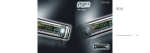
Front
I
¢0
O
Panel_
Z
_Cabinet
(front frame)
/
W
il !¸
....
d!iii!iii!i
i_
Control
• Adjustment buttons
on the bottom•
• The back
cover
indications
adjustment
panel
are located
is provided
to distinguish
buttons•
with
the
L
Indicating
• The main power
lower surface•
Main
TIA
I
VOLUME
/
UP/DOWN
buttons
_1"_- 1
(ASELECT
button)
PROGRAM
DOWM
button
buttons)
(vSELECT
) indicates
Caution
SELECT
when
button
switch
is located
lamp
at the back
I_
on the
_i_7_
[I"8_]
......
button)
:_]
the function
moving
button
(OK button)
PROGRAM
UP button
(<I_ADJUST
SUB-POWER
• (
INPUT
power
switch
while the MENU is displayed
the
main
on the screen•
unit
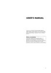
Rear
• As this product is heavy, whenever it is moved, two
people are required to transport it safely•
• Whenever the unit is moved it should be lifted forwards
rips
using the two handgdps
at the back, and the unit shoukJ
then be held at the base on both sides for stability
Handgrips
]
External
speaker
terminals
External
terminals
\\
]
External
device
_IGIT_Lm_UT
_BI
connection
A_ALOGI_PUT
_Ge2
terminals
_
I
RGB
input
terminals
[1_5-_
1
......................................
AUDIO MODE button
.........................
SURROUND button
RECALL
INPUT
SELECT
MENU
PROGRAM
UP / DOWN
button
butto
.............................................
O©
......................................
MPX button
n ..........................................................
button
buttons
...................................
MULTI PICTURE (PinP) button
...............
................................................................
Buttons for MULTI PICTURE mode
.............................................
RETURN button
.................
......................................................
.............................................
SELECT / ADJUST buttons
( A_IV' _ _ )
................................................
VOLUME UP / DOWN buttons
OK button
DVD CONTROL
buttons
.....
....................................................................
MUTE button
..............................................................................
..................................................................
FREEZE button
.................................................................
ZOOM button
©®@
PROGRAM SELECT buttons
® ® ®
................................................................................
©®@
PROGRAM UP / DOWN buttons
®
..........................................................
:
................................................................
RGB /VIDEO buttons
Loading
)
Batteries
1. Open the battery cover.
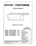
I Handling
the
Remote
Control
]
Use the remote control within about 5 m from front of the unit's
remote-control sensor and within 30 degrees on both sides.
• Slide back and remove the battery
cover in the direction of the arrow.
\,
2. Load batteries.
• Load two Size AA batteries included
With
observing the correct polarities.
in 30
With in 30
degrees
About 3m
About
About
3m
5m
3. Close the battery
cover.
• Replace the battery cover in the
direction of the arrow and snap it back
into place.
ATTENTION
_
(L_UTI[()N]
Do not use new and old batteries together.
The batteries could
I explode or leak, resulting in fires, physical injury, or stains.
• When loading batteries, observe their correct polarities as marked
on the product. If loaded in the wrong direction, the batteries
cou d exp ode or eak, resu t ng n f res, phys ca
12
n ury, or sta ns.
• Do not drop or impact the remote controk
• Do not splash the remote control with water or put it on a wet
object to avoid possible failures.
• Before leaving the remote control out of use for an extended
period of time, remove the batteries from it.
• If the remote control begins to lack responsiveness,
replace the
batteries.
• Strong light such as direct sunlight impinging on the
photoreceptor
of the remote control can cause operational
failure. Position this unit to avoid direct contact with such light.
I
¢0
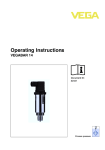
PICTURE
AUDIO MODE
MODE
You may recall the picture mode by
pressing this button. Each time pressed,
picture mode is changed in following
sequence.
Movie
PICTURE
INPUT
Press this button
INPUT
SELECT
mode.
to change
input
RECALL
AUDI(
MPX
MENU
MULTI
RETURN
MPx
the selected
PROGRAM
Press these
program
/
i
buttons
Press this button to turn off the set
I
sound.
Ii
MUTE When press again or the []
volume up button will restore the sound. I
to operate I
brand of DVD player.
SELECT
buttons to select
a TV
directly.
I
i
Press this button to change the
picture to freeze mode, Press it again
FREEZE
to
return to normal picture.
©©®
©®@
AVI
& TEXT
These buttons change Captions
between [Captions] and [Text]
d rect y, w thout us ng OSD Menu.
AV2
AV3
i
flZOOM
i
Pressthis buttoncan change Picture size.|
G1GI
C.C
i
MULTI MODE
In multi-picture mode, pressing this
button will change the multi-picture
mode,
I--
CONTROL
PICTURE
Press this button to change the
screen to multi-pictures,
Press it
again to return to normal pic[ure.
This button is for Multi-Channel
Television Sound only.
"1
DVD
,
MULT, PIC,
With this button, the display change
between "--","---","-" and AVO0 on the
top right hand corner of the screen.
"--" is for 2 digit channel selection,
"---" is for 3 digit channel selection
and -" is for 1 d g t channe se ect on.
You can use these
_1_Music
,
-IQET G @
RECALL
These buttons will turn the C.C
display on or off,
IJJ
MATRIX
SURROUND
Press this button to set Matrix
Surround On or Off.
I
C.C [ON & OFF]
Z
You may recall the sound mode by pressing
this button. Each time pressed, sound mode
is changed in following sequence.
AV4
/
I-Mode /
/
/
I
TEXT
I
Pressing this button can indicate
time by On-Screen display when
receiving
a TV program
the
I
I
on the screen, I
13
• Refer to the installation instructions
concerning
mounting of the Desk-top
The instruction
manual is included with the Desk-top Stand.
The Desk-top Stand has been used for the illustrations in this manual.
Stand.
--
---
Monitor
Desk-top
..........
I....
Use one of the special mount units to install this product.
A mount of insufficient strength or inadequate
dropping and result in fire, electrical
shock or injury. Please note that our company assumes absolutely
or property damage caused by use of other mount units or improper installation.
I
design can cause overturning
no responsibility
for personal
z_X CAUTION]
• Installation
yourself.
stand
or
injuries
10cm (4 inches)o[ more*
of the wall mount
Ask your dealer
In order to prevent
_ JJ_fff
to provide
an internal
up) or more between
blocked.(;_-')
unit and ceiling
mount
unit can be dangerous,
the name of a qualified
temperature
increase,
the sides and other objects
so do not attempt
this work
installer.
maintain
a space
such as walls,
of 10cm (4 inches
etc., so that the ventilation
: For a desktop
set-
holes are not
I
cA,:HoN
]
Have this unit mounted
in a stable place.
Take measures
to prevent
it from tumbling
down to avoid possible
physical
injury.
Securing
to a wall
or pillar
usff_g a commercially available cord, chain and clamp, secure the set to a firm wall or pillar.
C_ain
_cord
or chain
Pillar
Securing
desktop
1) Using wood screws (two), fasten the set to the clamping screw holes on the rear of the stand as shown.
2) Using
14
commercially
available
wood screws,
secure the set firmly in position.
proceeding
* Choose
to these
an appropriate
steps:
site
and
install
the
product
on a level
table
where
the
stand
3_
¢0
is secure.
.,,J
® Install the monitor to have ready access to a power socket available,
. Make sure that the power
switch
of this device
is turned
off.
(5
Z
#J
(1) Make sure that the display signal of the personal computer to be used is compatible
device.
• See "Product Specifications" concerning the specifications of this device. "-_[bb_
--'_'_'_
with the specifications
(2) Make sure that the power switch of the personal computer is turned off.
(3) Connect the signal input terminal (RGB 1 or RGB 2) on the rear panel of this device to the display
of this
signal output
terminal of the personal computer.
• Use a cable that fits the input terminal of this device and the output terminal of the personal computer.
• Depending on the type of personal computer being connected, the use of an optional conversion adapter or the adapter provided with
the personal computer may be necessary in some cases. For details, refer to the instruction manual of the personal computer or ask the
personal computer manufacturer or your local retail dealer.
Monitor rear panel
Speaker(R}
Speaker
I
(L)
connector
DIGITALINPUT
ANALOGIt4pUT
PC_
PC_;)
AUOIOI_
_
Q
_]
Power
cord
Stereo
mini jack
/o=su0/
I
terminal
_
I
3.5mm
J& To audio
H
output
_'
terminal
PC
15
Refer to the installation
The instruction manual
instructions
is included
concerning
mounting
with the Spaker Unit.
of the speaker
unit.
_ __
Connect
the power
cord,
after compJeting
',_PConnect
the power
cord to this
',_2)
Connect
the power
cord
(The type of Nug
aJJ other
Speakers
_
connections.
device.
pmugto the power outmet.
is different
from
this drawing
for some countries.}
[/6,CaUTiON
]
]
Use only the power cord provided.
I* Do not use a power supply voltage other than that indicated (AC100-240V, 50/60Hz) as this may cause fire or electric shock.
16
I
¢0
• To turn the monitor
J\
Main power
Indicating
switch
lamp
power ON, press the main power
switch on the monitor main unit to ON, and then press
I Z
IJ
the SUB POWER button or the ON/OFF button on the
remote control.
I
• To turn the monitor power OFF, press the SUB POWER
button or the ON/OFF button on the remote control, and L__
then press the main power switch on the monitor main
unit to OFF.
• During normal use, the main power switch is set in the ON
position, and the monitor can then be turned ON/OFF using the
SUB POWER button or the ON/OFF button on the remote control.
Indicating lamp
Indicating
lamp
Power status
Off
When the main power switch is
ON, and the ON button on the
remote control or the SUB POWER
button on the underside of the
front of the frame is ON.
On
button
Lights
POWER ON/OFF
button
orange
Off
(Power Save)
PICTURE AUDIOSURROU_
RECAL
M_X
MULT
PIC
O0 0 0
¢¢
When the main power switch is
ON, and the ON button on the
remote control or the SUB POWER
button on the underside of the
front of the frame is ON.
However, the state in POWER
SAVE mode
000
INPUT
is set
When the main power switch is
ON, and the OFF button on the
remote control or the SUB POWER
button on the underside of the
front of the frame is OFF.
Off
(standby)
Lights green
SUB-POWER
When the main power switch
to OFF.
Off
Lights red
Operating
When the indicating lamp lights in orange or the message "No Sync.
Signal", "Power Save" or "Invalid Scan Freq." appears on the screen,
there is something
unusual about the status of reception.
See "Power Save Mode" or "Symptoms That Seemingly Appear
Fai,uros" ]
to be
ATTENTION
• Avoid repeatedly
turning
the monitor on and off at short time
intervals. Failures might result from such operation.
• Turn off the main power switch before leaving the monitor
use for an extended
period of time.
out of
• If a power failure occurs while the main unit is running, it would
be powered on upon recovery from the failure. Turn off the unit
main power switch before leaving the main unit.
8@@
CO
1EX
RGBI
RGB2
0 000
17
The volume can be adjusted by pressing the VOL+ and
VOL- buttons of the remote control (or the • and •
volume buttons of the monitor unit).
Volume
Volume
INPUT SELECT
button
VOLUME
UP/DOWN buttons
Adjustment
setting
value
15
status guide
display
• When a button is pressed, the volume adjustment
status guide will be displayed.
• The volume will increase when the VOL+ (or A) button is
pressed while the guide is being displayed.
• The volume will decrease when the VOL- (or V) button is
pressed while the guide is being displayed.
MUTE button
The audio volume can be temporarily mute by pressing
the MUTE button of the remote control.
9®
i© ®
Volume
--
RGB buttons
Volume
setting
value
15
Adjustmentstatusguide display
colorwill change to magenta.)
(The display
• Input can be switched
by pressing
the AV1, AV2, AV3,
AV4, RGB1 or RGB2 buttons of the remote control. And
the way to return to a TV channel is as follows:
• Pressing INPUT SELECT button at RGB2 input screen.
• Pressing some PROGRAM SELECT buttons and select a TV
channel.
• Pressing PROGRAM UP/DOWN buttons at the screen without
OSD(On-screen display).
• Input can be switched in the sequence of TV -->AV1 -,
AV2 -->AV3 --> AV4 --, RGB1 --> RGB2 by pressing the
INPUT SELECT button of the monitor or the remote
control.
18
• When a button is pressed, the volume adjustment
status guide (magenta) will be displayed.
• The volume setting can be lowered by pressing the VOL- button
while the audio is mute.
• The muting can be cancelled by pressing the VOL+ button or
MUTE button while the audio is mute.
When the MUTE button of the remote control is pressed
again, the audio will be restored and the volume display
(green) will appear.
RECALL
i
OoINPUT _ECAU_ 0
button
I
¢0
_UlT_PIC_O
Z
W
--
Each time the ZOOM button of the remote control is pressed,
status will be displayed at the bottom of the screen,
the screen display
* Real mode gives the image of the same shape as it is displayed on a computer
This mode is only available for VGA (640 X 480) and WVGA (864 X 480).
Display
area
selection
diagram
Resolution
Full display
Display
Full
(RGB
area will change
ZOOM button
in sequence
and the
monitor.
input)
Circular
Real
Normal
Zoom
display
1
Zoom2
Zoom3
640 X 480
(VGA)
800 X 600
(SVGA)
1024 X 768
(XGA)
1280 X 1024
(SXGA)
1600 X 1200
* VGA
(UXGA)
only
Processes
such as compression
theflickerflicker.may
become
noticeable
(thinning)
and expansion
on Zoom (1 _ 3) depending
and W_VGA
are performed
on the display
for the above
contents.
signal display.
If this occurs,
Because
turning
of this, there is a possibility
the Vertical
Filter On _
that
can reduce
The input signal status can be displayed on the screen by pressing the RECALL button of the remote control or the monitor.
• The display wNI go out in approximately 6 seconds.
Off-timer
On-timer
_
--
- - Min
RGB
H : 48 4kHz
V : 6011 Hz
RGB2_
Signal
mode
Input horizontal frequency
Input vertical
Input
mode
frequency
19
POWER
PICTUR E AUDIO
©ooo
INPUT
RCA_
MPX
SURROUN[
OOOO
MULTPI{
cc
When the MENU button is pressed,
MEnU
RETURN
MENU button-
-- RETURN
=
,
÷
buttons
OK button
SELECT/ADJUST
buttons
the adjustment
menu
screen will be displayed; from there, PC signal adjustment
and setting is possible by using the SELECT button,
ADJUST button and OK button,
• Refer to _21]settings._ _ _
Example:
2S]
Selecting
concerning the adjustment items and the
the Picture screen
1. Press the MENU button to display the Main Menu
screen.
MENU
Audio
Timer
Setup
Language
Function
Select
Set
AV/
CO
cc
AV2
iExr
AW
AV4
© O
RG_I
OOOO
RGB2
2. Press the OK button to display the Picture Menu
screen. (Use the A and T SELECT buttons to select
other items.)
Picture
Co,,trqst
Brightrless
+31_
31
Tint
Color
Picture Enhancement
+ 31
Oft O
Color Temperature
Color Temp Adjust
Reset
Normal
€Select
Ic£_JReturrl
_Exit
3. Use the A and T SELECT buttons to select the item to
be adjusted and then use the _ and _ ADJUST
buttons to adjust (example: Contrast).
Contrast
€ Next ,' Prey
_Adjust
+ 31
_Return
• Press the RETURN button to return to the previous screen.
• If there is no operation for a period of one minute, the
Adjustment
Menu screen will be closed automatically.
2O
I
¢0
Picture
MENU
®
Audio
Timer
Function
Setup
Language
Select
Set
EContrast
G
]
Picture
+gl _1
(5
st DI
Brightness
Color
Tint
Z
IJJ
+31 _
Enhancement
Color
"Temperature
Color
Reset
remp,Adjust
-_ Select
Normal
Reset
Of[
{2 _ Return
[_]Set
Contrast
€ Next / Prey
+ 31 _
_Retum
_Adjust
--
I
Picture
Contrast
+31
Brightness
Color
Tint
+31_
Picture
3_1
I
Enhancement
I Color Temperature
Color letup,Adjust
Reset
_Se[ect
[
Normal
Reset
_Retum
[_Set
Color Temperature
_Next/Prev
_Se[ect
Normal
_Retum
Picture
Picture
Contrast
Brightness
Color
I Color
: +31
:
31
:
0
Tint
Picture Enhancement
Color Temperature
I Color %ernp,Adiust
I
Reset
Select
_
Set
Selected
characters
"_
O31 _
Normal
Narrows
Broadens
Setup
and darkness
the gap between
brightness
and darkness
further
button
The color
to magenta.
Black is subdued
increased
overafl
Color
Darkens
Tint
t
Cool
Lightens
red and weakens
Off_
Picture Enhancement
_
colors
Enhances
red.
Low-,_
Normal
Red
Green
Blue
Cut Off
Red
Green
Blue
Reset
hint
to suit the ambient
till [+40]
by pressing
for [+32]
This special
r_ _, Return
to [+40]
mode
brightness
and holding
numbers
is better
D}_ cursor
will change
for dark
setting
Adjust
to taste.
Adjust
to taste.
from
scenes.
We
is adjusted
green
and weakens
Middle _
_
Warm
This is not available to adjust when receiving
PAL/SECAM
In this case the character
will be grayed
out.
Adjust for most realistic skin color
Nigh
_
Black
Sets the clarity
of small
details
to the desired
signal
level
/ White
Normally
t
set to Normal.
Turn On when you wish
the user's preference
Color Temp. Adjustment
Amplitude
4_On/Off
Black is set off for increased
overafl brightness.
colors
Enhances
green,
Color Temperature
for
darkness,
+ 31
0_
+ 31
For brighter scene some parts of the picture might not be clear
recommend
to set at [+31].
"Panel Life" in the Function
Menu should be set to Normal when
Contrast
Brightness
visibility
This can adjust
white
On
63
0_
31
Reset
_ Select
for maximum
at [+31].
I
Reset
_
the gap between
brightness
]
Reset
Return
Adjust
Contrast
|
Temp, Adiust
Ampbtude
Red
Green
Blue
Cut Off
Red
Green
Blue
to change
color
temperature
depending
on
Brighter scene is decreased in Brighter scene is increased in
reddish
color
reddish
color
Brighter
greenish
scene
color
is decreased
in
Brighter
greenish
scene
color
is increased
in
Brighter scene
bluish color
is decreased
in
Brighter scene
bluish color
is increased
in
Dark
scene
reddish
Dark
bluish
in
is decreased
in
color
scene
greenish
Dark
is decreased
reddish
color
scene
Dark scene
is decreased
color
off the function)
in
in
is increased
in
settings
modes
color
temperature
depending
are independently
stored
on the user's
in each
preference.
of the 4 Color
These
Temperature
color
Dark scene
greenish
Adjust
is increased
color
Dark scene
is increased
in
bluish color
(waiting
to reset)
The original
restored
factory
by pressing
settings
for the items
of this
Menu
page can be
the OK button
Z1
Picture
_IENU
IAudio Mode
Treble
Bass
Timer
Function
<_
Setup
Language
#Select
Set
Audio
characters
•
•
Mode
suitable
for Movie.
the audio
suitable
for Music.
This selects
Enhances
treble
Adjust
to taste.
Bass
Suppresses
bass.
Enhances
bass
Adjust
to taste.
Balance
Suppresses
right-side
Adjust
to taste.
E_ Off _
Low -_--_ Middle _-_
Hig h _]
the audio
takes
to distinguish
between
TruBass
gives
Adjust
Matrix Surround
This features
Perfect Volume
This will
the same
(off the function)
(waiting
to reset)
depending
of the ability
bass
the spacious
automatically
average
for News,
be adjusted
two different
enhanced
tones.
sound
Talk show etc.
By using
sound
of a stadium
effects
so each
ear to be able
this ability,
that otherwise
preference
volume
on user's
of the human
on the user's
adjust
volume
]
suitable
advance
it depending
channel
would
not
and input
be
has
level
The original
factory settings
for the items
restored
by pressing
the OK button.
Picture
Audio
of this Menu
page
can be
status
when
Timer
Loffn,fiSr
On Timer
#Select
Function
MENU
should
SRS TruBass
heard
Reset
hint
the audio
treble.
sound.
Setup
This selects
Suppresses
left-side
Icy<_]Return
This selects
Treble
Suppresses
_Set
Music:
Favorite:
This mode
3reference
SRS TruBass
to K
0L_R
Middb
Off
Off
Reset
Movie:
Speech:
sound.
+tO
Balance
SRS TruBass
Matrix Surround
Perfect Volume
Reset
#Select
Selected
Movie
I
I :
SOMin
:
_: _
Fd'_ Return
,_ Adjust
Setup
Language
$ Select
Set
Selected
characters
Off Timer
•
•
-_Min.-_,_
30Min_
_-,_120Min
-_*,_
Setup
_,,_a_ 60Min_
This function
90Min
indicated
_
autornatically
time period
This automatically
On Timer
- - ( :- - )
hours
(- - : )- minutes
sets the power
to standby
the
has elapsed
sets the power
from
standby
to ON when
the
indicated
time period has elapsed.
The settable time is O0:0O_ 11:59.
Input the required
time by V A SELECT buttons on the remote
control
22
hint
I
¢0
Piclure
Audio
Timer
Function
IScreen Saver
Screen Wipe
Black Side Panel
MENU
®
Setup
Language
Select
Set
Video Power Save
Freeze Mode
Default Zoom
Reset
Selecl
Selected
characters
_11
I
Standby WMte
Gamma
Reset
Oft
22
Reset
intervals,
stationary
Screen Saver
the picture
This is used
stationary
On
60Min.
Panel
Off _
to reduce
pictures
screen
On _]
Optional
(grayed
out)
Default Zoom
Optional
(grayed
out)
the Contrast
Normal
_
Extend
1_
Extend
2
This can display
off _
mode
On
and signal
60Min.
watching
is changed
mode
when
can be
regardless
control,
of
power
of a panel can be
consumption
to Normal
the Input
By this
image
page
of the screen
Menu
mode
powered
the panel
of this Menu
or degradation
of power
normal
the monitor
is Extend
this
2 < Extend
1 <
item is set to Extend
1 or
automatically
Signal
Screen
Display
every
time the input
are changed.
Screen
Display
is not needed
when
can change
each
level of RGB
signal
invert to reduce
the panel image retention.
When this function is required
to use,
select On (continuous
operation)
or 60Min. (time limit operation)
and
press
the OK button.
This function
And
press
is also provided
the Menu
against
or Return
the image
button
retention.
to exit.
If time is
set for this item, the screen changes
into the white pattern when the
monitor enters power save mode, and it will continue
for the period of
setting
Garnrna
with
On (continuous
signals.
This function
On
White
visible
Assigns
ID nos. to the monitors so that they can be controlled
individually
(up to 7 monitors can be controlled).
ID Number
Standby
when
the contrast
in the Picture
Set to OFF if the Input Signal
switching
Inverse
at set
that can occur
Select
to set to Off to reduce
setting
2, it will be changed
F_
retention
set to Off when
can be reduced
The order
If the Contrast
Mode Display
On/Off
is to suppress
setting
consumption
mitigated
Normal.
t
image
field signal
The original factory settings for the items
restored
by pressing
the OK button.
to reset)
This function
Panel Life
sidebars
It is always
On. [t is recommended
retention
Freeze Mode
(waiting
the panel
by the white
size area.
Optional (grayedout)
(off the function)
in small amounts,
viewing.
Video Power Save
Reset
hint
the screen
have disappeared.
This turns the gray
Side
Return
operation)
or 60 Min. (time limit operation)
and press the OK button.
Press the MENU or RETURN button on the remote control to return to
normal
Black
around
_
to reduce the panel image retention.
This is where
objects,
such as screen Iogos, leave a slight image
after they should
Screen Wipe
<_*Set
Setup
This moves
Normal
Off
1
On 60Min
_.
UJ
Split
Panoramic
Reset
i_
Return
Mode Display
ID Number
Inverse
Select
Z
Off
4_-Set
Functior_
[Panel Life
tD
Off
On 60Min
Off
I
Normally
time.
set to 2.2
23
Pb_ure
Audio
Timer
Functbn
FHorizontalPosition
Vertical
Position
Auto
Adi_st
Horizontal Clock
Clock Phase
Reset
tt_Select _Retum
Language
,_Sele_
D_S_
[
o
+ 31
Adjust
20
10
Reset
[_Exit
Horizontal Position
# Next / Prey
I
I
i
i
Setup
Auto Adjust
Horizontal Position
Vertical Position
Horizontal Clock
[ Cloc14Phase
Reset
_,Se[ect _Ret_rn
Adjust
0
+ 31
20
10
Reset
[_]Exit
J
Clock Phase
characters
Setup
Auto
Adjust
Adjust*
Horizontal
Position
Pressing the OK button here,
Automatic
regulation is started,
Moves the horizontal
:0 left,
Vloves down
sos tion,
position
Moves
the horizontal
Moves
up the vet
Vertical Position
the dot
:requency
clock
(shrinks
Increases
the right
sde).
Horizontal
the
freq Jency
Reset
the dot clock
(shifts
slightly
Advances
phase
to left),
(stifts
the
dot clock
sl ghtly to r ght).
(of
the function)
(wai
hint
Position,
automat
Horizontal
Clock
and Clock
cally.
AdjusL the left-side display position,
This functior" is only for RGB2. It's not available
(grayed
out) for RGBI.',
Adjust the vertical display posilion.
This function is only for RGB2, It's not available
(grayed
out) for RGB1.
Adjust for maximurr
character
clarity.
This function is only for RGB2. It's not available
(grayed
out) for RGB1.]
(grayed
out) for RGBI.',
Dhas_
Adjust
for clear
This function
The original
ng to reset)
Input Level
Frequency
are adjusted
Vertical
the rght
side),
Slows
Phase
Position,
dot clock
(expands
Clock
Clock Phase
Horizontal
cal positiorl.
[]
Reduces
_Return
position
to right,
the vertical
_* Adiust
o.7v
off
of 1
off
on
Movie
DVI PC
RGB
Return
Input Level
Flequency Display
WVGA Type
WXGA Mode
Vertical Filter
Frequency Mode
Setup
RGB1
RGB2
#Select
__Set
(Met u)
10
Next / Prev
i
Selected
0o___
_ Adiust
character
vis bil ty.
is only for RGB2. It's not available
factory
settings
for the items
restored
by press ng the OK button.
Normally
set to 0.7 V. If white
of ths
(rhis
is four'd
Menu
is effective
to spread
page
can be
only for RGB2.)
across
the screen,
set to 1.0 V. (This s effect ve only for RGB2.)
Set this to Off if the frequency
Display
Display
nformation
This is orfly available for W-VGA
When it is set to On, the display
WVGA Type
of the Input Signal
Screen
is not required.
signal
area mode
can be selected
Full or
Real.
Off _
WXGA Mode
1280x768_
Mode
This is only available
selected [1280x768]
f
-,,-,-on-*-q
Vertical FiRer
Frequency
1366x768
t
[-_ Movie_
Turp On when
PC
F_ RGB-_=_
Componenl
Depending
screen
moving
[-_ Auto _
on the type of signal displayed,
H DTV _
displays
SDTV/DVD
47
may not be optimized
should
siqould
be set
correspond
only
mages
when
to the
area mode
is
flicker,
or/a
This should
correspond
to the signal
mode
the equipment
that is connected
to RGB2 D-sub
_7
This step
!st step.
Z4
v ewlr'g
about
1he display
personal
]his
should
correspond
to the signal
mode of the
the equipment
that s connected
to RGB1 DVI terminal,
Ths
RGB2 (2nd step)
concerned
Set to Movie when
RGB1
RGB2 (1st step)
for (PC) WXGA signal,
or [1366x768].
[Component]
signal
mode
computer,
sgnal
from
of the signal
terminal
from
is selected
of the
signal
on the
from
the equipment
that is connected
to RGB2 D-sub termirla[
Normally, set this to Auto. The signal mode of the input signal will be
automat cally recognized.
If the input signal contains much noise or has a low level at Auto an_
the operation
is found erratic
set this to match the input signaJ
throu( h automatic
adjustment.
Adjust
manually
to optimize
them.
J
I
¢0
Piclure
Audio
Timer
Function
Setup
MENU
iL_n_u@d
®English
€ Select
_Set
Select
a language
Approximately
by • •
1 sec. after adjustment
Menu
Picture
SELECT buttons
Display
€Select
is completed,
the adjustments
condition
For every input function,
is registered
Brightness
Z
o Espa_oJ
IJ
_Returrl
_Exit
1 setting
will be recorded
Menu
Display
Function
Screen Saver
as shown in the table below.
Registration
setting
Screen Wipe
(not registered)
Black Side Panel
(not registered)
fint
Panel Life
Picture Enhancement
Mode
Color temperature
ID Number
Standby
G Amplitude
For every Color Temperature,
setting is registered,
1
Setup
Iterizontal
B Cut Oft
Bass
(not registered)
Position
Clock
setting
is registered,
For every Audio Mode,
°egistered,
is
Mode,
1 setting
is
(Only for RGB2)
Clock
Phase
Input level
1 setting
For every signal
"egistered
Vertical Posidon
G C'ul Off
Mode
Auto Adjust
Horizontal
R Cut Off
Treble
White
Gamma
B Amplitude
Audio
is registered,
Display
Inverse
AcJjust
R Amplitude
setting
condition
is registered
Color
Color ]emp
Audio
o FraBgai9
and press the OK button.
Registration
Contrast
]
Frequency
setting
is registered,
setting
is registered,
Display
WVGA Type
Balance
setting
is registered
WXGA Mode
SRS TruBass
Matrix Surround
Perfect Volurne
Vertical Filter
For every Audio Mode, 1 setting is
_egistered
Frequency
Mode
Language
• The previously
recorded
items will be lost.
• The signal mode can be identified by the horizontal/vertical
sync
frequency
and the sync signal polarity. Different signals with which
all the elements are the same or similar will be handled as the
same signal.
25
Changes in the signal status are displayed on the screen as they arise.
Status
When
Mode
Display
is set to ON,
A guide
terminal
the input signal is switched
or
when the RECALL button is
RGB
Action
Display
is displayed
for the input
and the horizontal
and
vertical
RGB2
RGB
H : 48
6014kHz
Hz
V:
sync frequency
pressed.
r(_
When the sync signal
detected
is no longer
• A guide
displays
No Sync.
Signal, and Power
approx. 5 sec.)
• When the condition
where
the sync
detected,
power
source
orange
connection
A guide
Freq.
save
displays
status
continues
signal
cannot
lamp
changes
and the mode
to power
When the input signal does not
match the monitor specifications
or is in an unstable
status.
Save (for
indicator
- - lVlin
Recheck
the personal
computer
power switch status and the
be
! No Sync
of
Signal
in
switches
mode.
Invalid
Scan
Recheck
the input
specifications.
signal
! Invalid Scan Freq
When
• when
the RGB1,
RGB2
this unit is connected
computer
is not being
input
is selected
to a VESA DPMS computer,
used to reduce
power
the Power Save (Off) mode can be set to be activated
consumption
automatically
when the
by this unit.
/
RGB sync signal I
Horizontal
/
PC
Vertical
signal
Active
Operation
mode
Indicating
lamp
Yes
No
Yes
No
Yes
Yes
No
No
(normal
display)
Blank
On
Lights
display)
Off
green
Lights
3W
Power consumption
(no
310W
or less
orange
(RGB1)
1W or less (RGB2
3W or less (RGB2
; 100V_AC<_120V)
; 120V<(AC_240V)
Returning
to operating
status
• Operate the personal computer, or press either the INPUT SELECT button of the main unit or the RGB1/RGB2 buttons of the remote control.
26
There are different characteristics that result in panel image retention depending on how the plasma display is used.
Situations and effective usage methods related to ghosting are provided below.
I
Image retention characteristics
of a plasma display
The image retention phenomenon of a plasma panel occurs due to partial phosphor degradation arising from partial character and figure
display.
C5
Z
_d
i
For example, when the character image as shown in Fig. A at the right is
continuously
displayed for a long period of time, the only part of the phosphor
(Red,Green,
Blue) that will degrade will be the color of the applicable
character
display portion. Consequently,
when a white image is displayed
on the entire
screen as shown in Fig. a, the character marks displayed
up to that time will
become a color difference visible to the eye, but the phosphor wNI never burn.
raThe degree
of image retention
• The tendency
and figures
brightness,
of the phosphor
is proportional
to the brightness
is to degrade
more the brighter
at locations
and figures
displayed
as well as the display
when the brighter
time.
i_iiii,%iiitliiiiiiiiiiiiiiiiiiii_iiiiiiiii
the characters
are displayed. When images of figures with different levels of
as shown in Fig. B, are continuously
displayed
for a long period
time, it becomes easier for image marks
are displayed
to be noticeable.
[Fig. al
[Fig. A]
of the characters
of
figures
[Fig. B]
* The image
retention
is seen differs
Methods
images
depending
to Reduce
the
in this document
on the operation
Occurrence
are exaggerated
for the purpose
of explanation.
(Refer
to reduce
retention
of
Image
Using this function
makes
Retention
degradation
of the panel.
1.or Extend
monitor to an "Screen
2 shown on _:i_
can be made using Screen
• Using in combination
Since the degradation
Wipe"
or "Inverse"
display.
Wipe and Inverse
with moving images
of the fluorescent
material
of Function
progresses
screen
MENU
comparatively
retention can be controlled. We recommend
to use in combination
* Please be careful since image retention will occur if display is left
* Television broadcasts
include images displayed for long periods
broadcast station name or time are displayed for a long period of
be expected to occur, so please be aware.
About
it
)
The occurrence
of image retention when displaying
images of identical patterns, such as static images, for long periods
reduced
by displaying
a reversed color or completely
white screen for about 1 - 2 hours after terminating
the display.
(Settings
b]
in which the image
image retention.
to Panel Life (Extend
• Set the plasma
[Fig.
The actual manner
time and brightness.
• Lower the Contrast and Brightness settings of the plasma display as much as possible.
A function is provided in the display that controls the brightness
of the screen to reduce
possible
:
of time can be
shown on I-2_31 )
uniform for moving
images,
the occurrence
of partial
image
with moving images such as a DVD.
in a two screen display state for a long period of time.
of time in which the left and right or top and bottom of the image are cut and
time at the same portion of the screen. Image retention in these portions can
defects
• High precision technology
(points that are too bright)
is used in the making of plasma panels but there may be dark spots (points that do not illuminate)
in some cases. These do not indicate a malfunction.
and bright
spots
About residual images
• In some cases, residual images may remain after the short-term display of still images and another image is displayed, but these will
disappear and return to normalcy. This is not a malfunction.
About the panel screen
• Plasma displays display images by means of electrical discharges inside the panel. Because of this, the temperature of the panel surface may
rise in some cases.Also, plasma displays are made of finely processed glass. A reinforced glass filter is installed over the panel surface but
avoid strong impact because there is still danger of glass breakage.
27
Make the checks
Customer
suggested
servicing
below
depending
on the symptoms
observed.
If the symptoms
• The message "No Sync. Signal"
Save" is displayed.
lamp
• Check the way the power
• Press the power switch.
or "Power
• The display
slantwise.
your dealer.
"Invalid
indicating
Scan Freq."
image appears
is connected.
equipment,
• Make sure the computer is not in the power-save
mode.
• Check to see if the input selection matches the connection
terminal.
An input signal is not received normally.
• Check to see if the input signal matches the monitor
specifications.
• Check the way the signal cable is connected.
is
lamp is normally
cable
See page
No sync signal is detected.
• Check the way the signal cable is connected.
• Make sure that the switch of the computer,
imaging
etc., is turned on.
• No picture with the power indicating lamp
lights in orange.
• The power
no picture.
contact
Point to check
with the power-indicating
• The message
displayed.
uncorrected,
can be hazardous.
Symptom
• No picture
off.
remain
lit but
• Check the contrast and brightness
settings (adjust them for higher
contrast and brightness).
• Check the way the signal cable is connected.
flowing
• Adjust the dot clock frequency
and phase.
frequency
first, the dot clock phase next.)
(RGB input)
• Text displayed
across the screen appears
vertically streaked, with the characters
in
vertical columns blurred.
• Text displayed
across the screen appears
blurred.
• A fine pattern flickers when displayed
on the
7
• Adjust the dot clock
(RGB input)
phase for the clearest
(Adjust
the dot clock
viewing.
_2_4_
screen.
• The remote
1-30_1
control
does
not work.
• Check
to sea
if the batteries
opposite direction.
• Check to see if the batteries
28
_'_4
_-21_
are loaded
in the remote
control
in
_i]_
in the remote
control
are OK.
I
¢0
Point to cheek
Symptom
are locations
on the screen
that are different
periphery (*),
_PcinLs that do not light, points wkh brightness
from that of the periphery,
that of the periphery,
etc,
Vertical
stripes
appear,
depending
The plasma display panel is lighting lhe phosphors
by the
discharge
of internal radiation.
In some cases, this may cause the
temperature
of the panel surface to increase, Please note that this
is not a malfunction,
from t_
different
points with color different
on the screen
Z
IJ
The temperature of the display panel surface is high,
_,There
O
See page
frcm
contents,
,, High-precision
technology
is used to manufacture
the plasma
display panel, However in some cases, there are minor defects
some parts of the screen, Please note that Ibis is not a
malfunction,
,, The plasma
display
panel
is lighting
the phosphors
in
by the
discharge
of internal radiation,
Depending
on the screen
contents, in rare cases this may cause vertical stripes to appear
because of failure to light, Please note that this is nota
malfunction,
_,Coarse
,' Flickering
down,
horizontal
stripes
in the form
appear
of horizontal
in PULL display,
lines oscillating
,, Adjusting
the Clock
(RGB input)
up and
(PC INPUT MODE only)
Phase will reduce
the horizontal
stripes,
® If the direct frequency
from the computer is below 85Hz, try a
higher frequerlcy
(upper limit 85Hz), There may be a slight
attenuation
of the current image,
,, -Fry Lurning the Verlical Filter On, For this case however
vertical resolution will drop,
_,The fan motor is noisy,
(Fan application
model only)
" Use the fan that controls the temperature
in the main body to
lower the temperature
of this unit, If the ambient air temperature
increases, the fan will start, the RPMs will increase and motor
noise will grow louder,
_,The top of the monitor
_'Text characters
heats up,
are displayed
the
This is not a malfunction
though,
,, When used for long periods of time, the top of the monitor
heat up, This is not a malfunction,
with varying
thicknesses,
may
,, -[he thicknesses
of characters
and lines may vary if images witha
vertical resolution greater than 480 lines are displayed;
however,
this is not a malfunction,
,, The brightness
enough,
contrast
in the display
seems
not bright
The ambient temperature
of the monito_ may be low, When used
in the arrlbient temperature
less than about 15 degrees, it may
cause lower luminance.
It happens in an operation of the panel
protect circuit, and this is not a malfunction,
The luminance will
recover by turning on electricity for a while,
®The brightness
enough, (RGB
contrast
input)
in the display
seems
not bright
_' Setup-Frequency
in RGB inpul may be set as PC mode, When set
as PC mode, the luminance
becomes lower about 10% than it is
set as Movie mode. This is not a malfunction
though, If you do not
mind flickering
on the display, please use in Movie mode,
r_'A-]
L_5_j
29
Depending
adjustments
Symptom
on the kind of system equipment
used,
suggested
bemow. (onmy for RGB2)
1
images
may not be dispmayed
Text displayed
across the screen appears vertically streaked,
The display image appears flowing (figure 2) (RGB input),
Figure 1
jv;3,t_£
normally,
with some characters
h this case, make the
blurred
(figure
1).
_I_1,20_?_
ale blu _ed
Example
._ _o_
Afte ad ustment
A ¢l_acters
_e
blurred
1)
2)
3)
4)
Press
Press
Press
Press
the
the
the
the
MENU but[on. The Main Menu will be displayed,
V SELECT button and Select Setup,
OK but[on. The Setup Menu will be displayed,
T SELECT button and select Auto Adjust,
When adjustment
is not possible with Auto Adjust
5) Press the MENU button, Ihe Main Menu will be displayed,
6) Press the T SELECT button and select Setup,
7) Press the OK button, The Selup Menu will be displayed,
8) Press the T SELECT button and selecl Horizontal Clock,
Adjustment
procedure
(Display fine patterns as characters or a vertical striped paf[ern over the entire screen during Horizontal
9) Press the I_. or _t ADJUST buttons and search for clear characters over the entire screen,
10) Perform adjustment
for symptom 2 below, when the characters are blurred on the entire screen,
The display
Symptom
image
2
may be momentarily
disturbed
during
clock
adjustment
adjustment,)
but this is not a failure.
Text displayed
across the screen appears blurred in its entirely
A fine pattern flickers when displayed
on the screen (figure 3).
(figure
Figure 2
Figure 3
Before
Clock
_djuslmen
2).
Bef°readi_stment
HHHHHHHHHHHHHHHHHHHHHHHH_,'_
_d_ABC_FGa_ca
Example
Aflef
A_ter_dju_tmen_
adiustrnom
@
1)
2)
3)
4)
Adjustment
procedure
Press
Press
Press
Press
the
the
the
the
MENU butlon. The Main Menu will be displayed,
_ SELECT button and Select Setup,
OK button. The Setup Menu will be displayed,
_ SELECT button and select Auto Adjust,
When adjustment
is not possible with Auto Adjust
5) Press the MENU button, The Main Menu will be displayed,
6) Press the _ SELECT button and select Setup,
7) Press the OK button. The Setup Menu will be displayed,
8) Press the _ SELECT button and select Clock Phase,
(Display
fine patterns
9) Press _
or _
clean across
3O
as characters
ADJUST
the screen,
buttons
or a vertical
striped
pattern
to make the text appear
over the entire screen during
9) Press _
or ._ ADJUST
without flickering,
Clock
buttons
Phase adjustment,)
to make the text appear
I
¢0
(3
Z
LU
(1) Make sure that the power switch of the monitor is turned off.
(2) Make sure that the power switch of the imaging device is turned off.
(3) Use a commercially available cable and connector to connect the signal input terminal on the rear panel of this
device and the signal output terminal of the imaging device.
Monitor rear panel
Speaker(L)
INPUT(AV4)
SeAmT
8u}_¥ lr _']o_Sq _.........
_,
l©0
...............
:b .................] ,_>
I]
Ib_ /_.=
_1/!_
_ _1
I"
DVDplayer
Set-TopBox
J
"_
VCR
S-videoiComposile
}
video
Do not connect both
plugs at the same time
Use either of them
_g
_
Use if the
vidao
equipmanl
has an
S video
inputlerminal
With DVI-STB and RGB component setup
• If video equipment with an S video output terminal is used, cabling
by the S video cable is recommended
to provide finer video
quality. (If the S video input terminal and the video input terminal
of AV3 connect to the monitor at the same time, S video input
would govern.)
• If the OUTPUT (MONITOR) terminal is connected to an external
monitor with a 75 Ohm terminal, it is possible to view the same
image as on the main unit. But it is possible to monitor only the
composite video signal from AV1, AV2, AV3 or AV4 input that is
displayed on the screen at the time.
• If the adaptor is applied to AV4 input as shown in the drawing, it is
impossible to receive RGB signal.
Tooomponen
J
equipments.
Please use the connection
cable suitable for the terminal
form of video equipment.
Applicable
video
signals
Terminal
for each
Signal
CVBS
AV t
0
<}
AV2
O
©
AVS
O
C'
AV4
0
O
RGB1
RGB2
input
terminal
Component
(See PRODUCT SPECIFICATIONS
DVl
RCA/SCART
S-video
[An example of connecting video imaging devices]
RGB
PC
D-sub
STB
RGB
Component
©
©
©
)
[_S'___
Remarks
©
©
for details.
©
Refer to Setup
Menu. [-#1
Refer to Setup
Menu. i-<81
Refer to Setup
Menu. It_9]
Refer to Setup
Menu. _3_
(O : Available)
31
--
INPUT
SELECT
ZOOM button
button
RGB/VIDEO
buttons
• Input can be switched by pressing the AV1, AV2, AV3,
AV4, RGB1 or RGB2 buttons of the remote control, And
the way to return to a TV channel is as follows:
• Pressing INPUT SELECT button at RGB2 input screen.
• Pressing some PROGRAM SELECT buttons and select a TV
channel.
• Pressing PROGRAM UP/DOWN buttons at the screen without
OSD(On-screen display).
• Input can be switched in the sequence of TV -_ AV1 -_
AV2 _ AV3 --> AV4 _ RGB1 _ RGB2 by pressing the
INPUT SELECT button of the monitor or the remote
control.
Each time the ZOOM button of the remote control is
pressed, the screen display size will change in sequence
and the status will be displayed at the bottom of the
screen.
• During
(set
VIDEO
to
signal
[DVI-STB])
input
and
(AV1,
RGB2
Full _
AV2,
(set
Cinema
to
AV3,
AV4,
RGB1
[Component]))
_--
• The size will fix as Full mode and not change when receiving
component
signal of 1080i/50, 10801/60 or 720p/60.
the
Full
Display
size
selection
diagram
When you want to
Set the display
Play a 4:3 image
in a 16:9 screen
faithfully
Play a 4:3 image
in a 16:9 screen
with
height
of the middle
and width
screen
both
enlarged
sides
on equal
appearing
4:3
and with
Panoramic
Cinema
size
image
vertically
on both
sides
• The 4:3 image is called a letterbox
image.
• In some cases, some slight blanking
remain
In some
Cinema
remain
may
at the top and bottom.
cases,
some
at the top and
slight
blanking
may
bottom.
(Oinema)
Play a 4:3 image
in the standard
horizontally
occurs
signal)
in the 4:3
on the 16:9
screen
32
(4:3
(Vista)
expanded
Remarks
screen
Blanking
Zoom
screen
Play a 21:9
Display
enlarged
Play a 16:9 VISTA size image in the 4:3
image faithfully reproduced
on the 16:9
image
Input signal
the
of the
scales
somewhat
size
faithfully
vertical
squeezed*
in a 16:9 screen
size and
An image
Full
shrunk
(Squeeze)
with
an aspect
horizontally
4:3 screen
ratio of 16:9
to 4:3 to display
in a
Vertical
picture
position
can be adiusted
for [Panoramic],
[Zoom]
1, Press ZOOM button and A T SELECT buttons during picture
2, Position display will appear
3 Adjustment range of each picture size are as shown below
[Panoramic]
- 12 to + 12
4 When
1080i/50
[Zoom] arid [Cinema]
or 1080i/60 component
signal
and [Cinema]
mode as follows
size display
- 31 to + 31
is received, vertical
position
can be adjusted
only one step up
I
¢0
(Tile range: 0 to +1)
I
Position
Z
UJ
+ 31
Press A
Press T
ATTENTION
Using
a wide=screen
monitor
,, This monitor has a screen mode selection
feature.
If an incompatible
screen mode is selected
to play certain
software,
such as a -bd program,
the image would appear different from the original Take this into consideration
when making screen mode choices,
®Use d this monitor in its enlarged display mode with the wide feature enabled in coffee shops, hotels and other establishments
commercial
or pubic viewing purposes could infringe on the copyright holder's right protected by Copyright
Law.
®When a normal 4:3 image is displayed over the entire screen in the Panoramic
mode, parts of the periphery
and/or appear distorted in some cases. Use the 4:3 mode to view images, which were created in 4:3 mode
This mode allows 4:3 content to be viewed without picture distortion
of the image
for
may disappear
33
If the PinP button on the remote control is pressed MULTI
PICTURE will display.
Activating the P-in-P mode from the RGB input screen ]
Pressing the PinP button one time will display 2 pictures.
• This mode can be available
input.
from RGBI(DVI-PC)
and RGB2(RGB)
• The speaker icon can be shifted up and down by pressing the A/B
button; the audio of the video will be output from the side on which
the speaker icon is located.
• The sub-screen
position can be
selected up and down by pressing
'_ & SELECT buttons.
powE_
_ICTURB AUDIOSU_OUN_
@O00
Oc_
A/B button
R_CAL
0
NUL
Q
MEnU
PinP button
RECALL button
PIC _
status that the speaker icon appears
on the left side of AV_ as shown in
the diagram
nETUn_
RETURN
=
to the right.
• Pressing the PinP button again or the RETURN button will cancel
the 2 pictures display.
• "Frequency
Mode" in the Setup Menu should be set to Movie when
button
VOL
sub-screen
SELECT
@/AVl
• The sub-screen
can be selected with
the AV1, AV2, AV3, AV4 and TV
channel number buttons from the
is the component
signal
of 1080i/50
AV1 : Displays
button
the
VEDEO input
or 1080i/60.
signal
of the sub
screen
Activating the Split mode from the video input screen
Pressing the PinP button one
time will display 2 pictures.
E
• The speaker
icon can be shifted
@__
J
[_
left
and right by pressing the A/B
button; the audio of the video will be
output from the
speaker icon is
• The same video
be selected for
@
®
side on which the
located.
input mode cannot
both screens at the
same time.
• Pressing the PinP button
the 2 pictures display.
2 Pictures
AV1
AV2
AV1 _AV4
AVl,AV2
PAL-N
NTSC-M
PAL-M
576i
576p
480i
480p
PAL-N
NTSC-M, PAL-M
O
O
©
O
O
0
0
0
0
0
O
0
0
0
576i, 576p
O
O
480i, 480p
O
O
O
O
O
O
O
O
O
O
O
O
O
O
O
1080i/50
1080i/60
RGB1
720p/60
STB
RGB2
Component
button
will cancel
• When the Video input is set to RGB Video, this Split mode is not possible.
• Refer to the table for 2 pictures (Split) mode.
(Split)
input terminaF
AV1
_AV4
again or the RETURN
RGB1
RGB2
STB
Component
1080i/50 1080i/60 720p/60
(O : Available
NOTE
• Even if the input of the horizontal / vertical synchronizing signal (or video signal) stops in the MULTI PICTURE display, the mode will not
change to power save mode.
• Please be careful since image retention will occur if display is left in a MULTI PICTURE display state for a long period of time.
The input signal status can be displayed on the screen
by pressing the RECALL button of the remote control or
the monitor.
• The display will go out inapproximately6 seconds.
34
_
g_._
Input mode
v,o
Off-timer
On-timer
Signal mode
I
¢0
Picture
Audie
Timer
HSNU
®
+31
_
Funolion
Bdghmess
Sl
D
Setup
Oontra_t
Colo_
Sharpness
0
+15
_
_
L&nguage
Selec
Set
Tint
Oolo_ Tomperature
LS÷t
Oontra_t
Mode
I
(5
Z
#J
0 _
No_mal
Day
Normal
Reset
Reoet
piotuce Mode
,$NextPrev
[_Returl_
4_8eleot
I
I
I
I
Cot t ast Mode
Picture
]
CNR
Film Mode
PAL
LTI
Comb
Nomal
,_NexsPrev
4_Select
[oY_Retufn
YNR
_NexsPrev
_Select
Off
_Retufn
Day
off
Off
On
Filte_
On
Off
OTI
m,lb,-
Off
Black
Eilhanc÷ment
Off
Auto Colo
Reset
_ Select
Off
Reset
[_}_Set
[_Retum
!
I
I
!
PiyNR
......
_y
ONR
Film
PAL
Day
_Return
Off
Mode
Comb
01/
On
Filte_
LTI
OT]
Off
Off
Black
Enhancement
[Auto Cole
Reset
_ Seleot
Off
]
Off
R_et
[_]Set
Picture
[_:_2_Ret
Auto
u fl_
Oolor
Off
CNextPrev
4_OnOff
_Retum
Day
Oolo
Man
Oolo
Decoding
gemerlt
Picture
Day
0o_o_ _mp
Adjust
0o_o_ De_od_n_
_e_
[_Z_]_e_
Picture
0olo[
_R_n
Day
T_mp
Adjust
0o_o_ Managemeni
€Select
_Set
RGB
Red
Green
Color
T_nt
_Return
o
R
Picture
Reset
¢Select
o G
OD
+ 60_
O_
+ Sl_
o
B
Reset
_Return
_Exit
35
Selected characters
Picture
"<I
_-
Setup
Mode
Adjust
Narrows
Contrast
the gap between
Broadens
and darkness
brightness
brightness
the gap
between
and darkness
for maximum
Black
is subdued
Brightness
increased
Color
Darkens
for
Black
darkness
overall
colors
Sharpness
Soft
Tint
Enhances
green,
Color Temperature
overall
further
button
at [+31].
The color
white
to magenta.
_
Normal
colors
Warm
green
_
and weakens
Black
t
This special
setting
Adjust
to taste.
Adjust
to taste.
is better
_j_ cursor
will change
for dark
Auto _
Shift to the minus
picture.
This is not available
to adjust when receiving
Then the character
will be grayed
out.
Adjust for most realistic skin color
Normally
from
scenes.
(-) side for a softer
PAL/SECAM
signal
set to Cool
the differences
improve
t
numbers
is adjusted.
Dynamic:Emphasizes
Normal _
to [+40]
mode
brightness
and holding
/ White
X
Mode
by pressing
for [+32]
Normally set to Centre position
effect and plus (+) for sharper
Enhances
red
_
to suit the ambient
till [+40]
brightness
Sharp
Cool
ambient lighting.
conditions
For normal viewing we recommend
that the Contrast is set to [+31].
"Panel Life" in the Function
Menu should be set to Normal when this
is set off for increased
Lightens
red and weakens
visibility
This can adjust
Contrast
Contrast
hint
Day: This setting is best for very bright
Night: This setting is for normal lighting
Dynamic
Normal
the feeling
: The gradation
possible.
Auto:Detects
image
between
video
shadings
to
as faithfully
as
of contrast.
of an image
brightness
is reproduced
and automatically
adjusts
for natural
brightness
Reset
(off the function)
YNR
(waiting
Off _
Low _
The original factory settings for the items
restored
by pressing
the OK button
to reset)
bligh
t
CNR
Performs
picture
Performs
color
And
signal
signal
it will be fixed
On:Automatically
reproduces
Film Mode
noise
noise
Turn up to reduce
DVI-STB
film material
can be
noise
noise.
mode.
and faithfully
film image.
switching
This is available
only when
to reduce
the discolorations
page
Turn up to reduce
selecting
the movie
the edginal
Off:Set to OFF when
natural
PAL Comb Filter
reduction
reduction.
as Off only when
detects
of this Menu
between
images
does
not appear
receiving
a PAL composite
signal.
in fine picture detail and provides
Turn On
purer
color
LTI
Adjusts
the sharpness
of the picture
CTI
Adjusts
the sharpness
of the color
Black Enhancement
Adjusts
the black
This is available
Auto Color
This monitors
levels.
It also maintains
Red
Amplitude
Green
Blue
Red
Cut Off
Green
Blue
36
the user's
Brighter
reddish
scene
color
is decreased
in
Brighter
reddish
scene
color
is increased
in
Brighter
scene
is decreased
in
Brighter
scene
is increased
in
greenish
color
greenish
color
is increased
in
Brighter scene
bluish color
Dark scene
reddish
in
is decreased
in
is decreased
in
color
Dark scene
greenish
color
Brighter scene
bluish color
Dark scene
reddish
color
Dark scene
bluish
is decreased
is decreased
in
in
is increased
in
color
Dark scene
greenish
Adjust
is increased
color
Dark scene
bluish color
is increased
in
settings
modes.
receiving
and adjusts
natural
an NTSC
the color
flesh
composite/S.Video
to maintain
tones while
constant
preserving
color
fidelity
of
colors
Turn On when
Color Temp. Adjustment
signal
level compensation
only when
signal
background
signal
you wish
to change
color
temperature
depending
on
preference.
color
temperature
are independently
depending
stored
on the user's
in each
preference.
of the 4 Color
These
Temperature
:1=
t.b
Selected characters
Setup
r
Color Management
Magenta
Red
Magenta
off
is weakened.
Turn On when
on
Magenta
depending
balance
of each
color
is required
IJ
is strengthened.
Red is strengthened
Yellow
Yellow
is weakened.
Yellow
is strengthened.
This adjusts listed colors individually
to make them either deeper or
more pure. These settings
are independently
stored in each of the 4
Green
Green
is weakened
Green
is strengthened
Color
Temperature
Cyan
Cyan
Select
the single
is weakened
Cyan
Blue is weakened.
Blue is strengthened.
level individually
to RGB
Press
Red
Darkens
red only.
Lightens
red only
Green
Darkens
green
Lightens
green
only.
only
mode
Tint
Enhances
colors.
Lightens
red and weakens
green,
Enhances
colors
This adjusts
green
each
color
screen
depending
every
R/G/B
when
that is required
on the user's
that indicates
the OK button
the user's
Darkens
modes.
is strengthened
Color Decoding
Color
Z
to adjust
preference.
Red is weakened.
Blue
1 item is added
the original
on the user's
hint
all color
of the 4 Color
These
settings
Temperature
R/G/B
And set it back
after adjusting.
time the setting
level or tint to make
preference.
to adjust
preference.
is changed
the color
appear
are independently
natural
for
stored
in
modes.
and weakens
red.
to the Menu shown in the page _2_31_.
Picture
Audio
"rimer
Function
[,Screen
Saver
MENU
® ---,-
Setup
]
Off
On 60Min
Off
Off
Screen Wipe
Black Side Panel
__,1_
Video Power Save
Freeze Mode
Default Zoom
Reset
Language
Select
_Set
Select
Split
Panoramic
Reset
<_ Set
Return
Function
[Panel Life
Mode Display
ID Number
Inverse
]
Normal
Off
1
On 60Min
Standby White
Gamma
Reset
_ SeJect
<_Set
Selected characters
_Return
Setup hint
This is used
Video Power Save
Off
22
Reset
is no video
mode
when
to reduce
signal.
power
Setting
consumption
it On will leads
the AV input with
no signal
for video
the monitor
input when
there
to the standby
is selected
37
Setup
Syslem
Audio
Timer
Funclion
_
_'_ENU
®
Setup
System 2
AV1
AV2
AV3
AV4
Video Input
,_
SeJect
I [])K]Set
icture
Audio Input
Scar[ Output
RGB1
RGB2
_Seleel
Monitor
DVI STB
Component
HDTV
_JReturn
[Z_D Set
Selup
System
Color System
_Exit
Setup
AV1
AV2
AV3
AV4
Monitor
DVl STB
Component
HDTV
_Retum
[£_B Se_
_Select
Auto
Composite_Colnponent
Auto
S Video
D_Retum
_Exit
Setup
Selup
System
Color System
Video Input
System 2
Scart Output
RGB1
RGB2
# Select
_Retum
System 2
Audio Input
Scart Output
RGB1
RGB2
# Select
_Select
Auto
NTSC M
PAL M
PAL N
AV1
AV2
AV3
AV4
Select
Monitor
DVl STB
Component
HDTV
_Retum
[_}[3Se_
Selected characters
Setup
_Retum
Stereo
L/Mono
Stereo
L/Mono
[_Exit
hint
Do not change
the original
setting.
(System1
: Europe/Asia,
System2
: North America)
System
Color System
This should
correspond
equipment
that
• Normally,
signal
contains
operation
is found
erratic,
the component
(grayed
video
of the signal
input
from
the
terminal
of the input
signal
will be
recognized.
• If the input
• When
system
to AVl
set this to Auto. The system
automatically
AV1
to the color
is connected
much
noise
or has a low level at Auto and the
set this to match
signal
is received,
the
this
input
would
signal.
be not available
out).
AV2
AV3
(Same
to AVl )
AV4
Video
Input
This should
equipment
AVl
[-_ Auto _
H DTV _
SDTV/DVD _]
• Normally,
AV2 (2nd step)
AV4
38
[-_ RGB _€,- Corn posite/Component
[-_ Auto _-_ blDTV _
SDTV/DVD _]
to the
is connected
This should
equipment
is found
erratic,
correspond
that
This step should
the 1st step
signal
to AVl
mode
video
set this to Auto. The signal
automatically
recognized.
• If the input signal contains
operation
AV2 (1st step)
correspond
that
And
much
to the signal
is connected
mode
noise
set this
the procedure
• If the signal from the equipment
terminal
is &Video
or Composite,
from
the
terminal
of the input
signal
will be
or has a low level at Auto and the
to match
the input
mode
of the signal
to AV2 video
be set only when
of the signal
input
input
signal
from
the
terminal
[Composite/Component]
is selected
is same to AVl
that is connected
to AV4 Scart input
set this to correspond
to that signal
• If the signal is RGB, it will be automatically
will have no effect
recognized
and this setting
on
Selected characters
Audio
_
Setup
I
¢0
hint
Input
Z
This should
AV1
correspond
connected
[/Mono,
to the audio
to AV1 audio
input
signal
terminal,
from
tile equipment
If it is monaural
audio,
W
that is
set this to
AV2
AV3
(Same to AV1)
AV4
TV:AV4
Scart Output
F----_TV 4'----_ Monitor,,==---]
should
equipment
This
RGB2 (1st step)
output
(Start)
will be fixed
output
as TV signal
output.
can view the irr_age as on the main
unit,
But it is possible
to mort tot only the composite
video sgnal from
AVl, AV2, or AV3 input that is displayed
on the scfeen at the time,
This
RGB1
(Scad)
Monitor:AV4
correspond
should
equipment
This
step
to the
that is connected
correspond
to the
thai s corlpected
should
signal
mode
of he
signal
from
the
of the
signal
from
the
to RGB 1 DVl terminal
signal
to RGB2
be set only
when
mode
D=sub terrnina[
[Component]
is selected
on
the
1st
step,
This
should
equipment
RGB2 (2nd step)
F_ Auto _
HDTV _
SDTV/DVD
signal
mode
of the
D-sub
termina[
set this to Auto.
The signal
mode
ol the input
cally
signal
from
signal
will be
the
recognized,
® If the irput
signal
cot tains
operslion
is found
errat}c,
much
noise
or has a low level at Auto and tie
set this to match
the input
signaJ
i
Approximately
Menu
Picture
to the
to RGB2
Normally,
automat
_iii
correspond
thai s connected
1 sec. after ad astment
Display
Picture
Mode
Contrast
is completed,
Registration
the adjustments
condition
will be recorded
1 setting is registered.
as shown in the table below.
Display
Menu
Color
Cyan
Blue
Sharpness
Color Decoding
Tint
Red For every Color Temperature,
setting is registered.
Mode
Color
For every input function and every
Picture Mode, 1 setting is
Tint registered.
YNR
CNR
Film Mode
PAL Comb Filter
=unction
Video
1 setting
is registered.
Setup
System
1 setting
is registered.
Color System
1 setting
is registered.
1 setting
is registered.
1 setting
is registered.
LTI
Power Save
AVl
CTI
Black
1
Green
Color Temperature
Contrast
condition
1 setting is registered.
Green
For every input function and every
Picture Mode, 1 setting is
registered.
Brightness
Registration
Yellow
_icture
AV2
Enhancement
AV3
Auto Color
AV4
Color Temp. Adjust
R Amplitude
G Amplitude
For every Color Temperature,
setting is registered.
Video
1
Input
AVl
AV2
B Amplitude
AV4
R Cut Off
Audio
Input
G Cut Off
AVl
B Cut Off
AV2
Color Management
AV3
For every input function and every
Picture Mode, 1 setting is
registered.
Magenta 1 setting is registered.
Red
AV4
RGB1
RGB2
• The
previously
recorded
items
will
be
lost.
39
Make the checks
Cttstomer
suggested
servicing
below
depending
on the symptoms
observed
If the symptoms
becomes
VCR special
dark and the images
playback
(fast forward,
cannot
rewind),
be seen
when a component
This is not a malfunction;
therefore,
occur. When it does occur, change
output.
4O
contact
your dealer
Point to check
• This sometimes occurs
the 480i is connected.
during
uncorrected,
can be haza_dous.
Symptom
• The screen
remain
See page
output
VCR such as
please take note that this may
to composite output, or &video
I
Ct_
(3
Z
LU
Make sure that the power switch of the monitor is turned off.
Monitor
rear
Speaker(L)
panel
I
F--
!
--i
anteNN8
When
antenna
the "ANT" terminal
adaptor
is connected
is necessary.
Precautions
when connecting
• Clamp
_
section
using
to outdoor
See the diagram
pliers when
that the core and shielding
antenna
indoor
• Keep the power
antenna
as this may be affected
cord as far away from the antenna
antenna
system,
please
note
that a good
cable.
If other types of adaptors
are used,
be sure
are good.
If there are noise appearance
in the picture of VHF-Low
provided) for RF LEADS to reduce the noise.
VHF(3OO=Ohm)
of CATV
the antenna
installing the coaxial
• Please use a coaxial cable which is free from interference
feeder wire as interference
may occur, causing reception
screen.
• Avoid using
antenna.
instead
on the right.
to connect the antenna. Avoid using a parallel flat
to be unstable and stripe noise to appear on the
by interference.
Please use CATV net or outdoor
wire as possible.
band
channel,
please
use the double-shielded
cable
(not
/ UHF antenna
When using a 300=ohm twin lead from an outdoor antenna,
the VHF or UHF adapter. Plug the adapter into the antenna
When both VHF and UHF antennas
connect
terminal
the VHF or UHF antenna
on the TV.
leads to screws
of
are connected
Attach an optional antenna cable mixer to the TV antenna terminal,
Consult your dealer or service store for the antenna mixer.
and connect
the cables
to the antenna
mixer.
41
The functions of the buttons located on the bottom
of the monitor change as shown below:
POWER ON/OFF_
button
000
INPUT SELECT/
button
L
PROGRAM UP/DOWN
buttons
L
VOLUME
UP/DOWN buttons
MUTE button
"'-"ZOOM
INPUT SELECT
(OK button)
®@@
©@@
PROGRAM UP/DOWN button
(V &SELECT button)
VOLUME UP/DOWN
buttons
(_ _ ADJUST buttons)
SUB-POWER
button
©®®
button
--PROGRAM
buttons
SELECT
RGB/VIDEO
buttons
button
• ( ) indicates the function while the MENU is displayed on the screen.
• Input can be switched
by pressing
the AV1, AV2, AV3,
AV4, RGB1 or RGB2 buttons of the remote control. And
the way to return to a TV channel is as follows:
• Pressing INPUT SELECT button at RGB2 input screen.
• Pressing some PROGRAM SELECT buttons and select a TV
channel.
• Pressing PROGRAM UP/DOWN buttons at the screen without
OSD(Omscreen display).
• Input can be switched in the sequence of TV :, AV1
AV2 --> AV3 --> AV4 --> RGB1 --> RGB2 by pressing the
INPUT SELECT button of the monitor or the remote
control.
42
Each time the ZOOM button of the remote control is
pressed, the screen display size will change in sequence
and the status will be displayed at the bottom of the
screen.
• During
TV
mode
RECALL
¢0
button
--
MULTI PICTURE
button
Z
MULTI MODE
button
A/B button
SELECT
buttons
UJ
"--E
©®@
®@@
©@@
If the MULTI PICTURE button on the remote control is
pressed, multi pictures will display. And then three types
of the screen can be selected by pressing the MULTI
MODE button on the remote control.
The multi picture mode will change in the following
sequence each time the MULTI MODE button is pressed.
2 pictures
I Activating
Pressing
(Split) _
PROGRAM UP/DOWN "--I'-buttons
OO
0"'_
4 pictures --€_ 12 pK:tures I
the Split mode from the TV screen
the MULTI PICTURE
button
I
one time will display
2 pictures.
• The speaker icon can be shifted left and right by pressing the A/B button; the audio will be output from the
side on which the speaker icon is located.
• The same signal input cannot be selected for both screens at the same time.
• The TV channel can be changed by pressing the _._ and _ PROGRAM UP/DOWN buttons on the remote
control.
A
B
• The signal input mode of picture-A or picture-B (the one that the speaker icon is located on) can be selected
by pressing INPUT SELECT button on the remote control.
• Pressing the MULTI PICTURE button once again will cancel the multi picture mode.
• When the Video input is set to RGB Video, multi picture mode is not possible.
• Refer to the table for 2 pictures (S@t) mode. [4_43
I Activating
Pressing
the 4 pictures
mode from the TV screen
]
the MULTI MODE button one time at the 2 pictures
mode will display 4 pictures.
V
• Press [A/B] button to select picture A or picture B indicated by a red triangle. For pictures on right press
A V SELECT buttons to select picture. The selected channel number would change green.
• The TV channel can be changed by pressing the (_ and _ PROGRAM UP/DOWN buttons on the remote
control.
AV1
A
• The audio can only be output from picture A in 4 pictures mode.
• The same signal input mode cannot be selected Foreach screens at the same time.
• Pressing the MULTI PICTURE button at the 4 picture mode will cancel the multi picture mode. And then,
pressing the MULTI PICTUREbutton again will display the 4 pictures.
B1
8
B2
6
B3
11
• Refer to the table for 4 pictures mode.[_4_4_
I Activating
Pressing
the 12 pictures
mode from the TV screen
]
the MULTI MODE button one time at the 4 pictures
mode will display 12 pictures.
•
•
•
•
Starting from channel 1, preset channels will automatically display in sequence on the 12 windows.
This function activates only in TV mode.
After several seconds, it refreshes the picture one by one.
Pressing the MULTI PICTURE button at the 12 picture mode will cancel the multi picture mode. And then,
pressing the MULTI PICTURE button again will display the 12 pictures again.
• Pressing the MULTI MODE button at the 12 picture mode will display the 2 pictures (Split) mode.
NO'rl_
Even if the input of the horizontal
I
power save mode.
I•
Please be careful
since image
/ vertical
retention
synchronizing
will occur
signal (or video
if display
signal)
stops in the multi picture
is left in a multi picture
display
display,
state for a long period
1
2
3
4
5
6
7
8
9
10
11
12
the mode will
not change
to
of time.
43
2 Pictures
(Split)
Inr)ut term hal
AV1 _AV4
__': .......
Main
AV1
_AV4
AV1
AV2
Sub
-_-_._
PAL=N
NTSC=M
PAL-M
57@
576p
48Q
480p
1080i/5Q
108@/60
720p/60
(}
0
0
0
0
0
0
O
O
O
O
O
O
O
O
O
O
O
O
O
O
480;, 480p
0
0
1080i/50
O
O
O
O
O
O
O
O
720p/60
RGB1
RGB1
NTSC=M
PAL=M
576,576p
o8oi/6o
RGB2
AV1, AV2
PAL=N
STB
RGB2
Cornponen_
Main
S]B
Component
(O
: Available)
4 Pictures
nDut
terrn, inal
AV1 _AV4
AV1, AV2
RGB1
RGB2
Main
___
ivlt_.
PAL=N
N_SC-M
PAL=M
O
O
O
O
576,576p
O
O
480i,
O
O
(}
O
O
O
C}
O
(7
O
AV1
_AV4
PAL=N
NTSC-M
PAL= M
480p
576i
576p
480
480p
10_01/50
1080,/60
/20p/66
STB
Component
AV1
AV2
1080i/50
080i/60
720p/60
RGB1
RGB2
SIB
Component
(O : Available)
The TV channel status can be displayed on the screen by
pressing the RECALL button of the remote control.
• The display will go out in approximately 6 seconds.
I
44
Off-timer
Tv
--
On-timer
--
- - Min
1]_
i j
''_
TV position
Sub
I
t.b
O
Z
IJ
--
FREEZE button
©®@
®@@
©@@
®@®
B 5 0:
E_
[Split]
When
freeze
the FREEZE
mode,
• There are two types
button
on the
of freezing
screen
Mode" setting of the Function Menu.
• The Split mode will display 2 pictures
other still.
remote
mode,
control
is pressed,
Split and Strobe.
from the same source
These
the
screen
transfers
are possible
to select
on the screen with one active
into
the
at the "Freeze
picture
A
and the
• The Strobe mode will display 12 pictures with the last picture active, while other 11 windows are still.
• Pressing the FREEZE button again changes the screen back to the normal picture.
• This function is also available from video input mode besides TV mode. Refer to the table for Freeze function
as below:
[Strobe]
1
Split
PAL-N
0
0
0
0
S76i
480i
O
O
O
O
576p
O
O
O
1080i/60
O
720p/60
O
2
"J
4
Strobe
NTSOM,PAL-M
480p
1080i/S0
B
8
12
Active
RGB, DVI PC
(O : Available)
Refer to the page k_.ij
.(It is same to the Picture
But 2 item is added and 5 items are deleted.
Menu of Video
Unit function)
Selected characters
Setup
selects
the display
condition
hint
Freeze Mode
This
(2 pictures)
and Strobe
(12 pictures).
Default Zoom
This selects
turned on
the screen
display
Mode Display
Not Available
(grayed
out)
ID Number
Not Available
(grayed
out)
Inverse
Not Available
(grayed
out)
Not Available
(grayed
out)
Not Available
(grayed
out)
Standby
White
Gamma
of the FREEZE
size
that appears
mode
beiween
first when
Split
the power
45
[During
MENU
TV mode]
Pbture
Audio
Timer
Function
Locks
Captions
Setup
Manual Setting
Fine Tuning
Auto Off
$ Select
[_:_
Off
Set
_
Returrl
Language
Select
[_S_
Setup
A_loTunJng
ChannelNumber
Fine Tuning
Auto Off
_ Select
Off
O_Sel
_Return
33
Name
ColorSystem
Skip
NR
ABCDE
AU/O
Off
Off
I Setup
_Select
Setup
Auto Tuning
Manual SettNg
[_]Exit
Setup
33
E[h_neu1_Bng
•_Select
Auto Off
_ Select
_Retum
I
<_ Adjust
,56
_Return
Off
E_
Set
_L_J Return
Setup
Auto Tunin
Air
Search
#Selec_
_Set
Setup
Auto Tuning
Source
_ Select
O_Set
_Return
Setup
Aufo TE_
ning
Air
o_Retum
Scanning
r
Channel
Oanc_l
oancel
46
Number:
33
I
t.b
Semected characters
Auto
Setup
hint
Z
Tuning
IJ
Select
Mode
[Air] o [Cable
1] o [Cable 2]
Search
[Air]
if you are using
an indoor
if you have cable TV. If certain CATV
in (Cable 1] mode
select [Cable 2]
Press
the OK button
and it starts
or outdoor
antenna.
channels
Select
Cable
are poor or not-possible
the auto tuning,
Manual Setting
Channel Number
Color System
Auto _
PALoN _
NTSC-M_
PALoM _'-_
Se he c 7annel numbers
by (y_ _PROGRAM
they are protected
by lock.
UP/DOWN
Select
settings.
the color
This s used
fixing
0_0_0_0_0
Name
buttons
(rl :a letter)
to nput the name
the cursor
[During
and move to next digit
after finished.
letters are "0"-
","(comma)
and "."(period).
If this
_
Off
signal
by
"9",
_
withn
a letter
"A",_'"Z",
5 letters.
byV
ADJUST
is set to On, t helps
Increasing
data for the
tbe frequency
main tuner,
especially
After completing
mode.
to reduce
0_
_
On
_
transrnlssior
mode,
the fine4un
signal
the noise
in the weaker
a,'d
ng,
signal
press tie
will be turned
rio operatior
After
Press the
OK
" ", " "(blank),
while
selectir
RETURN
off when
g
chanqels.
nterference
reception
for about
and
A SELECT
button.
"+",
ons
v sible on
areas.
buttor/to
there
O minu
exit this
is no
es n the/V
irlput]J
This item is also shown in the page _-9]
u
Selected characters
Setup
TV:AV4
Scart Output
select
is set to On, that pos tion will be skipped
the screen,
Decreasing
the frequency
data for the main tuner
V|DEO
of the TV station
on the first oigt,
If this is set to On, the power
Auto
the 4 different
posit ons by PROGRAM UP/DOWN
buttons.
Ths is automatically
set to On for those rlon-broadcasting
NR
Fine Tuning
through
button again
Selectable
If this
Skip
system
bu
(Scart)
Monitor:AV4
output
(Scart)
will be fxed
output
hint
as TV signal
can view
the image
output.
as on the main
unit,
But t is possible
to monitor only the composite
video signal from
AV1, AV2, or AV3 input that is d splayed
on the screen at the time,
47
MENU
Set
Please Enter Access
Code
Sorry
Incorrect
EFJ---]
Enter incorrect
number
[0-9] Enter Code
1
Access
Code
[0-9] Enter Code
(the factory
Enter
Preset [SO00]
code)
GD
Please
Enter New
Access
Code
[B°o°l
@, Select
=_
R eum
DSet Channel Lock
Current Chanl_el:
CATV1
DSet Input Lock
(IrEcluding Channel
DSet Panel Lock
_
Select
_
18
3 & 4)
On/Off
This function will block out the picture and sound of the selected channel or video input, The code to enter the LOCKS feature is a four-digit secret code
number, Use the number buttons to select secret code,
Please Enter Access
Change Access Code
Engage Lock
Movie Ratings
Code
Please Enter [',JEW Access
The factory preset code s (0000),
This is used to enter a new four digit key number
you prefer,
Code
Set Channel Lock
When this is turned on, the picture and sound for the
chosen channel will be blocked out,
Set Input Lock
When this is turned on, the picture and sound for
all vdeo inputs and the picture and sound for channels
3,4 will be blocked out,
Set Front Panel Lock
When this is turned on, all buttons on LheFront Panel
will be deactivated, except the Power button,
Not Rated : G ; PG ; PG-13 ; R ; NC_17; X
When this is selected, you can block various types of
movies and videotapes based on motion picture ratings,
Picture-in Picture will also be blocked automatically,
TV-Y;TV-Y7(FV);TV-G;
TV-PG
(D;
L; S;
TV Ratings
TV-14
(D;
Canadian
Ratings (Eng)
C;
C8+;
Canadian
Ratings (Frn)
G;Bans+;
L;
G;
S;
PG;
13ans+:
V);
TV-MA
14+;
(L;
S;
18+
16ansf+;
18ans+
V)
V)
When this is selected, various types of television
programming based on parental guide ratings will
be blocked, Picture-inopicture will also be blocked
automatically.
Use this to block various types of movies and television
programs based on the two rating systems used in
Canada that you feel may be inappropriate due to
its content,
If you forget your secret code, use the factory code (7777) to erase your key number, This will reset the secret code number
back to the factory preset (0000),
48
G
Not Rated :
Status
D
PG-13 :
R:
NCol 7 :
_ Select X:
G;
Change Access
Engage Lock
Movie Rstbgs
Canadian
Canadian
_
Selecl
Ratings (Eng}
Ratings (Fro)
[_
@ Select
_
[]
[]
[]
[]
[]
_ Select
Set
Change Access Code
Engage Lock
Mov4e Ratings
TV Ragncjs
Canadian Ratings (Eng)
ICaradian
Ratinqs (Fro) I
/Block
(5
m
Z
#J
Sub Rating
TVW:[O}
TV-Y7 :
TV-G :
TV-PG :
TVo14 :
Status:
TV-MA
OEE_ S_
Select
O
O
O
_ViewD
D
Code
Change Access Code
Engage Lock
Movie Ragngs
TV Ratings
_anadian
Ratings (Eng)]
Callad]an
Ratings (Fro)
_
3_
¢0
,,,,J
[aj
PG:
14:
O
18:
O
_ Select
ICanadian
G
Set
[]
[]
[]
D
[]
[]
L
[]
[]
[]
S
[]
[]
[]
V
[]
_View
[]
SlockN
[_]View
[:3
)'Block []
Ratings (Frn)
FV
I
Status
G: [O]
arts+ : []
8
13 ans+ :
16 arts+ :
18 arts+ :
Select
[]
[]
O
[_]ViewO
/Block[]
Mev_÷ Ratings
This is to prevent viewing of any movie that you feel mange inappropria[a due to its content, Use_,orVSELECT
button to select [he MOVIE RATING
category that you want to block, Press OK button to block the MOVIE RATINGthat you have selected, Once rating is selected, for example PG-13, all
mowes rated PG-13 and higher (R, NCq7 and X) will be blocked,
Press RETURNto return to the prsviaus menu.
Motion
Picture
Ratings
Not Rated (NR)
G
PG
PG-13
R
NC-17
X
Chart
Contains no rating. Not Rated (NR) and Not App_icabb (NA) programs,
Movie has not been rated or ratings do not apply.
Genera• audiences, All ages admitted,
Parentai guidance suggested, some material may not be suitable for children,
Parents strongly cautioned. Some material may be inappropriale for children under 13,
Restricted. Under 17 requires accompanying parent or adult guardian,
No one 17 and under adraitted,
Adults on•y,
49
TV Ra_ngs
This is to prevent viewing of any TV program that you feel may be inappropriate due to its content,
UseA or _ SELECT button to highlight the category that you want to block.
Press OK button to block the TV RATING that you have selected,
Press RETURN button to return to the previous menu,
TV Parental
Guide
Ratings
Chart
TV=Y
All chimdren, The themes and elements in this program are specifically designed for a very young audience,
including children from ages 2=6.
T%Y7
Directed to o_der children, Themes and elements in this program may include mild physical or comedic
violence, or may frighten children under the age of 7.
TV=G
General audience. It contains little or no violence, no strong language, and little or no sexual dialogue
or situations.
TV=PG
Parental guidance suggested, The program may coniain infrequent coarse language, limited violence
some suggestive sexual dialogue and situations,
TV=14
Parents strongly cautioned, This program may contain sophistica_ed themes, intense sexual situation,
more intense violence and intensely suggestive dialogue.
TV=MA
Mature audience only. This program may contain mature themes, indecent language, graphic violence
and explicit sexual content.
FV
Fantasy VioBeneee
V
Moderate Violences
S
Sexual Situationa
L
Coarse Language
D
Suggestive Dialogue
NOTE
If you block T\/=14D, you will slill permit TV MA programs; if you block TV=14DV,you will automatically block TV=MAVprograms, but you will still
permit TV=MALSprograms, This means that the TV will block violence in TV=14and higher (TV=MA),but not languate and sex,
Canadian
Ratings
{_:ng)
This is used to block Canadian French programs according to various program ratings that you feel may be inappropriate due to its
content,
Use Aor TSELECT button to highlight the category that you want to block.
Press OK button to set the CANADIAN RATINGS (Eng) that you have selected. Once rating is selected, for example C8+, all movies
and tMevsion programs rated C8+ and higher (G, PF, 14+ and 18+) will be blocked automatically.
Press RETURN button to return to the previous menu.
Canadian
English
Chart
C
Programming
intended for children under age 8 = Violence Guidelines: Careful attention is paid to themes,
which could threaten children's sense of security andwMl=being. There will be no realistic scenes of violence.
Depoctions of affressive behaviour will ve infrequent and limited to portrayals that are clearly imaginary,
comedic or un realistic in nature, Other content Guidelines: There will be no offensive language, nudity or sexual
content,
C8+
Programming
generally considered acceptable for children 8 years and over to watch on their own =
Violence will not be portrayed as the preferred, acceptable or only way to resolve conflict: or encourage childrer
to limitate dangerous acts which they may see on television, Anyrealistic depicions of violence will be
infrequent, discreat, of low intensity and will show the consequences of the acts, Other Content Guidelines:
There will be no profanity, nudity or sexual content,
G
5O
Ratings
General Aadiece - Violence Guidelines: Will conaM very little violence, either physical or verbal or emotional,
Will be sensitveto themes wwhich could frighten a younger child, Will not depict realistic scenes of violence
which minimize or gloss over the effects of violent aacts, Other Content Guidelines: There my be some
inoffensive slang, no profanity and no nudity.
PG
Parental Guideline = Programming intended for a general audience but which may not be suitable for younger
children. Parents may consider some content inappropriates for unsupervised viewing by chikdren ages 8=13.
Violence Guidelines: Depictions of conflict and / or aggression will be limited and moderate; may include
physical, fantasy or supernatural violence. Other Content GuidMines: May contain infresquent mild profanity or
mildly suggestive language, Could also contain brief scenes of nudity,
I4+
Programming contains themes or contant which may not be suitable for viewera under the age of 14 =
Parents are strongly cautioned to exercise discretion in permitting viewing by pre=teens and early teens.
Violence Guidelines: May contain intense scenes of vioMnce. Could deal with mature themes and socMtai
issues in a realistic fashion, Other Content GuidMines: May contain scenes of nudity and/or sexual activity,
There could be frequent use of profanity,
18+
Adult = Violence Guidelines: May cantain violence integral to the development of the plot, character or theme,
intended for adults audiences, Other Content Guidelines: May contain graphic language and explicit
portrayals of nudity and/er sex,
Canadian
Ratings
(Fro)
This is used to block Canadian French programs according to various program ratings that you feel may be inappropriate due to its
content.
Use A or T SELECT button to highlight the category that you want to block.
Press OK button to set the CANADIAN RATINGS (Frn) that you have selected, Once rating is selected, for example 8 ans÷, all
movies and televsion programs rated 8 arts+ and higher (13 ans÷, 16 ans+ and 18 ans+) will be blocked automatically,
Press RETURN button to return to the previous menu,
Canadian
Rating8 French
G
Z
UJ
Chart
Generam = Programming intended for audiences of all ages, Contains no violence, or the violence content is
minimal or is depicted appropriately with humor or caricature or in an unrealistic manner.
8 + General - Not recommended
8 arts+
I
¢0
for young children
= Programming
intended for a broad audience but
contains light or occasional violence that could disturb young children, Viewing with an adult is therefore
recommended for young children (under the age of 8) who cermet differentiate between real and imagimary
13 arts÷
Programming may not be suitable for children under the age of 13 = Contains either a few violent scenes or
one or more sufficiently violent scenes to affect them, Viewing with an adult is therefore strongly recommended
for children under 13.
16 ans÷
Programming is not suitable for children
intense violence,
18 arts+
Programming
restricted
to adults
under the age of 16 = Contains frequent scenes of violence or
=Contains constant violence or scenes of extreme violence.
51
MENU
Picture
Audio
Timer
Function
Setup
Locks
Captions
Language
Select
Select
[]_]
Set
_Return
Closed Captions are the dialogue, narration and/or sound effec[s of a televsion program or home video that are displayed on the
Plasma q_levision screen,
[On]/[Off]will turn the [C,C] Dispaly on or off,
Caption
Display
[Off]o[On]-[Auto]
[Auto] will turn the [C,C] display on when Mute is on,
[Captions] is for the program you are viewing,
[Text) is for additional information such as news reports or a TV program guide,
Mode
[CapLions]-[Tex[]
This information covers the entire screen, and viewing the TV program is not
possible, -[bxt may not be available with every [C,C] program,
[1] is used for the primary language (usually English)
Channel
(Captions)
[2] is some[imes used for a second language (may vary by region),
[1]-[2]_[3]-[4]
Channel
(Text)
[3] is sometimes used for a third language (may vary by region),
[4] is sometimes used for a fourth language (may vary by region),
• CAPTION DISPLAY will not work for o[her Extended Data Services,
NOTE
• When P P (Mu t P cture mode s on, CAPT ON D SPLAY act vates on the se ected display,
52
I
Multi-Channel
• The MPX button
Otherwise
Telvision
I
¢o
Sound
is only useful for Multi-Channel
pressing
this button
Television
Sound
(5
signals.
Z
will have no effect.
#J
8
Stereo and SAP (2nd Audio
program)
sound program
ST/SAP
When bilingual program is received, sound mode display appears as shown on right.
Press the MPX button to select the sound to be heard.
Stereo
Each time the button is pressed, Stereo, SAP or Mono appear cyclically on the screen.
r
D
m
SAP
Mono and SAP (2nd Audio program) sound program
When a program is received, sound mode display will appear as shown on right, and you
can press the MPX button to select between SAP and mono sound.
Each time the button is pressed,
SAP or Mono appear
cyclically
Mono 7
Mono/SAP
8
SAP
on the screen.
SAP
Monaural
sound
8
When a monaural program is received, sound mode display will appear.
You can press the MPX button to select the sound mode between monaural and forced mono
(sound is same).
Mono
NOTE
If sound signal is not strong enough for quality reception, press the MPX button until Mono appears on the screen to receive a clear mono
sound.
If sound has hiss noise or keep switching
between stereo and mono mode or SAP and mono due to signal condition,
press the MPX button
until Mono appears
Stereo
on the screen to receive
a clear mono sound.
sound
When a stereo program is received, sound mode display will appear.
You can press the MPX button to select the sound mode between stereo and mono (sound is
same).
8
ST
$3
DVD Player
Selection
• You can use this remote control to operate the selected brand of DVD player by pressing the following buttons on the remote control
simultaneously.
Press
Brands of DVD Player
Hitachi
RECALL ....
Pioneer
RECALL
Panasonic
RECALL
Toshiba
RECALL
Philips
RECALL
JVC
RECALL
Samsung
RECALL
Sony
RECALL ....
Press
Brands of DVD Player
RCA
RECALL
RECALLI
_0_
Mitsubishi
@
®
®
Onkyo
RECALLI
Zenith
RECALL I [
Orion
®
\9_
[ INDEX
MODE
RECALL 1 [SUB PAGE]
Shinco
RECALL]
LCANCELJ
Skyworth
RECALL]
LREVEAL
Bubuko
RECALL 1 [TV/TEXT
I
Example
To operate HITACHI DVD player, press and hold the RECALL button, followed by the (_ button.
RECALL button
MODE button,
.....
©®@
®@@
©@@
@®
INDEX button
.....
SUB PAGE buttons
REVEAL button
TV / TEXT button
CANCEL
NOTE
• Not a mode s of the sted brands can be operatedusing this remotecontrol.
54
I
I
t.b
Make the checks
suggested
below
depending
on the symptoms
observed
If the symptoms
remain uncorrected,
contact
your dealer
Z
IdJ
Ct_stomer
servicing
ca_ be hazardous.
Possible
Symptom
(1) Connection
reason
of antenna
Remedy
cable to the TV is (1) Make
plug.
new connection
and/or
poor.
(2) Corroded or poor antenna connections.
(3) Antenna has moved position.
(4) Adverse weather conditions.
(2) Make new connections
(3) Re-align antenna.
(4) None.
(5) Transmitter
(5) Check with local Operator.
problems.
change
antenna
or renew cable.
snowy picture - poor sound
(1) Antenna has moved position.
(2) TV not tuned correctly.
(3) Adverse weather conditions.
(1) Re-align antenna.
(2) Re-tune or fine tune TV.
(3) None.
(4) Transmitter problems.
(5) AV Input not set correctly.
(4) Check with local Operator.
(5) Check the external equipment
(1) Interference from electrical
or mechanical
motors,
fluorescent
lights,
portable
radios etc.
(1) Check devices for shielding and renew if
necessary or move further from TV.
(1) TV may be in AV mode.
(1) Press the INPUT SELECT button or _}to (9} buttons
on your remote control to return to normal TV
mode.
(2) Check picture / sound controls (go to MAIN
MENU).
(3) Press POWER ON / OFF button.
connected.
multiple images - sound O.K
intermittent
interference
(2) Picture/sound
setting
set to minimum.
(3) TV in standby
or power
save mode.
no picture or sound
55
//Dispmay
Approx.
42 inches
(920 (H) x 518 (V) mm, d agona11059mm)
Panem
[Resolution
t,_et dimensions
[excluding
Speakers/Stand)
Net weight
',excluding
852 (H) x 480 (V) pxels
1030 (W) x 636 (H) x 91 (D) mm
Speakers/Stand)
34,2
kg
Ambient
ITemP erature
Operating
: 5"C to 35"C, Storage
:onditiene
[Relative_humldlty
Operating
: 20% to 80%,
Power
supply
consumption/at
Audio
output
[RGB
input)
densing)
standby
310W / <3W
12W + 12W (6E,_)
Input
terminals
Video
signals
Sync
RGB1
DVI inpul terminal
RGB1
RGB2
audo input terminal (3.5mm Stereo Min ,Jack)
analog RGB nput terminal (D-sub 15-pin)
RGB2
audo
input
Recommended
(DVI=D)
terminal
(3,5mm
Stereo
Min Jack)
0.7 V/l,0 Vp-p= analog RGB (Recommended
480i 576i 480p= 5/6p,
1080i/50, 1080i/60,
Signal)
720p/60
H/V separate,
TTL level [2K£_]
H/V composite= TTL eve [2K£_]
aignama
Sync on green,
[Video
: 20% to 90% (non-cot
AC 100 = 240V, 50/60Hz
Power
Input signals
: =15"C to 60_C
S orage
signam
47 nodes
0.3 Vp=p
[7b£1
_j!
input)
AVI:
composite
video
AV1 : Y PB PR video
Input
terminals
Inpat signame
Video
signals
input
terminal
input telminal
AVl:
AV2:
L/R audio
composite
AV2:
Y/G PB/B PR/R video
inpul terminal (RCA)
video input terminal
AV2;
L/R audio
AV3:
composite
AV3:
S video
AV3:
AV4:
L/R audio
composite
AVI:
NTSC=M, PAL=M, PAL=N
AV1:
480i,
input
video
nput
input
terminal
576i,
480p,
576p,
PAL-N
terminal
PAL-M,
1080i/50,
1080i/60,
720o/60,
compos
L/R audio
te video
/ L/R audio
monitor-
mor, itor-outDut
output
_
_
IRF Video
• The
56
monitor
takes
SYStem
at least
terminal
output
terminal
(SCART)
of optimal
picture
quality.
1
Ur'balar'ced
INTSC=M
30 minutes
to attain
the
RGB
termir el (RCA)
(RF input)
Input signa'a
(Scat)
PAL-N
(MONITOR):
video
terminal
720p/60
(MONITOR):
composite
nput
1080/60,
OUTPUT
15 rood es _
audio
1080i/50,
OUTPUT
AV4:
(RCA)
(RCA)
AV2: 480i, 576i, 480p, 576p,
AV3: NTSC-M, PAL-M, PAL-N
NTSC-M,
RGB
(RCA)
inpul erminal (RCA)
vdeo / S video / RGB / [/g
AV2: N FSC-M, PAL-M,
AV4:
AV4:
(RCA)
terminal
(RCA)
input
terminal
(RCA)
(RCA)
status
(RCA)
DVI terminal
Pin
Input
1
I
¢0
(DVI-D)
T.M.D.S.
signal
Pin
Data2-
=,,J
Input signal
14
(5
+5V Power
/
2
T.M.D.S.
Data2+
15
Ground
3
T.M.D.S.
Data2/4 Shield
16
Hot Plug Detect
4
T.M.D.S.
Data4-
17
T.M.D.S.
Data0-
5
T.M.D.S.
Data4+
18
T.M.D.S.
Data0+
6
DDC Clock
19
T.M.D.S.
Data0/5 Shield
7
DDC Data
20
T.M.D.S.
Data5-
8
No Connect
21
T.M.D.S.
Data5+
9
T.M.D.S.
Data1-
22
T.M.D.S.
Clock
10
T.M.D.S.
Data1+
23
T.M.D.S.
Clock+
11
T.M.D.S.
Data1/3 Shield
24
T.M.D.S.
Clock-
12
T.M.D.S.
Data3-
13
T.M.D.S.
Data3+
RGB terminal
Frame
(D-sub
15-pin
Pin
(for+5V)
2
3
4
5
6
9
10
11
12
13 14
7
8
Z
/
UJ
15 16 r=m/
Shield
GND
connector)
Input signal
1
R (PR/CR)
2
G or sync on green (Y)
3
B (PB/CB)
4
No connection
5
No connection
6
R.GND (PR/CR,GND)
• When different kinds of input signals are simultaneously
input to
the monitor via a graphics board or the like, the monitor will
automatically
select the signals in the following priority order:
7
G.GND (Y, GND)
8
BGND (PB/CB,GND)
Sync signal type
No connection
H/V separate sync.
1
GND
H/V composite sync.
2
No connection
sync.on Green *
3
9
10
11
12
[SDA]
13
H sync or H/V composite sync
14
V sync. iV CLK]
15
[SCL]
(
S-input
connector
) : With component
Priority
*Even in the case of the recommended signals shown on the
following page, there may be instances when correct display is
not possible. In this case, use H/V separate sync, H/V composite
sync.
input
pin specifications
Pin
Input
signal
1
Y
2
Y-GND
3
C
4
C-GND
Frame
Scart
1
GND
connector
Pin
pin specifications
Signal
Pin
Signal
1
AUDIO OUT (RIGHT)
12
Not Used
2
AUDIO
13
RGB-R GND
3
AUDIO OUT(LEFT/MONO)
14
GND
4
AUDIO GND
15
RGB-R / S.VHS CHROMINANCE
5
RGB-B GND
16
BLANKING
6
AUDIO
17
COMPOSITE
7
RGB-B IN
18
BLANKING
8
AUDIO/RGB
9
RGB-G
IN (RIGHT)
IN (LEFT/MONO)
GND
10
Not Used
11
RGB-G
SWITCH
/ 16:9
IN
SIGNAL
VIDEO
GND
SIGNAL
GND
OUT
19
COMPOSITE
VIDEO
20
COMPOSITE
VIDEO / S.VHS LUMINANCE
21
GND / SHIELD
IN
(CHASSIS)
IN
57
With
Digital
RGB signal
input
(RGB1
input)
Signal mode
NO,
Signal
Name
Resolution
Vertical frequency
(Hz)
Horizontam
Dot clock
frequency
frequency
(kRz)
(MNz)
1
2
VGA
640 X 400
640 X 480
70.08
59.94
31.47
31.47
25.18
25.18
3
W=VGA
864 X 480
59.94
31.47
34.24
4
640 X 480
72.81
37.86
31.50
5
640 X 480
640 X 480
75.00
85.01
37.50
43.27
31.50
36.00
800 X 600
56.25
35.16
800 X 600
800 X 600
60.32
72.19
37.88
48.08
36.00
40.00
8OO X 6OO
75.00
46.88
49.50
800 X 600
1024 X 768
85.06
60.00
53.67
48.36
56.25
65.00
1024 X 768
70.07
56.48
75.00
1024 X 768
720 X 480
75.03
59.94
60.02
31.47
78.75
27.00
1280 X 720
60.00
45.00
74.25
1920 X t080
60.00
33.75
74.25
6
7
8
9
VESA
10
ll
12
13
14
15
16
17
480p
720p/60
1080i/60
50.00
Setup Menu Condition
DVI-PC
O
©
O
©
O
O
O
©
O
O
O
O
O
O
©
©
O
O
• Make sure that the signal of the equipment to be connected is compatible with the pecifications of this list.
With
Analog
RGB
signal
input
Signal
No,
Signal
t
Name
Vertical
frequency
(Hz)
Horizontal
frequency
(kHz)
Dot clock
70.08
3! .47
25.t8
59.94
3! .47
25.18
864 X 480
59.94
31.47
34.24
4
5
640 X 480
72.81
37.86
3t .50
640 X 480
75.00
37.50
3t .50
6
7
640 X 480
800 X 6OO
85.01
56.25
43.27
35.16
36.00
36.00
8
800 X 600
60.32
37.88
40.00
9
10
800 X 600
800 X 600
72.19
75.00
48.08
46.88
50.00
49.50
11
800 X 600
85.06
53.67
56.25
12
13
1024 X 768
1024X768
60.00
70.07
48.36
56.48
65.00
75.00
14
1024X768
75.03
60.02
78.75
15
1024X768
85.00
68.68
94.50
3
W=VGA
VESA
16
17
1152X864
1280X 1024
75.00
60.02
67.50
63.98
108.00
1 O8.OO
18
1280X
1024
75.03
79.98
135.00
19
20
1280X 1024
1600 X 1200
85.02
60.00
91.15
75.00
157.50
162.00
21
22
1600 X 1200
75.00
93.75
202.50
1600 X 1200
640 X 480
85.00
66.67
106,25
35.00
229.50
30.24
832 X 624
74.55
49.72
57.28
1024 X 768
1152 X 870
74.93
75.06
60.24
68.68
80.00
100.00
23
24
26
Macintosh
: acceptable)
frequency
(Maz)
640 X 480
VGA
EIA-861
EIA-861
EIA-861
input)
mode
Reso|ution
(O
640 X 400
2
58
(RGB2
Remarks
DVi-STB
Remarks
WVGA type : On
27
1280
X 768
59.833
47.986
81,00
28
1880
X 768
69,997
56.137
94.760
1280
X 788
59.876
47,778
79.50
1366
X 788
60,015
47.7!2
89.50
2_
W=XGA
30
I
¢0
WXGA Mode:(1280x768)[
WXGA Mode:(1366×768)
I
¢9
Z
• The type of video board or connecting
Clock and Clock Phase.
• The monitor
may fail to display
cable used may not allow for correct
an animation
image correctly
displays
when a signal
having
adjustment
a vertical
of Horizontal
frequency
Position, Vertical
of 85Hz or higher
W
Position, Horizontal
is input to it.
• The monitor differentiates
the signal modes according
to the horizontal and vertical frequencies
and the horizontal and vertical sync signal
polarities.
Note that different signals having all these elements alike may be handled as the same signal.
• Displaying
images with more than 480 lines of vertical resolution at Full diplay (compressed
display) can result in the interpolation
of stripes.
With
Composite
Input(AV1-AV4
input)
and Sivideo
Signal mode
No,
Input
(AV3
Horizontal
frequency (kHz)
Signal Name
Resolution
Vertical frequency
1
NTSC-M
PAL-M
525
59.94
15.73
2
PAL-N
625
50.00
15.63
With
R, G, B Video
input
(AV2
(Hz)
and AV4
Signal Name
1
(NTSC=M,PAL-M)
(PAL-N)
With component
Resolution
525
625
No,
Name
frequency
(Hz)
59.94
50.00
input (AV1, AV2 and RGB2.conl
Signal
Signal
Vertical
Resolution
mode
Vertical
Dot clock
frequency (MHz)
Remarks
Dot clock
frequency (MHz)
Remarks
input),
Signal mode
No.
input),
frequency
Horizontal
frequency (kHz)
15.73
15.63
)onent input),
Horizontal
frequency (kHz)
Dot clock
frequency (MHz)
Remarks
(Hz)
1
576i
576
50.00
15.63
2
480i
480
59.94
15.73
3
576p
576
50.00
31.26
4
480p
480
59.94
31.47
5
1080i/50
1080
50.00
28.13
6
1080i/60
1080
60.00
33.75
7
720p/60
72O
59.94
44.96
• The monitor differentiates
the signal modes according
to the horizontal and vertical frequencies
and the horizontal and vertical sync signal
polarities.
Note that different signals having all these elements alike may be handled as the same signal.
• Displaying
images with more than 480 lines of vertical resolution at Full diplay (compressed
display) can result in the interpolation
of stripes.
59