1
CCM 1000
Unidirectional optical and digital contact closure multiplexer system
USER MANUAL
1. General description
The CCM 1000 contact closure multiplexer system
can transmit eight independent contact closure
signals unidirectionally over either one optical fibre
or a serial data link (RS-232). A CCM 1010 TX/RX
combination uses an optical wavelength of 850 nm
over multimode fibre, while a CCM 1050 transmits
with 1310 nm through single-mode fibre.
CCM RX
CCM TX
DC
DC
FR
SYNC
37/19
37/19
8xCC
8xCC
Front panel LEDS indicate DC power good, correct
transmission framing and correct receiver
synchronization.
CCM 1000 equipment comes in the form of rackmountable 7TE modules to be slotted into an
Optelecom-NKF MC 11 or similar power supply
cabinet, or as stand-alone units (option /SA)
needing separate power supplies PSA 12 DC.
20/1
20/1
2. Indications and connectors
The CCM's front panel indications and connectors
are listed in table 1 below.
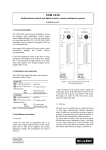
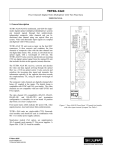
Figure 1. Front panel features of the CCM
1000 TX (left) and RX
CCM TX
o→ (optical connector)
o← 8xCC (37-pin conn.)
optical out
CC inputs, data out
Indicator LEDs
*DC
*FR
DC power good
signal framing OK
CCM RX
o← (optical connector)
o→ 8xCC (37-pin conn.)
optical in
- After switching on the system, check whether all
LEDs glow green. If the FR LED on the CCM TX
is red, that unit is faulty. If the SYNC LED on the
RX lights red while the FR LED glows green,
please check the optical link first.
CC outputs, data in
Indicator LEDs
*DC
DC power good
*SYNC
input signal sync OK
Table 1. CCM front panel features
3. Installation instructions
3.1 General
- Insert the units into an appropriate MC 11 or
similar power supply cabinet (and/or connect standalone units to their power supplies) and connect
appropriate cabling. Pin assignments are listed in
section 5.
3.2 Link type
The unit will try to establish and use a link type
based on link input measurements (default
autodetect mode; it will hold on to an interface as
long as signal is present). To permanently select
either the optical or the RS-232 link, internal dip
switches can be set.
To access these switches, take out the front panel
Phillips head screws indicated in figure 1 and slide
out the front panel/circuit board assembly. Dip
switches S1/S2 select between autodetect, the serial
link and the optical link (see figure 2 and table 2).
S2
OFF
OFF
ON
ON
S1
OFF
ON
OFF
ON
Dip switch
function
autodetect (default)
optical
RS-232
optical
2 1
Table 2. Dip switch settings for link type selection
ON
4. Care and maintenance
PC PANEL CCM
650 2197 0P1
WWJJJJ
(transmitter)
(receiver)
In order to maintain reliable operation of the
system, please observe the following precautions:
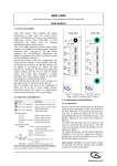
Figure 2. CCM TX/RX circuit board with dip switch.
for link type selection (see text).
- prevent dust from collecting on the equipment
- protect the equipment against moisture
- maintain sufficient free space around the equipment for cooling.
General safety and EMC information will be found
in the final section of this document.
37/ 19
CC 1 out B 37
5. Pin assignments of the 37-pin connector
A 18
CCM 1000 D-37 connector pin assignments are
listed in table 3 below, combined for TX and RX
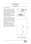
units; they are rendered graphically in figure 3.
Pin
no.
Assignment
Pin Assignment
no.
1
2
3
4
5
6
7
8
9
CC1 in
CC2 in
CC3 in
CC4 in
CC5 in
CC6 in
CC7 in
CC8 in
RS-232 out
(CCM TX)
GND
CC8 out A
CC7 out A
CC6 out A
CC5 out A
CC4 out A
CC3 out A
CC2 out A
CC1 out A
not used
20
21
22
23
24
25
26
27
28
10
11
12
13
14
15
16
17
18
19
29
30
31
32
33
34
35
36
37
CCM RX
(Pins 11-18 and
28-37)
CC 8 out AB
GND
GND
GND
GND
GND
GND
GND
GND
RS-232 in
(CCM RX)
GND
CC8 out B
CC7 out B
CC6 out B
CC5 out B
CC4 out B
CC3 out B
CC2 out B
CC1 out B
29
GND
28
RS-232 in
GND 10
CCM TX
(Pins 1-10 and 20-27)
RS-232 out 9
8 CC 8 in
27
GND
20
Table 3. D37 pin assignments of CCM 1000 TX (pins 1-9)
and RX (pins 11-37). GND pins are the same for both.
1 CC 1 in
Figure 3. CCM 1000 RX (top) and TX
(bottom) pin assignments. GND pins
indicated are on both units.
2
6. Technical specifications
7. Safety, EMC, ESD
The technical specifications of the CCM 1000
system are listed in table 4 below.
General
Feature
The safety information contained in this section, and on
other pages of this manual, must be observed whenever this
unit is operated, serviced, or repaired. Failure to comply with
any precaution, warning, or instruction noted in the manual
is in violation of the standards of design, manufacture, and
intended use of the unit.
Installation, adjustment, maintenance and repair of this
equipment are to be performed by trained personnel aware of
the hazards involved. For correct and safe use of the
equipment and in order to keep the equipment in a safe
condition, it is essential that both operating and servicing
personnel follow standard safety procedures in addition to the
safety precautions and warnings specified in this manual, and
that this unit be installed in locations accessible to trained
service personnel only.
Optelecom-NKF assumes no liability for the customer’s
failure to comply with any of these safety requirements.
Unit
Value
System I/O
Contact closure I/O
Number of channels
Input
Input sink (max)
Activation threshold
Output (potent.-free)
Output switch rating
System response time
Interface detect poll
Optical
Wavelength
Fibre type
TX output power
RX min. input power
System budget
8
+5 V pull-up, 10 kΩ
2.5
0.75 (<1.5 kΩ)
normally open, fail-safe
2 A @ 30 VDC (per switch)
<2
400
CCM 1010
mA
V
ms
ms
CCM 1050
850
multimode
(50/62.5)
-21
-45
≥ 28 (23)1)
1310
single-mode
-10
-45
≥ 35 dB
nm
UL/IEC/EN 60950-1: General safety requirements
dBm
dBm
The equipment described in this manual has been
designed and tested according to the UL/IEC/EN 60950-1
safety requirements.
If there is any doubt regarding the safety of the equipment, do
not put it into operation. This might be the case when the
equipment shows physical damage or is stressed beyond
tolerable limits (e.g. during storage and transportation).
Before opening the equipment, disconnect it from all power
sources. The equipment must be powered by a SELV*) power
supply.
When this unit is operated in extremely elevated temperature
conditions, it is possible for internal and external metal
surfaces to become extremely hot.
Electrical
Data link interface
Data rate
RS 232
20k
bit/s
Management
LED status indicators
*DC
(TX) *FR
(RX) *SYNC
power-on indication (green)
framing okay
input synchronised
Environmental and Safety
Operating temp. range
Relative humidity
Sinusoidal vibration
Drop and topple
Electrical safety
UL recognition file
Laser safety
EMC immunity
EMC emission
-40 to 74
<95 (no condensation)
IEC69-2-6, Test Fc: [email protected]/s2
IEC68-2-31, Test Ec
AL / IEC / EN 60950-1
E242498
IEC 60825-1, IEC 60825-2
EN 55024, EN 50130-4,
EN 61000-6-2
EN 55022 (Class B)
FCC 47 CFR 15 (Class B)
°C
%
+&-12 (±10%)
TX: 1.1 ; RX: 1.2
VDC
W
Optical safety
This optical equipment contains Class 1M lasers or LEDs
and has been designed and tested to meet IEC 608251:1993+A1+A2 and IEC 60825-2:2004 safety class 1M
requirements.
Optical equipment presents potential hazards to testing and
servicing personnel owing to high levels of optical radiation.
When using magnifying optical instruments, avoid looking
directly into the output of an operating transmitter or into the
end of a fibre connected to an operating transmitter, or there
will be a risk of permanent eye damage. Precautions should
be taken to prevent exposure to optical radiation when the
unit is removed from its enclosure or when the fiber is
disconnected from the unit. The optical radiation is invisible
to the eye.
Use of controls or adjustments or procedures other than
those specified herein may result in hazardous radiation
exposure.
The installer is responsible for ensuring that the label
depicted below (background: yellow; border and text: black)
is present in the restricted locations where this equipment is
installed.
Electrical
Supply voltages
Power consumption
Mechanical
Optical connector
I/O connector
Serial connector
Housing
ST
FC (others on request)
D37, female
2 (TX), 2 (RX) pins on D37
Eurocassette or SA
Table 4. CCM 1000 technical specifications
1)
Into 50/125μ fibre
Hazard Level 1M
The locations of all optical connections are listed in the
Indications and Connectors section of this manual.
Optical outputs and wavelengths are listed in the Technical
Specifications section of this manual.
3
EMC
The equipment has been tested and found to meet the CEregulations relating to EMC, and complies with the limits
for a Class B device, pursuant to Part 15 of the FCC rules.
These limits are designed to provide reasonable protection
against interference to radio communications in any
installation. The equipment generates, uses and can radiate
radio frequency energy; improper use or special
circumstances may cause interference to other equipment or a
performance decrease due to interference radiated by other
equipment. In such cases, the user will have to take
appropriate measures to reduce such interactions between this
and other equipment.
Any interruption of the shielding inside or outside the
equipment could cause the equipment to be more prone to fail
EMC requirements.
Non-video signal lines must use appropriate shielded CAT5
cabling (S-FTP), or at least an equivalent.
If system components, such as cabling (e.g. coaxial cable,
data/audio/cc wiring) and/or the units, are used outdoors,
ensure that all electrically connected components are
carefully earthed and protected against surges (high voltage
transients caused by switching or lightning).
ESD
Electrostatic discharge (ESD) can damage or destroy
electronic components. Proper precautions should be
taken against ESD when opening the equipment.
*)
SELV: conforming to IEC 60950-1, <60VDC output, output
voltage galvanically isolated from mains. All power supplies or
power supply cabinets available from Optelecom-NKF comply
with these SELV requirements.
©Optelecom-NKF 2006
Version 022106-2
CCM1000 (MW03SP-2)
4