1
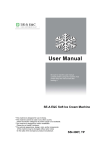
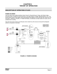
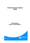
Compressed Air/Steam Piston Engine with Electronic Valve Control User’s Manual Thomas Gallmeyer S. Chad Gibbs 5/4/2010 Contents Introduction .................................................................................................................................................. 4 Specs list........................................................................................................................................................ 4 Operating range ........................................................................................................................................ 4 Input PSI ................................................................................................................................................ 4 Operating Speed ................................................................................................................................... 4 Safety considerations ............................................................................................................................ 4 Frame ........................................................................................................................................................ 5 80/20 design ......................................................................................................................................... 5 Cylinder ..................................................................................................................................................... 5 U bolts ................................................................................................................................................... 5 Cylinder Piece........................................................................................................................................ 5 Endcap................................................................................................................................................... 5 Spider .................................................................................................................................................... 5 Mounting Plate ..................................................................................................................................... 5 Piston System ............................................................................................................................................ 6 Piston .................................................................................................................................................... 6 PTFE/Buna Seal ..................................................................................................................................... 6 Bolt ........................................................................................................................................................ 6 Connecting Rods ....................................................................................................................................... 6 Piston rod .............................................................................................................................................. 6 Connecting rod ...................................................................................................................................... 6 Fork ....................................................................................................................................................... 6 Pin ......................................................................................................................................................... 6 Bushings ................................................................................................................................................ 6 Flywheel System ....................................................................................................................................... 6 Bearings................................................................................................................................................. 7 Shaft ...................................................................................................................................................... 7 Flywheel ................................................................................................................................................ 7 Drive Wheel........................................................................................................................................... 7 Position Sensing .................................................................................................................................... 7 DAQ System .............................................................................................................................................. 7 System Setup ................................................................................................................................................ 7 Mechanical Configuration ......................................................................................................................... 7 Initial flywheel position ......................................................................................................................... 8 Electrical configurations............................................................................................................................ 8 Power Strip............................................................................................................................................ 8 Labview VI Description.............................................................................................................................. 8 Access Data from USB DAQ card........................................................................................................... 8 Analyze Data ......................................................................................................................................... 9 Valve Control....................................................................................................................................... 11 Data Storage........................................................................................................................................ 12 Lessons Learned: VI ............................................................................................................................. 12 DAQ Setup ........................................................................................................................................... 13 Valve Wires: ........................................................................................................................................ 13 Power Source Wires ............................................................................................................................ 13 Pressure Sensor Wires ........................................................................................................................ 13 Inlet Relay Wiring ................................................................................................................................ 14 Outlet Relay Wiring ............................................................................................................................. 14 Operating Procedure................................................................................................................................... 14 Setup ....................................................................................................................................................... 14 Operation ................................................................................................................................................ 15 Safety ...................................................................................................................................................... 15 Lessons Learned .......................................................................................................................................... 15 Forward Directions...................................................................................................................................... 16 Attachments................................................................................................................................................ 16 Labview VI Files ....................................................................................................................................... 17 Solidworks Models .................................................................................................................................. 17 GWDD Presentation ................................................................................................................................ 17 Contact Info................................................................................................................................................. 17 Introduction This document provides background information for the compressed air/steam piston engine developed by Thomas Gallmeyer and S. Chad Gibbs as a senior special project design class for Duke University’s Pratt School of Engineering, Department of Mechanical Engineering and Materials Science, from September 2009 to May 2010. Included in this user manual is information on the components in the engine, design considerations for the engine, background on the control methodologies for the engine, operating instructions, qualitative lessons learned, and directions for future work. The goal of this project was to construct a lightweight electronically controlled steam engine to reevaluate potential applications of steam engine technology in transportation and energy production. The motivation was to understand if the application of modern materials and control mechanisms could make steam engines competitive with technologies such as the internal combustion engine. Further motivation comes from the ability to create steam from renewable sources (biomass, and solar) meaning a modern steam engine could be run renewably. Because of time and safety considerations the project direction was shifted towards creating a single stroke cylinder that could run on both steam and compressed air. Furthermore, the application of modern lightweight materials was superseded by the desire to create a robust test rig that will allow for the testing and optimization of electronic control mechanisms. The efforts of the project centered on the design and construction of the test rig and the testing and analysis of the test rig operated using compressed air, actuated by a pair of on-off solenoid valves with a Labview controller. Specs list Drawings and CAD models of all discussed parts are provided electronically. Operating range Input PSI The system was designed for operating using 60-70psi as available from the “shop air” supply, or the Hudson building air lines. Mechanically, the system is designed for up to 100psi with significant factors of safety. The safety release valve on the cylinder head will automatically exhaust pressure above 100 psi. The system should be capable of using steam as an input, but this was never tested. The introduction of a temperature gradient by hot steam and the resultant thermal expansion of the cylinder and piston could present fitment issues that could adversely affect engine performance. Additionally, hot steam would make an adiabatic stroke possible, significantly changing the optimum timing for the engine. Operating Speed The system was mechanically designed to operate at a speed below 1200 rpm. It was not anticipated that the system would surpass 400 rpm, given its size and the available input pressure. Most initial operation of the engine was below 100 rpm, generally between 50 and 70 rpm. Safety considerations Because of the considerable force that the piston is capable of, it is important to understand the behavior of the system before operating at high pressure. The system is capable of jamming itself at back dead center and building up pressure, resulting in a situation where a slight energy input can create a sudden acceleration of the piston and flywheel, potentially causing serious injury. Frame 80/20 design The frame was constructed out of 80/20 extruded Aluminum, providing easy mounting for configuration modification. The frame provides a solid static support for the apparatus; however, it was observed that the middle longitudinal 80/20 bar bends during the application of torque to the flywheel, changing system geometry and potentially exacerbating timing issues and creating a misalignment in components, increasing friction forces. Cylinder U bolts U bolts are used to hold the cylinder in place on the mounting plate. It is important that they are tightened down together (gradually tightening each of the four nuts) so that the cylinder remains properly aligned with the frame. Cylinder Piece The cylinder is machined from a bronze pipe. The material selection for the cylinder was driven by the desire for the system to be self lubricated. Traditional steam engines which used cast iron for the cylinders and had pistons which were sealed with metallic rings required the entering steam to be injected with oil or other lubricant. This process often made the outlet steam unusable. To avoid this traditional method for lubrication the cylinder was constructed using non-traditional materials. The cylinder was machined out of bronze, a material commonly used for bearings. This material provided a slick surface for a PTFE piston ring to slide on, even in the presence of the significant radial force which was required to maintain a pressure seal. More discussion of the success of this design will occur during the system characterization section. The factor of safety for the cylinder was calculated using a Solidworks FEA analysis with pressure above the nominal operation range. The initial design had more material taken off the cylinder to minimize weight, but this wasn’t realized to minimize construction time and cost. Endcap The aluminum endcap is sealed to the cylinder with a cork-rubber composite gasket seal material. It is held in place by ten ¼”-20 bolts that are threaded into the bronze cylinder piece. The ¾” aluminum also houses four threaded holes for the 3/8” NPT (5/8” hole) inlet and exhaust valves, 3/8” NPT (5/8” hole) pop-off valve, and the 3/8” Spider The spider plate holds a ¾” ID bronze linear bearing. The holes in the circular plate allow air to escape when the cylinder moves. This piece keeps the piston rod true to the center of the cylinder and provides radial support for reaction forces in the y-direction (facing the side of the flywheel) when the drive wheel isn’t at top or bottom dead center. Mounting Plate The cylinder is mounted on an aluminum plate. This plate is fairly simple and has holes drilled for both the through u-bolts and mounting to the 80/20. Not much to see here. Piston System Piston The piston is a compound part consisting of a large through-bolt, two aluminum pieces, and a seal consisting of a compressible Buna-N o-ring and outer PTFE seal. The aluminum pieces sandwich the seal and are held in compression by the through bolt, which is threaded to the piston rod. PTFE/Buna Seal The inner rubber o-ring absorbs impact energy and provides outer compressive forces to ensure an effective seal during dynamic loading on the piston. The outer PTFE seal is constantly in contact with the outer bronze cylinder, providing a slippery and wear-resistant seal for the piston’s action. Bolt The bolt serves as the connection between the piston and the piston rod. The piston rod is threaded and tightens down on the piston pieces, securing them together through compression and holding the seal in place. Connecting Rods Piston rod The piston rod is a precision ground ¾” OD hollow steel shaft. It is threaded on both ends and transfers force through compression on the power stroke and the return stroke. It is attached to bolts on both ends. Connecting rod The connecting rod is a square hollow aluminum tube. It transfers force through compression from the piston rod to the drive wheel on the flywheel setup. It is mounted with two bronze bushings on the flywheel side for the pin connected to the drive wheel. Fork The connecting rod fork is machined from aluminum and provides a pivot to transfer the rotational motion of the flywheel to linear motion in the piston/cylinder. The fork uses two bronze bushings on a steel pin in the connecting rod for this pivot, and is counterbored for the head of a bolt to connect to the piston rod. Pin A ¼” steel pin is used to transfer power between the two rods in the fork. Bushings ¼” bronze bushings are used for the pivot on the steel pin. Flywheel System Bearings The flywheel uses two 1” ID mounted bronze bushings for rotational motion. These bushings are elevated to the center of the cylinder using 1 ½” aluminum blocks. The bearings support large radial loads from the power stroke and return stroke and also support the weight of the flywheel setup. Shaft The flywheel uses a 1” precision shaft. 1” is larger than is mechanically necessary, but the size was chosen to make the machining of the flywheel easier. Flywheel The flywheel is a 12” diameter and 1” thick cast iron disc. It is held in place by a key and the shaft is notched for this key, locking the flywheel in place and ensuring that it does not rotate on the shaft. Aluminum collars hold the flywheel in place to keep it from moving axially. Drive Wheel The drive wheel is a 6” diameter and 1” thick steel disc. It is held in place similarly to the flywheel, except one end does not have an aluminum collar to allow for free rotation and clearance of the connecting rod. This design may need to be amended in the future as the drive wheel can freely work itself off of the shaft, creating alignment issues. This has not been a significant problem at low operating speeds. Position Sensing An inductance probe on the flywheel provides position feedback to LabView. The inductance probe gives a linear relationship between position and voltage for any given material. However, for different materials with different conductivities the scaling coefficients do not remain the same. After some initial testing it was determined that a strip of aluminum tape on the cast iron fly wheel was seen as a 6-8V drop in signal from the inductance sensor. This was a large enough change to consistently be recorded by the DAQ system and act as a trigger. DAQ System The system uses a NI USB DAQ card to acquire position and pressure data and sends signals for inlet and exhaust valve actuation. The DAQ card is controlled using LabView 9. The control system will be discussed in detail in subsequent sections. System Setup Mechanical Configuration In general, the system works as the inlet pressure pushes on the piston head, forcing it towards the flywheel. When this force is applied when the wheel is not perfectly at back dead center, this force is applied at a moment arm on the drive wheel. This creates a torque, turning the flywheel setup. This power stroke can occur between 0 and 180 degrees of clockwise rotation, with the applied force (connection between connecting rod and drive wheel pin) starting at 3 o’clock when viewing the drive wheel from its outward face. The flywheel setup is accelerated, increasing the angular momentum of the system. In order to be self-sustainable, this angular momentum must be enough to return the flywheel back to back dead center. This exhaust stroke robs the system of angular momentum because some of this energy is used to overcome friction and most of it is used to push air out of the cylinder through the exhaust valve. Minimizing the energy required to exhaust this air is crucial to the efficient operation of the engine. Initial flywheel position As currently coded, the software is set up for clockwise rotation. This is a result of how the position encoding is set up, as the reset can be set to either the beginning or the end of the inductance spike caused by the passing razor blade. Electrical configurations Power Strip A power strip is used to power the valves through a 24 volt AC to DC transformer. Because of how the relays for the valves are wired, when 24V is supplied, the exhaust valve stays on and the inlet valve stays off. This means that current is always flowing through the exhaust solenoid when the power strip is on. The valve heats up when constant current is applied, so it is important to keep the power strip switch in the “off” position when not operating the device. Conversely, it is necessary to turn the strip to “on” if the user desires to manually move the position of the piston/flywheel setup, because the exhaust valve must be open in order for air to move into and out of the cylinder. Labview VI Description Figure 1: Control System 4.0 with Position Save VI This portion of the user’s guide gives a quick overview of the VI that is part of the attached documents and is named “Control System 4.0 with Position Save.” The purpose of this section is to describe the VI to a level that will allow a user to make medications and understand what the inputs and the outputs to the system will accomplish. In order to do this I will go through the 4 different sections of the VI which are all shown above in Figure 1: Control System 4.0 with Position Save VI. The 4 aspects that are controlled or done by this VI is 1) Access data from USB DAQ card, 2) Analyze data to determine position and pressure, 3) Use position data to control valves and 4) Save data to file. Access Data from USB DAQ card Figure 2: Data Acquisition VI Figure 2: Data Acquisition VI shows the portions of the VI that are used to read the data. The DAQ Assistant block is used to access signals from the DAQ card. The settings for the DAQ assistant are currently set to read data from the NI USB 6009. If a different DAQ card is used the user must double click on the block to bring up the DAQ assistant dialog. The dialog allows you to choose which USB signals that you want to access. In order for the VI to work navigate to the analog channels that are being used to record pressure and position (Analog Input 0 and Analog Input 1 currently). Because we wanted to directly use the VI for control we wanted real time data so we selected the program to give us 1 data point on demand. In the future if this program is only used for data logging and not control better resolution on the data can be achieved by asking for 1000’s of datapoints at a time by changing the timing to N Samples @ a given rate and a number of samples that is wanted by the user. The next two blocks are responsible for splitting the signal so the position data and pressure data can be accessed individual. Depending on the order of the signals in the DAQ assistant block the two “Select Signal” blocks should be modified to ensure that the output of the top block is the analog pressure signal and the output of the bottom block is the analog position data Analyze Data The pressure data analysis was as simple as applying a calibration curve to the data. The calibration method for the 100 PSI gauge transducer that was used, was to subtract .5 V from the signal and then multiply the result by 25 to get the gauge pressure in Psi. This is done in Labview by using a multiplication and addition blocks. The second portion of the data analysis was to determine position from the readings from the proximity sensor. In the future this aspect will probably be changes by using a potentiometer that supplies a voltage directly proportional to position. Based on a max operating speed of 120 RPM (4 rad/sec) Equation 12 suggests that the DAQ only collects a sample every 8.6 degrees from the proximity. ( ) With this data it was not surprising that there were instances when the trigger was not seen by the sensor with only 10 degree spacing. In order to remedy the situation the size of each aluminum tape was widened to 20 degrees with 20 degree spacing. Because of this, In order to get 4 data points around each center it became necessary to have triggers throughout the entire rotation of the flywheel as shown in . With this setup it became necessary to have a hard reset once per revolution to ensure that the divergence from absolute position was not lost if a signal was missed. This was done using a razor blade which provided a 4V jump in the signal. This method proved a good way to provide position and velocity data. Velocity was determined from the signal by dividing 40o by the time between triggers. The current distance from the last trigger was then calculated to be the time since the last trigger multiplied by rate from the previous two triggers. In order to do this in Labview it is important to be able to count the rises and falls of the of the signal. This was accomplished by using a “trigger and gate” block in Labview. The settings in this block are set to output a single data point every time the signal rises or falls below a given level. By double clicking on the block the level of the trigger can be changed based on an analysis of the output data. The top loop looks at the fall caused by the aluminum tape. This signal has an if statement that records the time and increments a index every time a trigger is recorded. The if statement also updates the velocity based on the time between the current time and the previous trigger. In the diagram the outputs from the loop are 1 (red line) the time of the last trigger, 2(top orange line) velocity and 3 (bottom orange line) index of the trigger. When the trigger and gate is not triggered this data is simply passed through. A tricky aspect of coding this section was learning how to pass data through iterations. This is done with the downward facing arrows in the code. These arrows can be created by right clicking on the walls of the loop and adding a “Shift register.” The second trigger and gate loop is looking for a rise in signal that is caused by the razor blade. This signal causes the index to reset. Figure 3: Position Analysis Valve Control Figure 4: Valve Control Currently valve control is a function of position. The sliders on the front panel of the VI are used to control the limit values for the valve opening and closing. The block this diagram for this operation is easy to explain because it simply compares the predicted position derived by the previous block diagram and sees whether the valve should be open. The exhaust valve is actually turned off by a number between -20 and 10 because the reset occurs at a position of -20 so in the places when the exhaust should fire the current position sensor predicts that the position is – or slightly positive. The intricacies of this portion of the control is the not block between the output of the exhaust compare block. This difference arises from the difference in the way that the inlet and exhaust valves are wired. The exhaust valve is wired in a way that the valve is normally open you send a signal to cut off voltage to the valve, causing it to close. This was done to allow the system to exhaust even when no control signal is attached for emergency operation. Another feature that is an important aid for debugging is the 5 multiplying the signal that is sent to the DAQ assistant. The way that the system is currently wired, changing this value to 0 will allow the exhaust valve to stay open while the inlet remains useful. For the current position sensing this was a valuable tool in collecting trigger data for calibration. The DAQ assistant is coded much the same way as the input assistant was configured using the GUI. This time the analog outputs are specified (AO1 and AO2) which trigger the relays. Data Storage An important step for analysis of the operation of the system is writing the data to a file. This process is accomplished using the “Write to Measurement File” block that is shown in Figure 5: Data Storage. Understanding this block can be broken into two steps. First using the current configuration creates a file that can be opened using excel. The data in each of the columns is ordered in the order of the inputs to the combine signals block. For the current VI, the odd columns are timestamps for when the data is collected. The 2nd column contains the pressure reading (in psi). The 4th column gives the proximity sensor valve after being modified by a voltage add. Column 6 stores the predicted position in degrees, column 8 stores the signal to the outlet relay and column 10 stores the signal to the inlet valve. The operation of this block to store more or less can be modified by adding or subtracting from the combine signals block. Another important change that must be done to operate the VI is to double click on the block and change the location of the data storage. This will have to be changed every time the VI is run on a different computer. If you do not do this the block will blink when you try and run it. Figure 5: Data Storage Lessons Learned: VI 1)If the Write to Measurement File block flashes when attempting to run the program it is likely because the program is likely trying to write to a folder that doesn’t exist 2) If the DAQ assistant block flashes 1. Check to make sure the USB cord is plugged in 2. Double check that the input channels in the DAQ assistant block are for the correct DAQ card (esp when switching to a different DAQ card_ 3. May not be grounded correctly causing the program to fail 3) The offset and trigger values for position sensing were determined by looking of a plot of the data collected with the outlet valve open and seeing what values will cause the downward trigger for increment and positive trigger for reset 4) Setting Constant attached to output signal to 0 can be used to keep exhaust valve open for position diagnosis described above 5) When not running VI make sure to unplug USB and shut off power to the valves DAQ Setup GND (1) AI0 (2) AI4 (3) GND (4) AI1 (5) AI5 (6) GND (7) GND (13) AO0 (14) AO1 (15) GND (16) GND (32) +5V (31) To Pressure Transducer Ground (black) To Pressure Transducer Signal (white) To Pressure Transducer Ground (black) To non-powered common ground To Inductance Probe Signal To Inductance Probe Common To non-powered common ground To relay lead 2 (Inlet) To relay lead 9 (Inlet) To relay lead 9 (Exhaust) To relay lead 2 (Exhaust) To Pressure Transducer Ground (black) To Pressure Transducer Power (red) Table 1: DAQ Setup Details Valve Wires: Voltage difference is 24 V to activate and 20W Black: Ground Red: Positive Yellow: Negative (This should be connected directly to the Green Wire (Negative) from Power Source) Power Source Wires Voltage difference is 24 V and 18 W Green: Negative Purple: Positive Pressure Sensor Wires Black: Ground Red: 5V power supply White: Signal (0-5V) Inlet Relay Wiring The system used an Omron G5V relay to use the 5V low current signal from the USB DAQ card to control the 24VDC 20 watt signal to the valve. From DAQ AO0 (Not Ground) Positive Power from Power Source To Solenoid Positive (Red) From DAQ AO0 (Ground) Outlet Relay Wiring From DAQ AO1 (Not Ground) Positive Power from Power Source To Solenoid Positive (Red) From DAQ AO1 (Ground) Operating Procedure Setup It is important to ensure that the mechanical system is properly aligned before operation. There is currently no quantitative method of ensuring proper alignment: the best practice is to ensure that the flywheel is properly and firmly seated within its (it shouldn’t wobble), the drive wheel is flush with the end of the 1” shaft, and the two ¼” pins and their bushings are aligned such that binding isn’t an issue. Finally, the connecting rod should be parallel to the face of the drive wheel and parallel to the piston rod and the cylinder and frame. After alignment, ensure that the power switch for the encoder power supply is turned on (watch for the green LED). Ensure that pressure is available by opening pressure supply valves (current optimal pressure range is 25-35 psi). Boot up Labview, load up “Control System 4.0 With Position Save.vi”, move the flywheel to just counter-clockwise of back dead center, switch on the power to the 24V transformer with the switch on the power strip, and start the LabView VI. There may be an error originating in the “Write To Measurement Block”, which saves operation data. The file directory will be invalid, so this must be changed in the block properties before continuing. Minding the fact that upon tripping whatever valve timing is set up the inlet will suddenly apply pressure to the piston and accelerate the flywheel, manually move the flywheel clockwise so the piston move past back dead center to start operation. Operation Once operating, the valve timing can be adjusted using the sliders on the front panel for the VI. The system is currently set up to save pressure, encoder triggers, predicted rotational position, inlet and exhaust signal on a time basis to a specified location in the “Write To Measurement File” block. Safety Be mindful of the fact that the system can sometimes behave erratically and with significant force. Keep hands, hair, clothing, etc away from the flywheel and all moving parts. Avoid standing in the plane of rotation at high speed or when trying high pressures or unknown timing maps (after all, there is a razor blade turning on a wheel with a half foot radius… remember this, and consider implementing a more permanent solution for encoder reset triggering). Lessons Learned 1) Grounding! a) DAQ must be very well grounded for operation i) Without effective ground, voltage building trips circuit breaker in DAQ, aborting session ii) Can be reset by unplugging and replugging USB from DAQ b) Failure to sufficiently ground DAQ will cause system to prematurely shut down during operation c) Good practice to have separate grounds for powered and DAQ systems 2) Peak of 5 Psi on exhaust stroke is a cause for concern a) 5 psi = 25lbf working towards stopping the flywheel. i) Because in the middle of the return stroke this is applied at 2.5 inch radius (Lots of torque) b) A more efficient or better flowing exhaust valve is a logical next step 3) Regularity of the pressure data suggests position can be determined by transducer reading a) Ability to double check position data and add resolution i) Application of ANN to learn pressure profile to cylinder position b) Use just the transducer for timing. 4) Velocity slows significantly when attempting to return to back dead center a) Develop a 2 piston apparatus that is able to have two power strokes per cycle b) Extracting energy can only be done during the power stroke because too much resistance will stop cylinder. i) More resistance on power stroke will be a better use of supplied pressure 5) Complexity of position encoding leaves much to be desired a) System currently requires frequent calibration of trigger voltage levels b) 360 degree potentiometer may provide better solution c) Traditional rotational encoder is an option 6) DAQ/LabView performance is limited by computer performance a) Even though DAQ card is capable of many thousands of samples per second, it currently must talk to the computer after each sample, limiting it to ~2-3 ms between samples, or only around 50 Hz. System performs best when no programs are open aside from LabView, and LabView is set as priority process is task manager b) A hybrid system using the DAQ/LabView to receive performance data (maybe every few seconds instead of every few milliseconds in order to increase performance) and send timing data as constant voltages along with a programmed microchip capable of executing valve opening/closing based on preset valve timing data as supplied by the DAQ. Forward Directions The work conducted for this project creates a foundation for future testing of electronically actuated pneumatic and steam piston control at Duke. The test rig and instrumentation that were developed were intentionally created in a manner that allows substitution and replacement. While there is a wide range of further research that will be able to use the test rig there are a number of avenues that could produce extremely valuable insights. The first avenue is developing an understanding of the different optimized timing configurations for different operating conditions for the cylinder such as speed and inlet pressure. Similarly the mathematical model developed though the system characterization testing can be used to design optimal or intelligent controllers. Secondly the rig could be deployed to rapidly test proposed cam designs without machining a part. By developing a model of the cam in Labview the performance could be simulated electronically. Finally the system could incorporate solenoid valves that have accurate position feedback which could allow for the exploration of different inlet and exhaust opening and closing profiles and the respective impact on performance. In conclusion, the efforts on the project lead to the creation of an apparatus for evaluating electronic valve operation for a steam/compressed air system. While we were not able to directly evaluate whether a modern steam engine could be used for power generation and transportation good progress was made towards developing a manner to test and evaluate vital technologies for a modern steam/compressed air system. The project was a combination of mechanical design and system testing and analysis. Summary: 1) Improve exhaust characteristics a) Valve with higher flow characteristics or the b) Inclusion of more valves 2) Design intelligent or optimum controller using the mathematical model and system characterization results 3) Explore the performance improvements gained by applying variable valve timing based upon operating conditions a) Torque required b) RPM c) Inlet pressure 4) Install solenoid valves with position feedback to explore affects of varying valve profiles Attachments Labview VI Files Labview VI file for operation is attached Solidworks Models All available solidworks models are attached, some dimensions may be slightly different after machining so be sure to double check with the physical apparatus if referencing solidworks model. GWDD Presentation Copy of presentation given for Graduation with Departmental Distinction Contact Info Thomas Gallmeyer: [email protected] S. Chad Gibbs: [email protected]