1
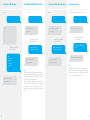
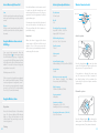
Home Mode
Press the Home Mode button { } on the
remote control. The system state LED is on. All
the sensors in regular zones are armed except
those in the Home Mode zone. The sensors in
the Home Mode zone are disarmed so that
users can move inside their home.
Mute Mode
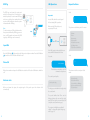
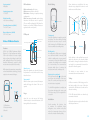
Zone Setup of Wireless Accessories
Wireless Door / Window Contact
Every detector can be assigned to 4
different categories of zones: Home Mode
Zone, Single Delay Zone, Normal Zone
and 24-H Zone. To assign a detector to a
zone, open its case and move its jumpers
according to the drawing below:
Features
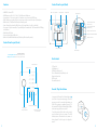
The ES-D3A is a Door / Window Contact that
can be installed on doors, windows, and
any other objects that open and close. The
sensor sends signals to the control panel
when the magnet installed next to the
sensor is deconnected.
Thanks to the tamper switch, any attenpt
to move the Door / Window Contact will
trigger the alarm.
D0
D0
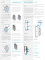
Installation
- Open the case and remove the battery
activation strip.
- Mount the sensor on the door and the magnet
on the door frame.
- Make sure the magnet is placed above of the
transmitter.
- Mount the magnet max. 1cm away from the
transmitter and secure the transmitter and
magnet with double-sided tape or screws.
- Avoid mounting the sensor in areas with a
large amount of metal or electrical wiring, such
as a furnace or utility room.
D3
D3
A. Home Mode Zone
Magnet
B. Single Delay Zone
Transmitter
D0
Press the Stay button { } on the remote
control. Press the Arm button { } or the
Disarm button { }. When arming or disarming
the system, the siren does not ring out: the
system is armed or disarmed in Mute Mode.
LED indicator
C. Normal Zone
D3
The PIR motion detector is set in Home
Mode Zone by default. It is recommended
to set the Door / Window Contact at the
entrance of your home in Single Delay Zone.
After a zone has been changed, the detector
must be registered in the control panel again.
LED indications
Blinks once: the door or window is open
and the transmitter sends a signal to the
control panel.
Blinks quickly: Low power indication: the
batteries must be replaced.
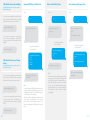
Emergency Mode
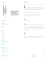
Specifications
Power supply
DC 12V (A23 12V Battery x 1)
PCB Layout
Static current
≤ 30 uA
D0
Tamper switch
D3
16
Regardless the status of the system, the alarm
is triggered when the Panic button {SOS} is
pressed on the remote control.
24-H Zone
Note
It is recommended to set the smoke
detector, the gas detector and the outdoor
beam sensor at 24-H zone.
A23 12V Battery
Zone setting
Alarm current
≤ 40 mA
Transmitting distance
≤80 m (in open area)
LED working indicator
Radio frequency
315 MHz / 433 MHz (±75 KHz)
17