1
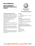
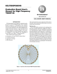
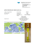
Note: This document is designed to meet the requirements for documentation to be
shipped with a product for products shipped to the European Union and other
countries.
It does not replace the “9601 SBD Transceiver Developers Guide.”Developers
should only rely on the Developers Guide for detailed technical information.
9 6 0 1 S h o r t B u r s t D a t a O n l y Tr a ns cei ver
Us e r ’ s G ui d e
Iridium Satellite LLC
6701 Democracy Blvd., Suite 500
Bethesda, MD 20817 USA
Toll Free: +1.866.947.4348 [US Only]
International +1.480.752.5155
Fax +1.480.752.1105
Unit 11email:
– 33 Riley
Road – Woodmead
[email protected]
+ 27 11 612
3660
[email protected]
web:www.iridium.com
www.gc-sat.com
Contents
1.0
Product Overview ............................................................................................................... 3
2.0
Standards Compliance ........................................................................................................ 3
2.1
FCC Compliance............................................................................................................. 3
2.2
CE Compliance ............................................................................................................... 4
2.3
Canadian Compliance ..................................................................................................... 4
3.0
Physical Specifications ....................................................................................................... 4
3.1
Dimensions ..................................................................................................................... 4
3.2
Mechanical Dimensions – Mounting .............................................................................. 5
3.2.1
Mounting - Stackable Design.................................................................................. 5
3.2.2
Mounting to a Panel/Surface – For use with cable connections ............................. 8
4.0
Environmental..................................................................................................................... 9
4.1
Interface Connectors ..................................................................................................... 10
5.0
Electrical Interfaces .......................................................................................................... 10
5.1
Multi-Interface Connector ............................................................................................ 10
5.1.1
Connector Type..................................................................................................... 10
5.1.2
Connector Pin Allocation...................................................................................... 11
5.2
DC Power Interface....................................................................................................... 12
5.2.1
Power On/Off Control........................................................................................... 13
5.3
Serial Data Interface ..................................................................................................... 13
5.3.1
9-Wire and 3-Wire Operation ............................................................................... 13
5.3.2
Configuration Settings .......................................................................................... 15
5.3.3
Modes of Operation .............................................................................................. 15
5.4
Hardware Failure Reporting ......................................................................................... 15
5.5
Network Available Output............................................................................................ 16
5.6
DC Power Output.......................................................................................................... 16
6.0
RF Interface ...................................................................................................................... 16
6.1
Antenna Connector ....................................................................................................... 16
6.1.1
Antenna Connector Type ...................................................................................... 16
6.2
R F Interface Specifications .................................................................................. 16
6.3
Radio Characteristics ............................................................................................... 17
7.0
Instructions for the safe Installation and use of the 9601 ................................................. 17
7.1
Instructions for t h e Integrator ................................................................................. 17
7.2
Instructions from the integrator to the user................................................................... 18
8.0
Modem Commands and Configuration............................................................................. 18
9.0
Export Compliance Information ....................................................................................... 18
10.0 Contacting Iridium Satellite LLC ..................................................................................... 18
1.0 Product Overview
The Iridium 9601 is a single board transceiver and is essentially provided as a ‘black box’ transceiver with
all device interfaces provided by a single multi-pin interface connector in addition to the antenna
connector. The product only provides the core transceiver. All other end user application functions such
as GPS, microprocessor based logic control, digital and analog inputs, digital and analog outputs power
supply and antenna must be provided by the solution developer. The device interface consists of the
serial interface, power input, network available output and power on/off control line.
The Iridium 9601 Short Burst Data Only Transceiver (9601) is designed to be integrated into a wireless
data application with other hardware and software to produce a full solution designed for a specific
application or vertical market. Examples of these solutions include tracking a maritime vessel or automatic
vehicle location. The 9601 only supports Iridium’s Short Burst Data (SBD) capability. It does not
support voice, circuit switched data, or short message service (SMS). This is a new product and
has no functional predecessor.
The 9601 meets specific regulatory requirements for FCC, Canada, and CE assuming an antenna with a
gain of ~3 dBi. This allows the 9601 to be integrated into a variety of wireless data applications or
retrofitted into existing SBD only applications that utilize SBD with the Iridium 9601 or 9522 L-Band
Transceiver-based products. Such finished products, when integrated together, require regulatory testing
to be conducted by the integrator.
The 9601 does not incorporate nor require a Subscriber Identity Module (also know as a SIM Card) to be
inserted into the transceiver.
1.1 Key Features
Single board transceiver
Small form factor
No SIM card
Designed to be incorporated into an OEM solution
Maximum mobile originated message size 205 bytes
Maximum mobile terminated message size 135 bytes
Uses small omni-directional antenna
Global operating capability
FCC, Industry Canada, CE certified
2.0 Standards Compliance
The 9601 is designed to comply with the standards for Radio Emissions Compliance, Electromagnetic
Compatibility, and AC Safety in the United States, European Union and Canada.
2.1
FCC Compliance
The 9601 is certified under 47 CFR Part 25 as FCC ID:Q639601. It also complies with Part 15 of the FCC
Regulations. Operation is subject to the condition that this device does not cause harmful interference. Any
changes or modifications, including the use of a non-standard antenna, not expressly approved by the
party responsible for compliance could void the user'
s authority to operate the equipment.
IMPORTANT: To comply with FCC RF exposure requirements, a minimum separation of 20 cm is
required between the antenna and all persons.
2.2
CE Compliance
This product, when marked with the CE symbol, complies with the European Community Council Directive
for R&TTE, 99/5/EC, provided that the integrator/user adheres to the instructions detailed in this Interface
Specification. This product is in compliance with applicable ETSI standards. Compliance with the
requirements of ETSI EN 301 489 requires the use of a shielded digital data interface cable.
2.3
Canadian Compliance
The 9601 is certified under RSS-170 of the Canadian Radio standards as IC: 4629A 9601. Operation is
subject to the condition that this device does not cause harmful interference. Any changes or modifications,
including the use of a non-standard antenna, not expressly approved by the party responsible for
compliance could void the user'
s authority to operate the equipment.
3.0 Physical Specifications
For illustrative purposes a rendering of the 9601 ISU is shown in Figure 1 with a ribbon cable connector
inserted. (Note that 9601 this ribbon cable connector is to be provided by the developer and is not
supplied as part of the product.)
Figure 1: The 9601 SBD Transceiver.
3.1
Dimensions
The overall dimensions of the 9601 and its weight are summarized in Table 2 and represented graphically
in Figure 2.
Table 2: 9601 Mechanical Dimensions
Parameter
Length
Width
Depth
Weight (approximate)
Value
106 mm
56.2 mm
13 mm
117g
Note that these dimensions are for the enclosure and do not take into account the connectors or mounting
hardware. Additionally developers should plan for additional space for the reciprocal connectors for the
antenna and user connector.
Figure 2 Dimensions of the 9601 SBD Transceiver.
Notes:
• The SMA Antenna connector is 10mm long
• The Samtec user connector rises 6 mm above the enclosure
3.2
Mechanical Dimensions – Mounting
The 9601 SBD Transceiver is provided with four mounting holes, one at each corner. During
manufacture four screws are inserted for shipping purposes. These screws need to be removed
for mounting. There are two basic options for mounting – stackable and mounting to a surface
such as a mounting plate or enclosure wall. The following sections provide further information.
3.2.1 Mounting - Stackable Design
An example stackable design is shown in Figure 3.
Figure 3: 9601 SBD Transceiver mounted to a unpopulated PCB.
The figures below provides mechanical information design information for a suitable ‘stackable’ 9601 to
developer PCB configuration
Figure 4: Assembly Item Number Identification. Item Numbers in Figure 4 are described in Table 3.
Not to scale. Dimensions in millimeters.
Table 3: Item Number Description for Figure 4
Item
1
2
3
4
5
Type
Assembly
Part
Part
Part
Part
6
Assembly
Description
9601 SBD Transceiver
M3 Shake-proof washer, zinc plated steel [4 supplied with item 1]
M3 x 20 Pan head screw, pozidrive, zinc plated steel [4 supplied with item 1]
M3 Threaded standoff, 6.0 A/F HEX x 12.00 mm
M3 x 8 Pan head screw, pozidrive, zinc plated steel
Solution developer PCB fitted with Samtec connector ESQT-113-02-L-D-425.
[This item is the same item as Item 1 in Figure 5.]
Quantity
1
8
4
4
4
1
Figure 5: Mechanical mounting foot print for use when stacking the 9601 ISU with a developer provided
PCB. (Dimensions in milli-meters, not to scale)
Notes for Figure 5:
1. Item 1 is a generic, developer provided PCB design and shown for illustrative purposes. This item is
the same as Item 6 in Figure 4.
2. Item 2 is available from Samtec in a variety of heights. This example shows a 0.425" version. The
part number for this connector is ESQT-113-02-L-D-425
3. Compatible heights of stand-offs and variants on Item 2 are as follows:
a. 0.425" height (shown) fits with 12mm high spacers
b. 0.327" height is minimum that can be used. Fits with 9.50mm spacers.
c. 0.800" height is the maximum height available fits with 21.50mm spacers.
d. Anything else in-between should work if '
Samtec height'= '
Spacer height'minus 1.20mm.
4. Suggested examples of spacer types and compatible fasteners:
a. M3 threaded thru'hole 6.0 A/F Hex x 12mm, re-use M3 x 20 shipping screws and
washers, add M3 x 8 screws and washers.
b. Plain thru'hole diameter 3.2-3.5, diameter 6.0 x 9.50mm, replace M3 x 20 shipping
screws with M3 x 30 screws (same nuts and washers.)
c. Plain thru'hole diameter 3.2-3.5, diameter 6.0 x 21.50mm, replace M3 x 20 shipping
screws with M3 x 35 screws (same nuts and washers.)
3.2.2 Mounting to a Panel/Surface – For use with cable connections
An example of mounting to a panel or other surface design is shown in Figure 6.
Figure 6: 9601 SBD Transceiver mounted to a plate or surface.
The figures and tables below provide mechanical information design information for a mounting a 9601 to
a plate or surface configuration
Figure 7: Assembly Item Number Identification.
Item Numbers in Figure 7 are described in Table 4. (Not to scale. Dimensions in millimeters.)
Notes for Figure 7:
1. Item 1 includes 4 off M3 x 20 shipping screws, shake-proof washers and nuts
2. Shipping screws can be used to attach Transceiver to panel of 2.00 mm maximum thickness
3. Panels thicker than 2.00mm require longer screws to be e.g. M3 x 25mm
4. See Figure 8 for mounting hole dimensions
Table 4: Item Number Description for Figure 7
Item
1
2
Type
Assembly
Part
Description
9601 SBD Transceiver
Mounting Plate or Surface (developer provided)
Figure 8: Mechanical mounting foot print for use when panel mounting 9601.
(Dimensions in milli-meters, not to scale)
4.0 Environmental
The environmental specifications of the 9601 are summarized in Table 5 below.
Table 5: Environmental Specifications
Parameter
Operating Temperature Range
Operating Humidity Range
Storage Temperature Range
Storage Humidity Range
The 9601 has been tested to the specifications listed in Table 6.
Value
-30ºC to + 60ºC
75% RH
-40ºC to + 85ºC
93% RH
Quantity
1
1
Table 6: Environmental Tests
Test Name
Test Reference
Thermal Shock
EN60068-2-14:2000
Humidity
IEC60068-2-3:1969
Shock
EN60068-2-27:1993
(NF c20-727)
J1455 Society of Automotive Engineers
Vibration
EN 60068-2-36:1996
Vibration
IEC 60068-2-36:1996
Vibration
J1455 Society of Automotive Engineers
Shock
4.1
Test Description
Change of Temperature,
-25C to +70C,
5 cycles of 1 hour each
Damp heat steady state
40C 93% RH for 4 days
Sinusoidal Vibration
0.96 m2/s3 from 5Hz to 20Hz
Sinusoidal Vibration
21Hz to 500Hz
-3dB per octave
Interface Connectors
The 9601 SBD Transceiver incorporates two connectors:
•
•
A multi-interface connector
An antenna connector
These interfaces are described in more detail in Sections 5 and 6 respectively.
5.0 Electrical Interfaces
The subsections to follow contain information for the electrical interfaces of the 9601 SBD Transceiver.
5.1
Multi-Interface Connector
The multi-interface connector includes six interfaces:
•
•
•
•
DC power supply input
Power on/off control
RS-232 Serial data
Network available output
5.1.1 Connector Type
The connector on the 9601 is a Samtec EHT series. This connector provides the ability for both a cable
connector as well as a stackable board to board connection. For cable connected applications use the
Samtec TCSD series. For PCB stacking use the Samtec ESQT series.
Data sheets on these connectors can be found at:
EHT Series: http://www.samtec.com/technical_specifications/overview.asp?series=EHT
TCSD Series: http://www.samtec.com/technical_specifications/overview.asp?series=tcsd
ESQT Series: http://www.samtec.com/technical_specifications/overview.asp?series=esqt
5.1.2 Connector Pin Allocation
The user connector is a 2 row 26-way latching header. Individual pin assignments are shown in Table 7.
Multiple supply grounds are provided and all supply and supply grounds (pins 1-6) are required to be
connected to the power supply in order to limit the current on any one pin. The three Supply Returns (pins
4, 5 & 6) are tied together at the connector as well as the three Supply pins (pins 1, 2 & 3.) Multiple signal
grounds are provided to reduce cross-talk. The signal grounds on pins 10,13, 20 & 23 are all tied together
at the connector and can be joined with any of the signal wires e.g. RS232, Network Available etc.
However each signal requires its own signal ground in order to limit current on any one pin.
Table 7: Multi Interface Connector Pin Allocation
Signal
direction
(WRT 9601)
Input
Input
Input
Pin
No.
Signal Name
1
2
3
4
5
6
EXT_PWR
EXT_PWR
EXT_PWR
EXT_GND
EXT_GND
EXT_GND
7
ON/OFF
8
9
10
Reserved
Reserved
SIG_GND
11
DF_S_TX
Input
12
DF_S_RX
Output
13
14
15
16
17
18
19
20
21
22
23
SIG_GND
DF_ DCD
DF_ DSR
DF_ CTS
DF_RI
DF_ RTS
DF_ DTR
SIG_GND
Reserved
Reserved
SIG_GND
NETWORK_
AVAILABLE
Reserved
Reserved
24
25
26
Input
Output
Output
Output
Output
Input
Input
Output
Signal function
Signal level
Supply
Supply
Supply
Supply return
Supply return
Supply return
+5 V +/- 0.5 V
+5 V +/- 0.5 V
+5 V +/- 0.5 V
0V
0V
0V
On: 2.0V to Vsupply
Off: 0V to 0.5V
I = 120 A max
On/Off control input
Signal ground
Data port, serial data into 9601 SBD
Transceiver
Data port, serial data from 9601 SBD
Transceiver
Signal ground
Data port, Data Carrier Detect
Data port, Data Set Ready
Data port, Clear-to-Send
Data port, Ring Indicator
Data port, Request-to-Send
Data port, Data Terminal Ready
Signal ground
0V
RS-232
RS-232
0V
RS-232
RS-232
RS-232
RS-232
RS-232
RS-232
0V
Signal ground
0V
Set to logic 1 when network is visible
2.9 V CMOS
Figure 9 provides a reference for the pin designation. Note that this designation is when looking into the
multi-interface connector from above. It is not to scale and not representative of the actual connector
mechanical layout.
02
26
01 03
25
Connector notch
Figure 9: Multi-Interface Connector Pin Number Designation
Notes for figure 9:
1. View looking into connector from above
2. Numbers indicate pin designations
3. Not to scale, for illustrative purposes only
4. Note location of connector notch
5. Connector notch faces towards opposite end to the antenna connector as shown in Figure 10
6. On the physical connector Pin 1 is indicated by an arrow mark
Notch on
connector is on this
side
Figure 10: Multi Interface Connector Notch Location
5.2
DC Power Interface
The DC power interface is comprised of the DC power inputs and a control signal as summarized in Table
7. The three +5V Inputs and three 0V supply returns are used to supply DC power to the 9601 and ensure
that enough current can be drawn across the connector without the 9601 malfunctioning during transmit
due to lack of current supply. Note that all six pins should be connected.
The DC power supply requirements for the 9601 are summarized in Table 8 below. Note that these
requirements apply to DC power measured at the 9601 multi-interface connector input and not at the
output of the power supply. Long power supply cables can cause a voltage drop sufficient to cause the
voltage to be out of specification at the physical power supply input to the 9601.
Table 8: DC Power Input Specifications
Parameter
Main Input Voltage Range
Main Input Voltage Nominal
Main Input Voltage – Ripple
Value
+4.5 VDC to +5.5 VDC
5.0VDC
40 mV pp
Consumption at +5.0 VDC
Input Standby Current (average)
Peak Transient Current – Transmit
Current Average – when SBD message transfer in process
Average Power consumption – when SBD message transfer in process
Value
100mA
<= 2.0A
<= 350 mA
<= 1.75 W
Note: The average power consumption depends on the view of the satellite constellation from the
antenna.
The external power supply needs to guarantee the following:
•
•
•
The supply voltage droop over an 8.3mS burst should not be more than 0.2 Volts.
The power supply should limit the in-rush current to 4 Amps maximum
The supply noise should be less than that in the following profile (linear interpolation between these
points):
•
100 mV pk-pk 0Hz to 50 kHz
•
5 mV pk-pk in 50 kHz bandwidth at 1 MHz
•
10 mV pk-pk in 1 MHz bandwidth at 1 MHz
•
5 mV pk-pk in 1 MHz bandwidth above 5 MHz.
5.2.1 Power On/Off Control
An external on/off input is provided on a pin of the multi-interface connector. The 9601 starts up when
power is applied and the power on/off input is high. As long as the input voltage is applied, logic high on
this line turns the transceiver on and a logic low turns it off. If this line is not required then it must be
connected directly to the +5 V supply. The input logic high threshold is 2.0 V and the logic low threshold is
0.5 V.
Note that this on/off control is not the same as the 9522A SBD Modem.
5.3
Serial Data Interface
The Serial data interface is used to both command the 9601 and transfer user data to and from the
Transceiver. The 9601 presents a 9-wire data port to the FA (Field Application), where the interface is at
RS232 levels. With respect to this interface, the 9601 SBD Transceiver behaves as a DCE (Data
Communication Equipment), and the FA behaves as a DTE (Data Terminal Equipment).
The terms “FA” and “DTE” are used interchangeably throughout this document; similarly for the terms
“9601 SBD Transceiver” and “DCE”.
Autobaud is not supported in 9601 SBD Transceiver. The baud rate can be set via the AT+IPR command.
The default rate is 19200 bps.
5.3.1 9-Wire and 3-Wire Operation
By default, the serial interface operates as a 9-wire connection. Table 9 describes each of the signals,
where “input” means an input to the 9601 SBD Transceiver, and “output” means an output from the 9601
SBD Transceiver.
Table 9 – Serial Interface Signals
Signal
RX
TX
GND
RTS
CTS
DTR
DSR
Active high data input
Active high data output
0V
Active low flow control input
Active low flow control output
Description
RTS and CTS are used together to implement hardware flow control when enabled with
AT&K3
Active low handshaking input
AT&Dn controls how the 9601 SBD Transceiver uses DTR:
• If set to AT&D0, DTR is always ignored.
1
• Otherwise DTR set to OFF places the data port into UART test mode after 10
seconds, or immediately on boot-up. A subsequent transition of DTR to ON returns
the data port to DCE mode and resets it to its power-on state.
Active low handshaking output
The 9601 SBD Transceiver drives DSR ON when the data port is in DCE mode, and
OFF when the data port is in test mode.
The DTE may use this signal as an indication that the 9601 SBD Transceiver is powered
up and ready to receive AT commands.
Active low ring indicator output
RI
DCD
The 9601 SBD Transceiver drives RI ON when it receives a ring alert from the network,
and drives RI OFF after 5 seconds or when the DTE initiates an SBD session, whichever
occurs first.
Active low handshaking output
DCD is driven ON at all times.
Note that the Ring Indicator (RI) pin is used by the 9601 SBD Transceiver to indicate that a Mobile
Terminated SBD (MT-SBD) message is queued at the Gateway. The Field Application will need to
monitor this pin and use appropriate AT Commands to command the Transceiver to retrieve the MT-SBD
message.
The serial interface may be operated with a 3-wire connection, where only transmit, receive and ground
signals are used. However the 9 wire interface offers better control and is the recommended
implementation. Iridium is only able to provide limited 3-wire interface support. When operating with a 3wire connection, the following rules apply:
•
•
•
1
AT&Dn must be set to AT&D0 to ignore the DTR input
AT&Kn must be set to AT&K0 to disable RTS/CTS flow control
The other output signals may be connected, and operate as follows:
• CTS driven ON (low)
• DSR operates as normal
• RI operates as normal
• DCD driven ON (low)
The UART test mode is provided for factory testing of the data port UART. An FA should never activate
test mode; if it does, the 9601 SBD Transceiver will stop responding to AT commands until the data port
is returned to DCE mode.
Note: RTS/CTS flow control, when enabled, is only used when the data port is in SBD data mode. In AT
command mode, RTS is ignored and CTS is driven ON (low).
5.3.2 Configuration Settings
The 9601 SBD Transceiver allows the DTE to configure the data port communication parameters. The
three configuration types are active, factory default, and stored. The active configuration is the set of
parameters currently in use. They can be changed by the DTE individually via specific AT commands.
The factory default configuration is stored in permanent memory. This configuration can be recalled at
any time through use of the AT&Fn command.
Two groups of settings, or “profiles”, can be stored as user-defined configurations. The DTE first creates
desired active configurations and then writes them to memory using the AT&Wn command. These
profiles can be designated to be loaded as the active configuration upon 9601 SBD Transceiver power-up
through use of the AT&Yn command. The 9601 SBD Transceiver can be reset without loss of power to
these profiles through use of the ATZn command.
The configuration settings are stored in “S-register” locations.
5.3.3 Modes of Operation
The serial interface is always in one of three modes: command mode, SBD data mode or SBD session
mode. When the data port is in command mode, AT commands can be entered to control the 9601 SBD
Transceiver. In command mode, flow control has no effect, with the RTS input ignored and the CTS
output driven ON (low). When in SBD data mode, the 9601 SBD Transceiver is transferring binary or text
SBD message data to or from the DTE.
In SBD data mode:
• All characters from the DTE not forming part of the message data are ignored (i.e. no AT
commands may be entered)
• No unsolicited result codes are issued.
• RTS/CTS flow control, if enabled, is active. When RTS is OFF (high), the 9601 SBD Transceiver
suspends transfer of data to the DTE; when CTS is OFF (high), the 9601 SBD Transceiver expects
the DTE to suspend transfer of data to the 9601 SBD Transceiver.
When in SBD session mode, the 9601 SBD Transceiver is attempting to conduct an SBD session with the
network. In SBD session mode:
• The DTE must wait for the +SBDI session result code.
• All characters from the DTE are ignored.
• Unsolicited result codes are issued where those codes have been enabled.
Transitions between the modes of operation are performed automatically by the 9601 SBD Transceiver in
response to the SBD AT Commands; the DTE has no other control over the mode.
5.4
Hardware Failure Reporting
If the 9601 SBD Transceiver detects a hardware problem during initialisation, the 9601 SBD Transceiver
may be unable to function correctly. The 9601 SBD Transceiver notifies the DTE of this situation by
issuing an unsolicited result code at the end of initialisation:
HARDWARE FAILURE: <subsys>,<error>
where <subsys> identifies the software subsystem that detected the error, and <error> is the
subsystem-specific error code.
Any AT commands that cannot be handled in the failure condition will terminate with result code 4
(“ERROR”).
5.5
Network Available Output
This is a digital output that can be used by an application to know when the Transceiver has visibility to
the satellite network. This is useful in applications where the Transceiver may move around terrain that
reduces the amount of time that clear line of sight to the satellite constellation is available. The application
developer can use this output to preserve battery life by reducing the number of attempted transmissions
by including this logic output in the application decision logic.
5.6
DC Power Output
A limited power output can be provided by the 9601 which could be used for driving an LED to provide a
visible indication that the transceiver is on, or the output could be used in application logic to determine if
the transceiver is on.
6.0 RF Interface
This section describes the physical connector and RF specifications of the RF Interface.
6.1
Antenna Connector
The 9601 will have the following antenna connector characteristics as described in Table 10.
Table 10: Antenna Characteristics
Parameter
Impedance
Gain
Polarization
VSWR (maximum operational)
Value
50 Ohms nominal
3dBi
RHCP
1.5 : 1
Note:
• Existing qualified Iridium antennas may be used. (i.e. antennas designed for the 9522 and 9601)
• Existing antennas will require different RF connector types to those for the 9522 and 9601
6.1.1 Antenna Connector Type
The antenna connector on the 9601 is a female SMA type. The connector is manufactured by Johnson
Components and has a part number: 142-0701-871. Additional information can be found at:
http://www.johnsoncomponents.com/webapp/wcs/stores/servlet/ENPProductDetailView?itemid=20525&st
oreId=10010&catalogId=10010&langId=-1
A data sheet may be downloaded from:
http://www.johnsoncomponents.com/webapp/wcs/stores/Johnson/pdfs/1420701871.pdf
6.2
R F Interface Specifications
The RF interface requirements for the 9601 are summarized in Table 11 below.
Table 11: General RF Parameters
Parameter
Value
Frequency Range
1616 MHz to 1626.5 MHz
Duplexing Method
TDD (Time Domain Duplex)
Oscillator Stability
± 1.5 ppm
Input/Output Impedance
Multiplexing Method
6.3
50
TDMA/FDMA
Radio Characteristics
The tables within this section contain radio characteristics of the 9601 SBD Transceiver.
Table 12: In-Band Characteristics
Parameter
Average Power during a transmit slot (max)
Value
1.6 W
Table 13: Link Margin
Configuration
9601 SBD Transceiver antennas (Note 1)
Cable Loss
2 dB (Note 2)
Link Margin
13.1 dB (Note 3)
Note that the total implementation loss for an antenna, connectors, cable, lightening arrestor and
any other RF component between the transceiver and the antenna shall not exceed 3dB.
Implementation loss higher than this will affect link performance and quality of service.
Note 1: This Transceiver has a different antenna connector to other Iridium transceivers
Note 2: Cable losses should be minimized.
Note 3: Link Margin given for free space.
7.0 Instructions for the safe Installation and use of the 9601
The 9601 is intended for integration into a finished product. The integrator of the 9601 is required to
connect a power supply, antenna, and user interface to the 9601. To ensure that the 9601 is correctly
installed the following general instructions (sub-section 5.1) are provided for the installer.
The integrator will be required to supply the end user of the integrated product, incorporating the 9601 with
operating instructions and any other information relating to the maintenance and safety of the equipment
(sub-section 5.2).
7.1
•
•
•
•
•
•
Instructions for the Integrator
The 9601 must be installed by an appropriately qualified installer and mounted securely as
described in section 3.4 of this document.
The power supply used to power the 9601 must be checked to ensure it meets the requirements
of sub-section 4.1.2 of this document.
Electrical connections to the 9601 multi-interface connector shall be as designated in Table 3 of
sub-section 3.3.1 of this document.
The current and voltage rating of the multi-interface connector cable shall meet the requirements of
the DC power input.
The electrical characteristics of the multi-interface connector cable shall not degrade the 9601
digital communications and analog audio signals.
The multi-interface connector cable will provide adequate screening from external electromagnetic
•
•
7.2
interference.
The 9601 shall not be located in close proximity to sources of extreme temperature which will cause
it to be operated outside of its temperature specification.
The 9601 shall not be operated without an appropriate antenna connected to its Antenna connector.
This antenna shall be sited at least 20cm away from any person.
Instructions from the integrator to the user
To comply with the requirements of sub-clause 1.7.2 (Safety instructions) of the European Information
technology equipment safety standard EN60950-1:2002 the integrator must ensure that:
‘Sufficient information shall be provided to the USER concerning any condition necessary to ensure that,
when used as prescribed by the manufacturer, the equipment is unlikely to present a hazard within the
meaning of this standard. If it is necessary to take special precautions to avoid the introduction of hazards
when operating, installing, servicing, transporting or storing equipment, the necessary instructions shall be
made available.’
As part of these instructions the installer should inform the user that they should not service the 9601.
8.0 Modem Commands and Configuration
The 9601 is configured through the use of AT commands. A full listing of the supported AT commands can
be found in the 9601 AT Command Reference document.
9.0 Export Compliance Information
This product is controlled by the export laws and regulations of the United States of America. The U.S.
Government may restrict the export or re-export of this product to certain individuals and/or destinations.
For further information, contact the U.S. Department of Commerce, Bureau of Industry and Security or
visit www.bis.doc.gov.
10.0 Contacting Iridium Satellite LLC
Iridium Satellite LLC Headquarters
6701 Democracy Blvd., Suite 500
Bethesda, MD 20817 USA
Phone +1.301.571.6200
Fax +1.301.571.6250
Iridium Satellite LLC
8440 S. River Parkway
Tempe, AZ 85284
Toll Free +1.866.947.4348
Local or International +1.480.752.5155
Fax +1.480.752.1105
email [email protected] www.iridium.com