1
RTK Instruments Limited
St James Business Park,
Knaresborough, North Yorkshire,
England. HG5 8PJ
Telephone: +44 (0)1423 580500
Facsimile: +44 (0)1423 580501
Web: www.rtkinstruments.com
Email: enquiry@ rtkinstruments.com
Different Versions
Standard Version DA135-XX
Note: The colour of the unit will be added to the product
name in the following format, DA135-xx. I.e. DA135-RD
would be red.
Dual Colour Version DA135-XX-YY
Note: The colour of the unit will be added to the product
name in the following format, DA135-XX-YY. I.e.
DA135-RD-GN would be red and green.
The DA135 provides the user with a choice of three
flash patterns (single, double or triple bursts). The
repetition rate for these bursts are approximately every
one second.
The DA135 provides the user with a choice of two
colours at one flash rate. The repetition rate for this
flash is approximately every one second.
Flashing of a particular colour is triggered by a voltage
being applied to the control input terminals. This can be
achieved through separate power signals to either
terminals SK7 & SK8, terminals SK9 & SK10 or to both.
It can also take power from terminals SK5 &
SK6 to give an input from its own IS power supply to
either or both the control inputs. Control input 1
(terminals SK7 & SK8) triggers colour 1, control input 2
(terminals SK9 & SK10) triggers colour 2.
A flash pattern is triggered by a voltage being applied to
the control input terminals. This can be achieved
through separate power signals to either terminals SK7
& SK8, terminals SK9 & SK10 or to both. It can also
take power from terminals SK5 & SK6 to give an input
from its own IS power supply to either or both the
control inputs. These inputs only draw a small amount
of power to trigger the input. Control input 1 (terminals
SK7 & SK8) triggers a single flash, control input 2
(terminals SK9 & SK10) triggers a double flash, input
on both at the same time triggers a triple flash.
On the dual colour version colour 2 has a higher
priority, so the beacon will flash colour 2 until the alarm
has cleared even if colour 1 is in alarm. In this case
colour 1 can only be acknowledged and reset when it is
visible.
The two control signals are isolated from each other
and from the power input, allowing connection to other
IS circuits without the need for system certificates.
Connections
SW1
(NO LOCK-IN)
+
HAZ AREA
SUPPLY VIA
SAFETY BARRIER
3 4
2 ARES(AUTO RESET)
5 6
7 8
VR1
DISABLE
1 LOCK-IN
(MANUAL RESET)
1 2
RE-ALARM
9 10
+2
+1
+
+
SAFE
3
FLASH
AREA CONTROL
FLASH
SUPPLY PWR O/P CONTROL
12-26V
INPUT
ENABLE
11 12
RE-ALARM
LK2 TIMER ADJ
1-60 MINS
13 14
+
ACK
P/B
+
SOUNDER
OUTPUT
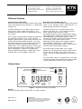
Figure 1: Location of terminals and controls
General
General connection details for all models are shown in Figure 1.
Page 2 of 13
DA135 Rev 4
Manufacturers of
Alarm Annunciators and Systems | Sequential Event
Recorders | Display Facias | Hazardous Area Interface,
Alarm and Display Products | Signal Conditioning &
Trip Amplifiers | Process Instrumentation
ISO 9001
FM 14290