1
RTK Instruments Limited
St James Business Park,
Knaresborough, North Yorkshire,
England. HG5 8PJ
Glanding
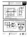
The unit cable termination section contains four gland
holes in the casing fitted with four blanking plugs. After
removal of the blanking plug or plugs cable glands may
be passed through these holes onto a tapped metal
plate inside the cable termination. The plate will directly
accept 15.3Pg DIN 40430 or M20 Isometric fine thread
glands. At least 10mm of thread is needed to engage
into the plate (Allowing for 5mm case wall thickness
plus 3.175mm plate thickness). The internal plate
provides electrical continuity between all cable glands.
Users should provide suitably rated glands to either
specification above. Longer thread length glands will
be required if a backing or lock nut is considered
necessary. To maintain IP rating we recommend that
metal glands with rubber O-ring seals be used.
The case itself has a clearance hole of 20.5mm and the
internal plate may be removed thus allowing other types
of gland to be fitted provided the case itself is not
affected. If the internal plate is removed, lock nuts will
be required for each gland and any remaining blanking
plugs. If electrical continuity between the glands is
required then it must be established by other means
e.g. A tagged washer under the lock nut.
All unused holes must be blanked off. Threaded
blanking plugs are supplied fitted in 4 positions.
Labelling
The beacons are shipped with the following labels:• A label showing the connection details on the inside
of the terminal housing lid
• A label marking with the appropriate Serial No.and
manufacturing date again inside the terminal
housing.
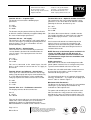
LED BEACON TYPE: DA135-XX-YY
EEx ia IIC T6 Tamb=55°C CERT No.Baseefa03ATEX0669
TERMINAL SK1&2&14 - Ui = 28V, Ii = 110mA, Pi = 0.8W
TERMINALS SK3&4, SK5&6&13 - Uo = Ui, Io = Ii, Po = Pi (SK1&2)
TERMINALS SK7&8, 9&10 - Ui = 40V, Ii = 450mA, Pi = 1.3W
TERMINALS SK11&12 - Uo = Ui(SK1&2), Io = 6mA, Po = 40mW
KNARESBOROUGH UK
INSTRUMENTS HG5 8PJ
II 1 G
1180
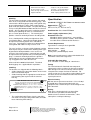
Figure 4: Certification label.
•
The certification label (Figure 4) on the top of the
unit shows all relevant safety information, and code
letters indicating LED colour(s).
Page 6 of 13
DA135 Rev 4
Telephone: +44 (0)1423 580500
Facsimile: +44 (0)1423 580501
Web: www.rtkinstruments.com
Email: enquiry@ rtkinstruments.com
Specification
Standards: CENELEC BS EN50014 & 50020 & 50284
Approved for :
II 1G
o
o
EEx ia IIC T6 (Ta -20 C to +55 C)
Certificate No : Baseefa03ATEX0669
Power supply requirements (Vin)
Hazardous area use
All models (with a zener barrier ) : 24 to 28VDc
All models (with a galvanic isolator) : 20 to 28VDC
See table A for recommended IS Interfaces.
Current Requirements
Typical when set to triple flash @24VDC
Without Sounder 20mA
With Sounder
45mA
Steady State (Acknowledged): 45mA
Note: Current requirement is reduced for double flash
and further reduced for single flash.
Selectable Re-alarm delay
User selectable re-alarm delay of 1-60 minutes.
Fusing
The Terminal board is fitted with two component
approved fused, these protect the internal electronics
from damage if the unit is incorrectly connected and
also protect the output circuit to the Sounder. For
safety reasons these must not be replaced but instead
the whole unit or terminal board returned to RTK for
repair/replacement.
Electrical Safety
Will not store or generate more than 1.5V, 0.1A, 20µJ
or 25mW when connected to intrinsically safe
equipment with a maximum open circuit voltage of not
more than 28V.
Casing
GRP (glass reinforced plastic) casing to IP65.
Translucent acrylic dome for LED housing.
Good resistance to hostile environments, saline
atmospheres and impact damage.
Manufacturers of
Alarm Annunciators and Systems | Sequential Event
Recorders | Display Facias | Hazardous Area Interface,
Alarm and Display Products | Signal Conditioning &
Trip Amplifiers | Process Instrumentation
ISO 9001
FM 14290