1
RTK Instruments Limited
St James Business Park,
Knaresborough, North Yorkshire,
England. HG5 8PJ
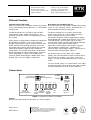
Terminal SK1 & 2 – IS power input.
The interface must match the following input
parameters:
Ui = 28V
Ii = 110mA
Pi = 0.8W
Telephone: +44 (0)1423 580500
Facsimile: +44 (0)1423 580501
Web: www.rtkinstruments.com
Email: enquiry@ rtkinstruments.com
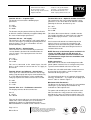
Terminal SK13 & 14 – Optional sounder connection.
This terminal has the same maximum power safety
parameters as the Zener Barrier or Galvanic Isolator
powering the beacon, therefore they are:
Uo = 28V
Io = 110mA
Po = 0.8W
The beacons may be powered from any Zener Barrier
or Galvanic Isolator certified by an approved body with
the same or lower output parameters.
Terminals SK3 & 4 – 24V supply.
This interface is for connection to a 24V supply within a
safe area, this input is specially designed to protect the
internal circuitry. For use in a hazardous area this
terminal will not be used.
Terminal SK5 & 6 – Control power
These terminals are connected directly to terminals
1 & 2 to allow the beacon to be controlled from the
same IS supply. The output parameters for these
terminals are:
Uo = 28V
Io = 110mA
Po = 0.8W
This can be connected to the control inputs, but will
draw a small amount of current from the IS supply to
the Beacon.
Terminal SK7 & 8 and SK9 &10 – Control input
These inputs are isolated and certified as non-energy
storing (Ceq=0,Leq=0) and may be connected into any
IS system without affecting the safety, provided the
safety input parameters of the unit are not exceeded.
Ui = 40V
Ii = 450mA
Pi = 1.3W
Terminal SK11 & 12 – Pushbutton connection
The output parameter for this terminal are:
This allows direct connection to a suitable sounder.
The sounder should be an intrinsically safe sounder,
with suitable input parameters, such as the RTK
DA132.
If the beacon and sounder are mounted apart, for
intrinsic safety assessment the capacitance and
inductance of the interconnecting cable should be
added to that of the cable connecting the barrier or
Isolator to the beacon.
NOTE: Because of the limited power available in IS
circuits, the LED’s flash rate will decrease on
systems with a Sounder connected. Because of
this limitation the single flash rate should be used
in these situations.
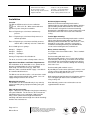
Cable connections
Connections to the unit are made through four cable
glands (20mm Isometric fine or 13.5Pg threads) into a
separate terminal board at the base of the unit.
Remove the unit cable termination section front cover
by releasing the two captive screws to expose the
terminals for wiring up the unit.
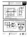
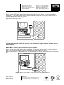
The terminal board consists of 7 two-way rising clamp
terminals, numbered 1 – 14, capable of accepting up to
2
2.5mm cable as shown in Figure 1.
Maximum Cable Parameters
The DA135 can be connected to any IS system without
affecting the system Group Classification or any
insulation or cable requirements.
The power and control inputs are isolated from each
other, therefore the safety parameters of the cables
depend on the source of supply or control signal. The
supply is 24VDC nominal via an IS barrier or interface.
Uo = Ui
Io = 6mA
Po = 40mW
They may be connected to any mechanically operated
switch in the same hazardous area as the beacon
providing the switch has IP20 Protection and can
withstand 500Vrms insulation test to earth for 1 minute.
Page 3 of 13
DA135 Rev 4
Manufacturers of
Alarm Annunciators and Systems | Sequential Event
Recorders | Display Facias | Hazardous Area Interface,
Alarm and Display Products | Signal Conditioning &
Trip Amplifiers | Process Instrumentation
ISO 9001
FM 14290