1
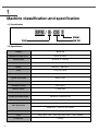
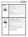
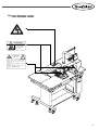
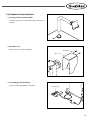
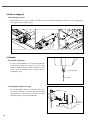
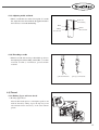
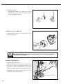
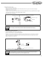
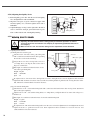
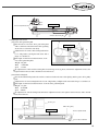
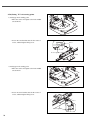
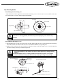
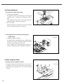
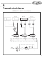
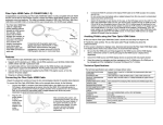
R
SPS/S-CV1
Automatic Cap Visor
Sewing Machine
썬스타산업봉제기계주식회사
1) FOR AT MOST USE WITH EASINESS,
PLEASE CERTAINLY READ THIS MANUAL
BEFORE STARTING USE.
2) KEEP THIS MANUAL IN SAFE PLACE
FOR REFERENCE WHEN THE MACHINE
BREAKS DOWN.
MME-060105
lity
a
u
tQ
Besst Pricevice
Be st Ser
Be
1. Thank you for purchasing our product. Based on the rich expertise and
experience accumulated in industrial sewing machine production, SUNSTAR
will manufacture industrial sewing machines, which deliver more diverse
functions, high performance, powerful operation, enhanced durability, and
more sophisticated design to meet a number of user’s needs.
2. Please read this user’s manual thoroughly before using the machine. Make
sure to properly use the machine to enjoy its full performance.
3. The specifications of the machine are subject to change, aimed to enhance
product performance, without prior notice.
4. This product is designed, manufactured, and sold as an industrial sewing
machine. It should not be used for other than industrial purpose.
R
SUNSTAR MACHINERY CO., LTD.
Contents
1. Machine Classification and Specification ------------------------------------------------------ 4
1.1 Classification-------------------------------------------------------------------------------------- 4
1.2 Specification ------------------------------------------------------------------------------------- 4
2. Safety Rules-------------------------------------------------------------------------------------------- 5
2.1 Safety Indication --------------------------------------------------------------------------------- 5
2.2 Delivery-------------------------------------------------------------------------------------------- 6
2.3 Installation----------------------------------------------------------------------------------------- 7
2.4 Operation ------------------------------------------------------------------------------------------ 7
2.5 Repair ---------------------------------------------------------------------------------------------- 8
2.6 Safety Label Type-------------------------------------------------------------------------------- 8
2.7 Label Attachment Location--------------------------------------------------------------------- 9
3. Basic Assembly-------------------------------------------------------------------------------------- 10
3.1 Name of Each Part ----------------------------------------------------------------------------- 10
3.2 Sewing Machine Installation------------------------------------------------------------------ 12
3.3 Peripheral Device Installation ---------------------------------------------------------------- 13
4. Machine Operation --------------------------------------------------------------------------------- 15
4.1 Electric Power Setting ------------------------------------------------------------------------- 15
4.2 Oil Supply --------------------------------------------------------------------------------------- 16
4.3 Needle -------------------------------------------------------------------------------------------- 16
4.4 Thread -------------------------------------------------------------------------------------------- 17
4.5 Transfer Device --------------------------------------------------------------------------------- 20
4.6 Trimming Device------------------------------------------------------------------------------- 27
4.7 Motor Installation and Adjustment ---------------------------------------------------------- 29
4.8 Clamp Adjustment ----------------------------------------------------------------------------- 30
4.9 Clamp Operation ------------------------------------------------------------------------------- 30
4.10 Pattern Image Insertion----------------------------------------------------------------------- 31
5. Maintenance & Repair----------------------------------------------------------------------------- 32
5.1 Regular Checkup ------------------------------------------------------------------------------- 32
5.2 Lubrication -------------------------------------------------------------------------------------- 32
5.3 Cleaning------------------------------------------------------------------------------------------ 34
6. Pneumatic Circuit Diagram ---------------------------------------------------------------------- 35
7. Trouble Shooting ------------------------------------------------------------------------------------ 36
3
1
Machine classification and specification
1.1) Classification
SPS / S- CV 1
Standard
Special
Cap Visor
1.2) Specification
Category
SPS/S-CV1
Needlework scope (X,Y)
300mm X 180mm
Sewing speed
Maximum of 1,500spm
Stitch length
0.1~12.7mm
Needle
MR5 DP17, MR4 DP17
Hook
Large rotary hook
Presser foot lift amount
Maximum of 20mm
Presser foot stroke
4mm(0~7mm)
Trimming device
Basic supply
Emergency switch
Basic supply
Memory device
3.5 FDD(2HD)
Possible input pattern number
Maximum of 691 pattern
Possible input needle number
Maximum of 360,000 needle
Reduction/expansion ratio
1~400%(0.1% STEP)
SPS/B Series : 500W direct drive AC servo motor
Main drive motor
SPS/B Series : 500W AC Servo Motor
4
Transfer system
Transfer by stepping pulse motor
Power
Simple-phase 110V ~ 240V, triple-phase 200V ~ 440V, 50/60Hz
Air pressure
0.49Mpa
2
Safety rules
2.1) Safety indication
Safety Rules define caution , danger , warning in this manual and indicate that failure to obey the rules may bring
damages, personal and physical, or machine breakdown.
No.
Name
Caution
Contents
Danger of personal or physical damages from mishandling
CAUTION
Warning
Danger of death or serious injury from mishandling
Danger
Danger of death or serious injury and other high level of serious
condition from mishandling
WARNING
DANGER
5
2.2) Delivery
Danger indication
Explanation
Machine should be carried by those who know safety instruction and rule well and
the following rules should be obeyed.
2.2.1) by Human Delivery
Wear hard safety boots and hold machine tightly on both sides.
DANGER
2.2.2) by Fork-Lift Truck
1) Truck should be strong and large enough to hold machine weight and carry it.
2) Use palette and adjust fork-arm to the center of machine (the center of left and right sides),
and then lift it carefully
Prevent
people from
passing by
and remove
obstacles
under
machine.
WARNING
6
Keep machine horizontal to prevent its deformation people’s
exposure to danger in case of using delivery equipments such as
fork-lift truck or crane.
2.3) Machine
installation
CAUTION
2.4) Machine Operation
WARNING
Wrong machine Installation may cause malfunction & breakdown and other physical
damages so comply with what follows.
1) Workbench or table should be strong enough to hold machine weight (see face plate)
2) Implement regular check-up with Air Conditioner as dust and humidity cause
contamination and corrosion.
3) Keep machine out of direct sunlight. (Long exposure to direct sunlight is a source of
color change and deformation.)
4) Leave at least over 50cm space to left and right sides of machine to allow enough
repair space.
5) Explosion accident : To avoid explosion, stop operation when there is combustive
material in the air.
6) Work light: Lighting doesn’t come with machine so that lighting should be separately
installed for machine operation.
7) Subversion danger : Don’t place machine at an unstable stand or table which will
give serious shock to people and machine if it falls down. Sudden stop while moving
machine or exterior shock may cause subversion.
SPS/S-CV1 is manufactured to sew textile and its similar texture. Machine body has
caution and warning stickers at each danger part to call attention to safety indication,
which should be kept in mind and obey what follows in operating machine.
1) Read this manual and fully understand how to operate it before use.
2) Have safety outfit on. A long hair, a necklace, a bracelet or a wide sleeve may get
jammed into machine. Slip-proof shoes are also necessary.
3) Check operation scope in order for machine not to encounter obstacles in operation
4) Keep a hand or a head away from accident-vulnerable parts (needle, hook, thread
lever, pulley).
5) Don’t remove safety cover protecting pulley or shaft for a user’s safety while
operating.
6) When dismantle electric box including control box, make sure electricity is blocked
and power switch is “off”.
7) When rotate upper shaft with hands, make sure power switch is “off”.
8) Ensure that machine stops when thread a needle or until after-work check.
9) Failure to obey what follows will bring physical damages including malfunction &
breakdown. Comply with the following instruction.
- Don’t place things on machine table.
- Don’t use bent or end-damaged needle.
- Use palette suitable for work condition.
7
When repair is needed, it should be made by a designated A/S technician only who is
trained in our company.
2.5) Repair
1) In order to maintain machine such as cleaning and repair, make sure to block main
power and wait for four minutes during which electricity is completely discharged.
DANGER
CAUTION
Wait for ten minutes for main shaft motor and X/Y drive box to
be completely discharged after main power is blocked.
2) Don’t change specification or parts without consultation with our company otherwise
safety is threatened during operation.
3) Use SWF pure authentic parts for repair and parts replacement.
4) After repair, reinstall all the safety covers that were detached during repair.
2.6) Safety Label Type
CAUTION
경 고
Do not operate without finger guard and
safety devices. Before threading, changing
bobbin and needle, cleaning etc. switch off
main switch.
손가락 보호대와 안전장치 없이 작동하지
마십시오.
실, 보빈, 바늘교환시나 청소전에는 반드시
주전원의 스위치를 꺼 주십시오.
WARNING
Injury may be caused by winding.
Be sure to turn off the power
before cleaning, lubricating,
adjusting or repairing.
8
Do not operate without finger guard and safety devices. Before threading,
changing bobbin and needle, cleaning etc. switch off
main switch.
Injury may be caused by winding.
Be sure to turn off the power before cleaning, lubricating, adjusting or
repairing.
2.6) Label Attachment Location
WARNING
Injury may be caused by winding.
Be sure to turn off the power
before cleaning, lubricating,
adjusting or repairing.
CAUTION
경 고
Do not operate without finger guard and
safety devices. Before threading, changing
bobbin and needle, cleaning etc. switch off
main switch.
손가락 보호대와 안전장치 없이 작동하지
마십시오.
실, 보빈, 바늘교환시나 청소전에는 반드시
주전원의 스위치를 꺼 주십시오.
9
3
Basic Assembly
3.1) Name of each part
3.1.1) Each part
③
⑪
⑤
②
⑩
⑨
⑧
①
⑫
④
⑦
⑥
10
1
Power ON/OFF
7
Clamp pedal
2
Arm
8
Clamp button
3
Table
9
Sewing start button
4
Control box
10
Emergency stop switch
5
Operation box
11
Thread stand
6
Sewing start pedal
12
Clamp
3.1.2) Inside of control box
fan
Floppy disk
drive
Step motor
drive board
Power board
Main shaft
motor drive
board
Transformer
IO board
386 CPU board
11
3.2) Sewing machine installation
3.2.1) Installation condition
1) Don’t use if it accounts for more than 10% of rating voltage to prevent wrong operation-induced accident.
2) Check designated pressure for devices using air pressure including A-cylinder to prevent wrong operation-induced
accident.
CAUTION
Comply with installation condition of this manual for the best operation.
Otherwise there will be unexpected breakdown.
3) For operation : 0° 40°C (32° 104°F)
4) For maintenance : -25° 55°C (-13° 131°F)
5) Humidity
- relative humidity : within 45 85%
3.2.2) Electricity Installation Condition
Power voltage should be within 10% fluctuation of rating voltage
WARNING
1) Power voltage
- Voltage should be within 10% fluctuation of rating voltage
- Frequency should be within 1% of rating frequency(50/60Hz).
2) Electromagnetic waves noise
- Separate electric power with strong magnetic and high wave products and never keep both of them close.
3) Don’t make water and coffee enter into control box and motor.
4) Don’t drop control box and motor.
3.2.3) Table stand installation
1) Table fixing
- Insert shock-absolving rubber into level adjuster and raise it until caster moves freely.
- After installation, fix level adjuster by tightening nut.
2) Table height adjustment
- Adjust height by loosening bolt slightly attached to table and tight it again completely.
Bolt
Nut
Level adjuster
Shock-absolving rubber
Caster
12
3.3) Peripheral Device Installation
3.3.1) Operation box stand assembly
- Combine operation box stand with a table and then fix it
with bolt.
3.3.2) Motor cover
- Attach motor cover with a turnbuckle.
Turnbuckle
Motor cover
3.3.3) Standing pedal installation
- Connect standing pedal plug to control box.
Standing pedal
13
3.3.4) Thread stand installation
- Install thread stand on a table.
While attaching using tools, be careful not to drop one of the parts and get injured.
CAUTION
3.3.5) Installation of pneumatic controlling parts
1) Filter regulator
Install a filter regulator at the bottom of a table support with a bolt.
When connecting an air hose, use a quick joint socket to link it to the quick joint plug attached on a regulator.
2) Solenoid valve
Fix a solenoid valve to a table support with a set bolt.
Finger valve
Hose
Plug
Quick joint socket
CAUTION
14
1) Adjust proper pneumatic pressure to 5~5.5kgf/cm (0.49~0.54MPa).
2) When the pressure drops less than 4kdf/cm, machine stops operating with an error
message. (Error message: Err 24 (Low Pressure!)
3) When you turn off the finger valve after use, residual air is automatically emitted and
remaining pressure indicates 0Mpa (0kgf.cm).
4
Machine Operation
4.1) Voltage set-up
1) Detach a cover of electric controlling pattern sewing
machine to check whether components are the same
with those in the picture below.
2) Check whether location of power voltage switching
connector in electric board and transformer use are
chosen properly to match with input voltage shown in
table1 and table 2 shows.
Ex) If power voltage is 220V, the transformer model
should be “SPS-□□□□-220”and the location of
power voltage switching connector,“JP5”.
The transformer model can be found in a sticker
attached on the upper part.
Power voltage
95V ~ 105V
Location of power voltage
switching connector
JP4
106V ~ 115V
JP3
116V ~ 125V
JP2
200V ~ 230V
JP5
231V ~ 245V
JP4
345V ~ 415V
JP3
416V ~ 480V
JP2
Input voltage
[Table1. Location of voltage switching connector]
Machine model
SPS /S -CV1
100V ~ 120V
SPS-1306-110(for common use)
220V ~ 440V
SPS-1306-110(for common use)
3) Check whether power switch is for a single-phase or for a triple-phase.
4) If 2) and 3) are not available, it may be in danger of breakdown. Thus, take the following measures to avoid machine
damage.
Ex) In case the location of power voltage switching connector is not appropriate,
- Separate transformer connector CN7, CN8, and CN9 from power board.
- Switch power voltage switching connector to the proper location of table1.
- Reconnect transformer connector CN7, CN8, and CN9 to power board.
If transformer and power switch do not conform to specification, exchange or repair in the
store you purchase them.
CAUTION
15
4.2) How to supply oil
4.2.1) oil supply location
In the first driving of a sewing machine, check the amount of remaining oil through the window of each oil supply place,
and complement the insufficient part.
4.3) Needle
4.3.1) Needle attachment
Loosen a needle turnbuckle of a needle bar and push the
needle until its upper tip reaches the end of needle
insertion mouth of the bar with the needle long hole
facing forward. And then, fix the needle by using a
needle fixing screw.
Needle turnbuckle
Needle
4.3.2) Adjusting needle bar height
Loosen turnbuckle holding a needle bar holder at the
lowest point of the bar to make the upper line matching
with specification conform to the lower face of a needle
bar bushing. Then, screw the bar turnbuckle.
Turnbuckle
DPX17
Less than #22
16
DPX15
DPX17
More than
#22
4.3.3) Adjusting needle and hook
When a needle bar rises at the lowest point of a needle
bar, align the lower line which fits the applied needle to
the lower face of a needle bar bushing.
Needle bar
lower bushing
DPX5
DPX17
Less than #22
DPX17
More than #22
4.3.4) Threading a needle
Thread a needle after moving a thread take up lever to
the highest point, when holding a thread like ① for thick
materials, and like ② for knitwear, general and thin
materials.
① For thick materials
② For general materials
4.4) Thread
4.4.1) Holding Upper and lower thread
1) Hooking upper thread
Place the thread take up lever on the highest position, and
hold the thread by making it pass through major and
minor thread tension control ass’y as the same with the
picture.
17
2) Hooking lower thread
Put bobbin into bobbin case. Then, pass a thread
through a thread hole, and hook the thread under a
tension adjusting plate spring.
4.4.2) How to separate bobbin case
Grab the handle of bobbin case, and push it into a hook
until a sound is heard.
Operating machine while the bobbin case does not enter fully can lead to tangled thread or
make bobbin case spring out.
CAUTION
4.4.3) How to adjust tension
1) Adjusting upper thread tension
Turn the tension nut of major and minor thread tension
control ass’y clockwise to strengthen the tension of an
upper thread; turn them counterclockwise to weaken the
tension. To control thread tension, adjust the tension
depending on the sewing conditions such as sewing
materials, threads, and stitch numbers.
Strong
Minor thread tension control ass’y
Weak
Strong
Major thread tension control ass’y
Weak
18
2) Adjusting thread take up lever spring tension
Adjust major thread tension control ass’y shaft by turning
a bolt with a driver. Turn the bolt clockwise to strengthen
the tension of a thread take up lever spring; turn it
counterclockwise to weaken the tension. (Standard
moving length: 6~8mm, tension: 30~50g)
Strong
Weak
Thread take up lever spring
3) Adjusting lower thread tension
Turn tension adjusting screw of bobbin case clockwise
to strengthen the tension of lower thread; turn it
counterclockwise to weaken the tension.
Strong
Weak
Tension adjusting
screw
4.4.4) How to wind lower thread
1) Insert bobbin to bobbin winder drive shaft of bobbin
winder base attached to a top cover.
2) Attach bobbin winder lever on bobbin, and press pedal to
operate machine.
3) After bobbin winder lever falls from bobbin, use a
bobbin winder knife to cut the thread.
19
4.4.5) Adjusting bobbin winder amount
Bobbin
Use the initial position of a bobbin winder adjusting plate. If
bobbin winder amount is large, loosen a turnbuckle of
adjusting plate to turn it into A direction and if the amount is
small, turn it into B direction.
A
B
Bobbin winder adjusting plate
4.4.6) Adjusting location of bobbin winder drive
wheel
Upper shaft
1mm
Adjust the location of bobbin winder drive wheel to have a
1mm distance from presser foot drive cam. Then, screw a
turnbuckle.
Presser foot drive cam
4.5) Transfer device
4.5.1) Adjusting height of presser foot
1) Loosen the turnbuckle of presser foot at the lowest point
of a needle bar.
2) Adjust presser foot height depending on thickness of
sewing materials, and tighten the turnbuckle.
20
Turnbuckle
Bobbin winder
drive wheel
4.5.2) Adjusting presser foot device
1) Align the end of presser foot cam with the center of
upper shaft carved mark, and the carved line of the cam
with the carved mark. And then tighten a turnbuckle.
①
Carved
mark
Upper shaft
When presser foot drive cam is not properly placed, its vertical movement timing of the
foot is not right, which may cause friction between the needle plate and the foot.
CAUTION
17mm
2) Adjusting presser bar height
Adjust presser bar end to 17mm in the bar holder. And
then tighten a turnbuckle after checking a needle passes
through the center of the presser foot.
Presser
bar
Presser bar holder
Presser foot
Tighten presser bar turnbuckle with 40~45kgf/cm pressure.
Excessive pressure may cause deformation of the bar and problem in operation.
WARNING
3) Adjusting presser foot adjusting arm
Make a space between location link stopper and fixing link hinge screw of presser foot movement by loosening
location link stopper screw.
Loosen fork link screw and place the foot link hinge screw to the right side of the foot adjusting arm. And then tighten
the link hinge screw.
Place needle bar at the lowest point by turning a hand pulley.
Raise presser bar and tighten the fork link turnbuckle to set the distance to allow 4mm between the bar holder and the
bar bushing
Adhere the location link stopper closely to the foot moving link hinge screw by tuning the stopper turnbuckle.
Tighten fork link screw and check to make sure that there is no extra space in vertical movement of the foot adjusting
arm. Adjust the foot stroke after checking the tightening condition of screws.
21
CAUTION
1) Insufficient space between presser bar holder and presser bar bushing may interrupt
operation and make a noise.
2) Failure to tighten screw completely after adjusting can bring damage to the machine during
operation.
3) If the foot moving link hinge screw does not adhere to the end of location link stopper
closely, a noise can become louder because the machine trembles during operation.
Presser adjusting arm
Turnbuckle
Stopper
Hinge screw
4mm
Presser bar holder
Presser bar bushing
4) Adjusting presser foot stroke (upper, lower movement
adjustment)
After loosening the foot hinge screw, move presser foot
adjusting arm to A direction to make the foot stroke
bigger, and to the B direction to make the presser foot
stroke smaller. (Stroke is set at 4mm in a released
machine to a market.)
B
A
Hinge screw
4.5.3) Adjusting thread release components
1) Setting thread release notch location
Place the right side of long hole of thread release notch to
reach the circumference of the thread release notch
turnbuckle. And then fix it with a turnbuckle.
Turnbuckle
Notch
If location is not properly set, remaining thread amount may be smaller or irregular. And also
thread may fall out of needle at the beginning of sewing.
CAUTION
22
2) Setting thread release stopper
Remove thread release return spring.
Adjust the space between thread trimmer drive link and thread release lever pin to 0.3mm after loosening the
turnbuckle of thread release stopper.
To make narrow the space between thread trimmer drive rink and thread release lever pin, push thread release stopper
to the right, and to make the space wide, push the stopper to the left.
Hook thread release return spring.
Thread release lever pin
Thread trimmer drive rinkThread release return spring
0.3mm
Thread release stopper
Turnbuckle
Widening
Narrowing
For your safety, use tools when you attach or detach thread release return spring.
WARNING
3) Adjusting opening of the thread guide disk
Loosen the turnbuckle of thread release adjusting plate.
Perform a trimmer function to open the thread guide disk.
Adjust the opening of thread guide disk to 0.6~0.8mm for general materials and to 0.8~1mm for heavy materials.
Wider angle of thread release adjusting plate makes the disk opening wide and narrower angle makes it narrow.
Tighten a turnbuckle after adjustment.
Widening
Narrowing
Opening
Turnbuckle
Thread release adjusting plate
Thread release rink direction
Thread tension control ass'y direction
If the thread guide disk is not open enough, remaining thread amount may be smaller or
irregular. And thread guide disk may not be completely closed.
CAUTION
23
4.5.4) Adjusting hand pulley device
Upper shaft
1) Put hand pulley gear in line with the end of hand pulley
axis, and tighten them with a turnbuckle.
2) Align the extra space of gears connected to upper shaft
and hand pulley axis, and then tighten them with a
turnbuckle.
3) Adjust bushing by moving it to the right and to the left in
order to minimize entangle generated between gears
when a roller rides the end of hand pulley bushing.
Hand
pulley
bushing
Hand pulley axis
Roller
4.5.5) Adjusting drive belt tension
WARNING
1) Adjusting drive belt tension affects sewing quality and machine operation so ask the
service to those who are trained in our company or equivalently qualified technicians in
our company.
2) Make sure to turn “off” the machine during tension adjustment of each drive belt.
1) Adjusting X-axis tension
(1) Timing belt of motor drive part
Check tension of X-motor drive part timing belt
with a sound wave belt tensiometer after separating
X-axis rail cover from the main body.
Adjust X-motor drive timing belt tension to
13~14kgf when you flip the belt center with a
finger or a similar tool.
Data input of sound wave belt tensiometer of a Xmotor drive part timing belt
Weight : 40 gf/m
Wide : 20mm/#R
Span : 67
X- motor
Nut
Tension
adjustment
bolt
Minor drive pulley
Drive pulley
Timing belt
To adjust tension of X-motor drive timing belt, loosen the nut tightened to tension adjustment bolt and turn
adjustment bolt clockwise for tension increase while motor-fixing bracket is pushed to the moving direction of the
bolt, and turn it counterclockwise for tension decrease.
(2) X–axis transfer timing belt
Check tension of X – axis transfer timing belt with a sound wave belt tensiometer after moving frame attachment
plate to the right completely.
Adjust tension of X – axis transfer timing belt to 11~12kgf when you flip the belt of its center with a finger or a
similar tool.
Data input of a sound wave belt tensiometer of a X-axis transfer timing belt
Weight : 3.8 gf/m
Wide : 18mm/#R
Span : 513mm
To adjust tension of X-axis transfer timing belt, loosen the screw of tension adjustment axis and adjustment nut, and
adjust the bolt to a optimum tention level. Turn adjustment bolt clockwise for tension increase and
counterclockwise for tension decrease.
24
Tension adjustment axis screw
Tension adjustment bolt
F : 11~12kgf
X frame attachment plate
2) Adjusting Y-axis tension
ⓑ
(1) Y-motor drive part timing belt
ⓒ
Check tension of Y-motor drive part timing belt
F : 12~13kgf
with a sound wave belt tensiometer after separating
X-axis rail cover from the main body.
ⓓ
Adjust tension of Y-motor drive timing belt tension
to 12~13kgf when you flip the belt center with a
finger or a similar tool.
Data input of sound wave belt tensiometer of a Yⓐ
motor drive part timing belt.
Weight : 4.0 gf/m
Wide : 20mm/#R
Span : 112mm
To adjust tention of Y-motor drive timing belt, loosen fixing screws (4 places), turn tension adjustment screw to the
right for tension increase and to the left for tension decrease.
(2) Y-transfer timing belt
Check a Y-transfer timing belt tension with a sound wave belt tensiometer after placing X-drive part to drive pulley
part.
Adjust tension of Y-axis timing belt tension to 30~32kgf when you flip the belt center with a finger or a similar tool.
Data input of sound wave belt tensiometer of a Y-axis drive part timing belt.
Weight : 3.8 gf/m
Wide : 18mm/#R
Span : 230mm
To adjust tension of Y-axis timing belt, turn tension adjustment screw to the right for tension increase and to the left
for tension decrease.
X drive part
Minor drive pulley
F : 30~32kgf
Tension adjustment bolt
Tension base turnbuckle
25
4.5.6) Setting X-Y axis starting points
1) Setting up Y-axis starting point
Move the center of feed plate to be in the middle
toward X-axis.
Loosen X-censor bracket nut to be the center of
censor, and then tighten fixing screw.
Sensor
X sensor plate
Nut
2) Setting up Y-axis starting point
Move the center of feed plate to be in the middle
toward Y-axis
Loosen Y-censor bracket nut to be the center of
censor, and then tighten fixing screw.
Sensor
Turnbuckle
X censor plate
26
4.6) Trimming device
4.6.1) Setting thread trimming cam
Adjust the distance between upper shaft collar and thread trimming cam to 2.5mm. Locate the cam carved line in the same
line with the shaft carved mark, and then tighten the turnbuckle.
Thread trimming cam
Carved line
2.5mm
Carved mark
Upper shaft
Upper shaft
Upper shaft collar
①
If the cam is in a wrong position, the trimmer may not work properly, or the machine may
be stuck.
CAUTION
4.6.2) Adjusting link stopper screw
1) Check whether there is enough space between the cam roller and the both sides of the cam when push the thread trimming
drive link toward the cam direction at the lowest level of needle bar within the cam operating area.
2) With the roller inserted into the cam operating area, adjust the end part of the link stopper screw to reach the tightening
part of the trimming connecting rod and then tighten nut.
CAUTION
1) If there is no enough space between the roller and the both sides of the cam, the trimmer
may not work properly, or the machine may be stuck at the beginning of sewing or during
trimming.
2) If the link stopper screw is in a wrong position, the cam roller may return to its original
position slowly after trimming and the screw may not be tight enough during sewing.
Enough space
Enough space
Thread trimming drive
cam roller
Thread trimming drive link
Thread trimming cam
Connecting rod
Link stopper screw
Link stopper screw
Nut
Thread trimming connecting rod
27
4.6.3) Setting thread trimming shaft position
1) Loosen the turnbuckle of thread trimming drive link and
the turnbuckle of thread trimming shaft collar.
2) Align thread trimming shaft with A part of the arm.
3) Tighten turnbuckle
Thread
trimming
cam
Thread
trimming drive
link
Thread trimming shaft
Turnbuckle
4.6.4) Setting link stopper position
1) When thread trimmer is not working, loosen the
turnbuckle of thread trimming drive link. Adjust the
distance between the link and the link stopper notch to
0.3mm.
Turnbuckle
0.3mm
Thread
trimming
drive link
0.3mm
Thread trimming drive link stopper
If position is not correct, trimmer may not work properly, or the machine may be stuck.
CAUTION
4.6.5) Setting thread trimming solenoid position
1) Loosen the turnbuckle of thread trimming solenoid bracket. Adjust the distance between thread trimming shaft and the
rotary link of thread trimming solenoid to 0.5mm, and tighten the turnbuckle.
2) Loosen the rotary link turnbuckle of trimming solenoid and manually drive the link to adjust thread trimming shaft to
6.8mm and tighten the turnbuckle.
3) Check to make sure that the collar is returned to its original position when the rotary link returns to its first position.
Turnbuckle
Thread trimming solenoid bracket
Thread
trimming
solenoid
Turnbuckle
0.5mm
Rotary link of thread trimming solenoid
Rotary link of thread
trimming solenoid
6.8mm
Thread trimming shaft
If the position is not correct, the trimmer return may become slow, or the machine doesn't give
the best sewing due to slow thread release.
CAUTION
28
4.6.6) Adjusting moving and fixing mes
1) Adjust the distance A between thread dividing point of moving mes and needle plate hole to the same figure as given with
lever adjustment screw when needle bar stops moving.
B
B
A
4.5mm 0.5mm
Fixing mes
Needle plate cover
A
Moving mes
If the position is not correct, thread can't be trimmed properly or remaining thread amount
may get smaller.
CAUTION
4.7) Installing and adjusting direct motor
Turnbuckle #1
Servo motor
4.7.1) Attaching coupling
O-Ring
1) Attaching servo motor coupling
With coupling turnbuckle locating exactly at the cutting
part of servo motor, adjust the distance between the
coupling and the motor to 0.7mm, and tighten the
coupling turnbuckle.
2) Attaching coupling to upper shaft
With coupling turnbuckle locating exactly at the cutting
part of upper shaft, adjust the distance closely between
Bearing O-ring and the coupling to be 2mm, and tighten
the turnbuckle.
Upper shaft
Rounding areas
Upper shaft rear bearing
Arm
Coupling
2mm
0.7mm
4.7.2) Combining motor
1) Motor combination
Combine motors carefully while making sure to align the location of motor coupling turnbuckle to that of upper shaft
coupling turnbuckle.
If the location of coupling turnbuckle is not correct, a needle does not stop in the right place.
WARNING
29
4.8) Clamp adjustment
Reducing valve
4.8.1) Pressure control of side clamp
Fixing nut
1) Solenoid valve adjustment
To adjust the pressure of side clamp use the pressure
reducing valve of a solenoid valve attached to a table’s
base.
After adjusting the pressure of side clamp properly,
fasten fixing nut to maintain the set pressure.
2) Pressure control
Turn the reducing valve clockwise to increase side clamp
pressure and counterclockwise to decrease it.
4.8.2) Adjusting forward and backward speed of
middle clamp
Speed controller
Fixing nut
1) Adjustment of speed controller
To adjust forward and backward speed of middle clamp:
turn the valve of speed controller clockwise to increase
speed and counterclockwise to decrease it.
After completion of adjusting speed properly to
operation, fasten fixing nut to maintain the set pressure.
4.9) How to operate clamp
4.9.1) Operation of clamp/start switch
Start switch
First, press clamp switch. The clamp moves to fix a visor to
a feed plate so as not to move while sewing. And then, press
start switch. The machine begins to sew on the visor fixed
to clamp.
Clamp switch
30
4.9.2) Operation of standing pedal
Press the right side of standing pedal to operate as does
clamp switch.
Press the left side of the pedal to begin sewing as does start
switch.
Standing pedal
4.10) How to insert pattern images
To insert a variety of patterns into the sewing machine
by using a floppy disk.
Floppy disk
A floppy dist available in a market can be used after formatting. Authorized disk only.
WARNING
31
5
Maintenance & repair
WARNING
1) Abide by safety rules on machine and electric safety when checking, maintaining and
repairing the machine.
2) These works should be one when the machine power is “OFF.”
5.1) Regular checkup
1) Regularly Clean, lubricate and pour grease into designated areas to maintain capabilities of the machine.
2) Check tension of each drive belt.
3) No regular checkup may cause the following problems:
Unusual abrasion of each frictional area led by insufficient lubrication and grease pouring.
Abnormal operation caused by dust and foreign substances in the drive.
WARNING
1) SUNSTAR takes no responsibility for mechanical breakdown or malfunction caused by
no cleaning and lubrication of the machine through regular checkup.
2) Cleaning period varies depending on using condition and surrounding environment.
5.2) Lubrication
5.2.1) Lubricant types
No.
Lubricant types
using areas
1
Sewing machine oils
Arm, bed, hook areas
2
Grease
X-Y feed rail
5.2.2) How to lubricate
1) Arm
Feed oil after checking the amount of remained oil in
an oil tank installed in the arm.
Feed oil in and upper side of an oil tank door.
2) Bed
After removing a rubber cork of a table’s oil tank
mouth, feed oil and then, plug up the mouth again
with the cork.
32
3) Hook
- Pull out a bobbin case and feed oil until it soaks in the
hook and its surrounding areas.
5.2.3) Removal of residual oil
Remove oil when it is full in residual oil can.
5.2.4) Grease pouring
Pour grease regularly into X-Y transfer rail.
33
5.3) Cleaning
5.3.1) Frequency and method of major parts cleaning
1) Make sure to turn the machine power is “off” before cleaning.
2) Reassemble all the parts removed for cleaning in the opposite order.
WARNING
No.
Major parts cleaning
Cleaning frequency
1
Hook area
Everyday
2
Thread take-up lever / Thread tension control assembly
3
Moving and fixing mes area
Remove dirt at moving and fixing mes by using air under needle plate.
Three times in a week
4
X-Y transfer timing pulley and timing belts
Disassemble cover first and remove dirt in each part of X-Y transfer
part by using air.
(Rotate pulley when cleaning.)
Once in a month
5
Control box and cooling fan filter
Remove cover and pull off filter. Wash the filter with running water
and dry completely in the shade to use.
Once in a week
Once in a week
①
②
③
④
⑤
④
34
6
Pneumatic circuit diagram
[ SPS/S-CV1 Air System Circuit Diagram ]
Side clamp
AIR IN
Mid clamp
Presser foot
A
B
A
B
EA
P EB
EA
P EB
P
R
A
EA
B
P EB
A
35
7
Trouble shooting
1) Machine part
No.
1
2
3
4
5
6
7
36
Problems
Problems of machine
and operation
Incorrect stop position
Needle break
Thread breakage
Causes
Solutions
excessively loose belt tension or belt damage
belt tension adjustment and belt change
power or circuit fuse disconnection
Check disconnection of major motor drive fuse
in control box and change it
disconnection from limited position of X or Y of
feed bracket
Move feed bracket to the right position (within
switch limitation)
loose main drive belt
belt tension adjustment
incorrect position of synchro
synchro position adjustment
needle damage
(bent needle, damage on the eye of needle or
hole, or worn-out or changed needle point)
new needle installation
incorrect needle setting
correct needle installation
needle and shuttle contact
needle and shuttle space adjustment
wrong threading
correct threading
wrongly inserted needle
(needle height and direction etc.)
needle replacement
damaged needle
(bent needle, damage on the eye of needle or
hole, or worn-out or changed needle point)
needle change
too tight tension on lower and upper thread
tension adjustment
excessive tension and workload at thread take-up lever spring
changing thread take-up lever spring tension and workload
flaw on thread regulating hole area of spring on
upper part spring of shuttle
replacement of new spring of shuttle upper part
bent needle use
needle change
wrong size needle for sewing thread
needle change
incorrect needle installationa
needle reinstallation
wrong needle and timing
readjustment of needle and shuttle timing
improper hole and wide space between hole and shuttle point
readjustment of needle and shuttle timing
excessive tension and workload at thread take-up lever spring
adjustment of thread take-up spring tension and workload
weak upper thread tension
adjustment of upper thread tension
weak lower thread tension
adjustment of lower thread tension
improper needle and shuttle timing
readjustment of needle and shuttle timing
loose crossed tension of moving mes and fixing mes
adjustment of fixing mes tension
worn-out knife edge hole of moving and fixing mes
changing moving and fixing mes
incorrect position of thread trimmer cam
readjustment of thread trimmer cam position
Skipped sewing
Incorrect thread
tightening
Missing thread
trimming