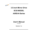
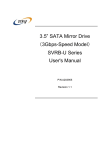
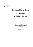
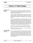
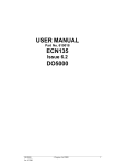
1
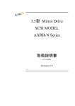
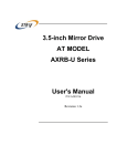
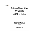
3.5-inch Mirror Drive
AT MODEL
AXRB-N Series
User's Manual
P/N A202967
Revision 1.1e
偶数ページで終了するための白紙です
3.5-inch Mirror Drive AT Model User's Manual
Introduction
Thank you for purchasing our 3.5-inch AT Model AXRB-N Series Mirror Drive.
Important Points
Please ensure you read the user's manual before use.
This manual explains important points, methods of handling, and configuration methods for all
functions, in order that you can make full use of the capabilities of the 3.5-inch Mirror Drive AT
Model AXRB-N Series. In the event you should have any problems with the Mirror Drive, please
refer to this user's manual.
“6. Handling Faults” on page 15 offers solutions for most of the problems that occur during use of the
Mirror Drive.
Storage of Container and Packaging Materials
The container and packaging materials protect the Mirror Drive from shock during transportation.
After unpacking the Mirror Drive, please keep the box and use it if you need to send the drive for
repair.
Furthermore, this product is sealed in an antistatic bag at the time of shipping, so only open the bag
immediately before setup or use.
Records of Product Name, Version, and Serial Numbers
Before installing the Mirror Drive into the host computer, please make a note of the product name,
version, and serial numbers.
For location of the product name, etc., refer to P.3 “2.1 Part Names.”
●
THIS DOCUMENT MAY NOT BE REPRODUCED OR COPIED IN WHOLE OR IN PART.
●
THE CONTENTS OF THIS DOCUMENT ARE SUBJECT TO CHANGE WITHOUT NOTICE.
●
WE HAVE MADE EVERY EFFORT TO ENSURE THE ACCURACY AND COMPLETENESS
OF THIS DOCUMENT. IF YOU FIND INACCURACIES OR OMISSIONS, PLEASE CONTACT
YOUR DISTRIBUTOR.
Copyright(c)
Storage Vision Co., Ltd
All rights reserved.
i
Storage Vision Co.,Ltd.
In order to safely use this product:
This user's manual uses the following symbols in order that you may safely use this product.
Please observe the following safety points.
About these symbols:
In order to prevent injuries to you and other people, and damage to objects when using this product,
the following symbols are used in the user's manual and affixed to the Mirror Drive.
Warning
Indicates a situation that, if not avoided, may result in death
or serious injury.
Caution
Indicates a situation that, if not avoided, may result in
physical injury or property damage.
Important
Indicates important issues and restrictions that should be
observed in order to avoid failure of or damage to the
product, or product malfunction.
About Danger / Caution Labels
Labels that have black lettering on a yellow background and that are displayed on either the exterior
or interior of the product are Warning or Caution labels that outline safety issues. Ensure that the
directions explained there are followed.
Where Warning or Caution labels are displayed that are not explained in this user's manual, ensure
that those directions are observed.
ii
3.5-inch Mirror Drive AT Model User's Manual
Warning
y In the event of any abnormalities, such as the emitting of smoke or unusual odors, immediately cut
off the power supplied to the host computer.
y In the event that any foreign objects (metals, water, liquids, etc.) should enter the product's
casing, immediately cut the power supply to the host computer.
y Do not use in hot or damp locations.
Doing so may lead to fire, electrical shock, or damage.
y Do not disassemble or modify this product.
Doing so may lead to fire, electrical shock, or damage.
y When connecting and removing this product’s cables, cut the power supply to the host computer
and any connected devices. Additionally, do not forcefully bend, twist, or pull the cables.
Doing so may lead to fire, electrical shock, or damage.
iii
Storage Vision Co.,Ltd.
Caution
y Do not use in locations subject to vibration or shock. Doing so may lead to malfunction or disk
failure.
y Subjecting the product to rapid changes in temperature may cause condensation within the unit,
which may lead to disk failure. Take measures to avoid condensation. Should condensation occur,
leave the unit switched off for a period of time, and use only after confirming that it has dried
completely.
y Do not locate the unit near equipment that generates strong electromagnetic radiation, such as
televisions or speakers. Doing so may lead to malfunction or disk failure.
y In the event of moving the host computer in which this unit is mounted, cut off the power supplied,
and ensure it is not subject to vibration or shock. Failure to do so may lead to malfunction or disk
failure.
y Repeatedly turning if the power on and off within a short period of time may cause a disk that is
spinning down to start spinning up again, causing damage to the hard disk drive spindle motor and
heads, which may shorten its operational life. When turning the power off, ensure that the drive
has sufficient time to stop spinning (approximately 20 seconds) before turning the power on again.
Even when removing a normally operating drive unit, turn the power off, and wait for a sufficient
amount of time (approximately 20 seconds) before removing the drive.
y Do not remove a normal drive unit while the power is switched on.
Removing a normally operating drive unit in this way may result to drive failed.
Furthermore, doing so may cause damage to the disk heads and platter inside the hard disk drive,
which may lead to disk failure.
y Do not leave the units unused, or store for long periods of time (three or more months) when
switched off. Doing so may lead to malfunction or disk failure.
y Do not apply pressure to the covers of the hard disk drive.
Doing so may lead to malfunction or disk failure.
y After unpacking or transport, ensure each disk drive is properly inserted before turning the power
on.
iv
3.5-inch Mirror Drive AT Model User's Manual
Important
y Ensure that important data is backed up to a suitable medium, such as tape or MO drives.
This unit is designed to use mirroring to prevent data loss even in the event of one drive unit
failing. In the event that two drive units fail simultaneously, or a non-redundant part fails, there is a
possibility of data loss. Additionally, data loss may also occur as a result of accidental deletion or
equipment damage.
y Do not obstruct the holes in the hard disk drive cover. Doing so may lead to hard disk drive failure.
y This unit uses cache memory, therefore except in emergencies, follow the operating system’s
correct shutdown procedures, or wait for at least 10 seconds after the drive access indicator has
stopped flashing, before turning off power to the unit. Failure to do so may lead to loss of data
stored in the cache memory.
y Each drive unit is controlled according to its serial number. Except when replacing controller units
or drive units, do not remove or switch around drive units. Doing so may result in the drive being
unable to start up.
y When installing in the host computer’s mounting bay, mount the unit securely using the mounting
screws provided (recommended torque 0.49 Nm).
y When one drive unit has failed, upon turning the host computer power on, the Mirror Drive may
take a maximum of 15 seconds to start. Accordingly, BIOS time out settings in the host computer
may mean that the Mirror Drive is not recognized.
v
Storage Vision Co.,Ltd.
Important Points about Static
In order to avoid damage from static, observe the following warnings when handling this unit.
y When handling this unit, touch the metal parts of the host computer, and avoid internal static.
y When handling this unit, handle the metal parts. Do not touch any exposed circuitry.
y When swapping controller units or drive units, or when that moving the unit after unpacking, place
the antistatic bag that the unit was shipped in on a flat, even surface, and place the unit on top of
that.
vi
3.5-inch Mirror Drive AT Model User's Manual
Important Points about Installing the Mirror Drive
When installing the Mirror Drive in the host computer, ensure the drive unit is installed horizontally,
as in <A> below.
Do not install the unit vertically, i.e. with the connector facing either up or down, as in <B>.
Furthermore, when installing the unit on its side as in <C>, first consult with your distributor.
<A>Drive unit in horizontal position
<B>Drive unit in vertical position
<C>Drive unit on its side
vii
Storage Vision Co.,Ltd.
[Table of Contents]
Introduction
....................................................................... i
In Order to Safely use this product: ................................................... ii
warning ........................................................................... iii
Caution
...........................................................................iv
Important .......................................................................... v
Important Points about Static ........................................................vi
Important Points about Installing the Mirror Drive ..................................... vii
Table of Contents
................................................................. viii
1. Introducing the 3.5-inch Mirror Drive ................................................ 1
1.1 Features ........................................................................ 1
1.2 About Mirroring .................................................................. 2
1.3 Cache Buffer Functions ............................................................ 2
2. External Dimensions .............................................................. 3
2.1 Part Names ..................................................................... 3
2.2 Front Elevation (With Bezel Open) ................................................... 4
2.3 Front Elevation (With Bezel Closed) ................................................. 4
2.4 External Dimensions Diagram ...................................................... 5
2.4.1 Mirror Drive ................................................................. 5
2.4.2 5-inch Bay Mirror Drive Installation Attachment .................................... 6
3. Connecting to the Host Computer .................................................. 7
3.1 Switch Settings .................................................................. 7
3.2 Installing into the Host Computer .................................................... 7
3.3 Cable Connection ................................................................ 8
3.4 Turning on Main Power ............................................................ 8
4. Settings ......................................................................... 9
4.1 Configuration Switch .............................................................. 9
4.1.1 Operating Mode
............................................................ 10
4.1.2 Ultra DMA66 Mode .......................................................... 10
4.1.3 Write Cache Mode .......................................................... 10
4.1.4 Buzzer Mode ............................................................... 10
4.2 Master / Slave Settings ........................................................... 11
5. Status Display .................................................................. 12
5.1 Indicator ....................................................................... 12
5.1.1 Access Indicator ............................................................ 12
5.1.2 Drive Status Indicator ........................................................ 12
viii
3.5-inch Mirror Drive AT Model User's Manual
5.1.3 Buzzer .................................................................... 13
5.2 External Output Signal ........................................................... 14
5.2.1 Status Output Signal ......................................................... 14
5.2.2 External LED Output Signal ................................................... 14
6. Handling Faults ................................................................. 15
6.1 Confirming Fault Status ........................................................... 15
6.2 Replacement of Drive Units ....................................................... 16
6.2.1 Replacement of 1 Drive Unit .................................................. 16
6.2.2 Replacement of Both Drive Units ............................................... 21
6.3 Controller Unit Replacement ...................................................... 24
6.3.1 When both drive units are functioning normally ................................... 25
6.3.2 When one drive unit has failed ................................................. 27
6.4 Other Malfunctions
.............................................................. 31
6.5 Data Rebuilding ................................................................. 31
Appendix A
Specifications ........................................................ 32
A.1 Main Unit Specifications .......................................................... 32
A.2 External Output Signal Specifications ............................................... 33
A.2.1 Status Output Signal ........................................................ 33
A.2.2 External LED Output Signal ................................................... 35
Appendix B
Accessories .......................................................... 37
Appendix C
Default Configuration
Appendix D
Replacement Parts .................................................... 39
................................................. 38
Information ....................................................................... 40
ix
偶数ページで終了するための白紙です
3.5-inch Mirror Drive AT Model User's Manual
1. Introducing the 3.5-inch Mirror Drive
The ADTX 3.5-inch Mirror Drive is equipped with two 2.5-inch disk drives, and uses mirroring to
protect data and ensure uninterrupted operation.
Because the host computer recognizes the Mirror Drive unit as a regular AT hard disk drive, setup of
the drive entails simply plugging in an IDE (ATA) cable.
1.1 Features
y Even in the event of one drive unit failing, the Mirror Drive will continue to operate, therefore
maintaining data integrity. After the failed disk is replaced, data rebuilding begins automatically.
y The unit uses the industry standard IDE (ATA) interface, and operates as a single AT hard disk
drive. Specific device drivers, host computer hardware, or operating systems are not required.
y Supports Ultra DMA66 mode. (maximum data transfer rate: 66MB/s)
y Large onboard cache memory for improved performance.
y Hardware mirroring, therefore there is almost no system overhead.
1
Storage Vision Co.,Ltd.
1.2 About Mirroring
Mirroring writes the same data in duplicate on two drive units. Even if one drive unit fails, the data can
be read from the other drive unit.
1.3 Cache Buffer Functions
The Mirror Drive is equipped with a large capacity cache memory. When write cache mode is on, as
soon as data is written to the cache memory, the host computer is notified that command processing
is completed. By writing multiple data together to the HDDs at only a single time, a performance
increase is realized. Setting the write cache mode on or off is done using the settings switches. It is
set as on at shipping.
Important
2
Except in emergencies, before turning off power to the unit,
follow the operating system’s correct shutdown procedures,
or wait for at least 10 seconds after both the drive access
indicator or the drive status indicator have stopped flashing.
Turning off of power while the access indicator or drive status
indicator lamps are on (or flashing) may result in the loss of
any data remaining in the Mirror Drive cache memory.
3.5-inch Mirror Drive AT Model User's Manual
2. External Dimensions
2.1 Part Names
Status output signal connector
(For details, refer to "A.2.1 Status output signal connector")
DC power connector
Jumper pin setting
IDE connector
Product name
Version
Serial number
Controller unit
Bezel
External LED output signal connector
(For details, refer to "A.2.2 External LED output signal connector")
3
Storage Vision Co.,Ltd.
2.2 Front Elevation (With Bezel Open)
Drive lever
Drive unit 1
Drive unit 2
Settings switch
2.3 Front Elevation (With Bezel Closed)
Bezel lock
Power indicator
Access indicator
Drive status indicator
4
3.5-inch Mirror Drive AT Model User's Manual
2.4 External Dimensions Diagram
2.4.1 Mirror Drive
Mounting screw holes
3-#6-32UNC(x3)
Same on opposite side
18.9
63.3
60
133.3
148.7
44.5
41.6
Mounting screw holes
4-#6-32UNC(x4)
101.6
6.4
3.2
95.2
3.2
42
5
Storage Vision Co.,Ltd.
2.4.2 5-inch Bay Mirror Drive Installation Attachment
52.5
140
148.7
79.2
Mounting screw holes
4-#6-32UNC(x4)
Same on opposite side
11.9
43
9.9
6
146
3.5-inch Mirror Drive AT Model User's Manual
3. Connecting to the Host Computer
3.1 Switch Settings
Refer to "4. Settings" for configuration of the settings switches and jumper pins.
These switches are used to set Ultra DMA66 mode, write cache mode, buzzer mode, and master /
slave mode.
For factory default settings, refer to "Appendix C Factory Default Settings."
Caution
When setting switches and attaching cables, first ensure that
the power supply of the host computer is turned off.
3.2 Installing into the Host Computer
When installing into the host computer, use the attached mounting screws.
For mounting screw locations, refer to "2.4 External Dimensions Diagram."
The diagram below is one example of mounting screw usage.
Caution
When installing into the host computer, provide sufficient
cooling in order to ensure that the surface temperature of the
drive unit remains below 60°C.
7
Storage Vision Co.,Ltd.
3.3 Cable Connection
<1> Connect a 4-pin internal power cable that supplies DC +5V.
<2> Use a 40-pin IDE (ATA) cable to connect to the host computer.
IDE connector
DC power connector
Caution
When using Ultra DMA66 mode, use the 80-conductor Ultra
ATA cable.
3.4 Turning on Main Power
Before turning on the host computer, open the bezel lock, gently press the front face of each drive
unit to confirm that they are firmly inserted, close the bezel, and confirm that the bezel lock is firmly
fixed.
Close the bezel and confirm
that the bezel lock is firmly fixed.
Gently press each drive unit to confirm
that they are firmly attached.
Next, turn on the host computer main power supply, and confirm that the unit is correctly recognized
by the host computer.
Caution
8
Before turning on the host computer, confirm that the master /
slave settings are correct, and that both the IDE (ATA) and
power cables are correctly connected.
3.5-inch Mirror Drive AT Model User's Manual
4. Settings
4.1 Configuration Switch
The settings switches are used to set the data transfer rate with the host computer (Ultra DMA66
mode), set the write cache on and off, and set the buzzer mode on and off. The settings switches are
on the bottom left of the front panel (8-bit dip switch).
ON OFF
1
2
3
4
5
6
7
8
SW8: Buzzer mode
SW6: Write cache mode
SW4: Ultra DMA66 mode
SW1,2,3: Operating mode
Caution
Before making changes to the settings switches, turn off the
power supply of the host computer.
(The above the diagram is set to the factory shipping defaults.)
Do not change the operation switches (1, 2, 3) or settings
switches 5 and 7.
9
Storage Vision Co.,Ltd.
4.1.1 Operating Mode (Do not change)
The operating mode settings switches (1, 2, 3) are set to mirror mode. Do not change this setting.
important
Ensure you do not change the operation mode switches, as
doing so will result in the loss of recorded data.
4.1.2 Ultra DMA66 Mode
Sets the maximum Ultra DMA66 data transfer speed between the host computer and Mirror Drive,
and the controller unit and drive unit.
If the switch is set to “on,” this enables a maximum 66MByte/sec (Ultra DMA66), and if the switch is
set to “off,” data transfer is limited to a maximum of 33MByte/sec (Ultra DMA33).
important
When using Ultra DMA66 mode, use the 80-conductor Ultra
ATA cable.
4.1.3 Write Cache Mode
Sets write cache mode. When this is set to “on,” as soon as data is written to the cache memory, the
host computer is notified that command processing is completed, and then the data is written to the
drive unit. When this is set to “off,” when actual writing of data to the drive unit is completed, the host
computer is notified that command processing has finished.
important
When write cache mode is on, data writing performance is
increased, however if the power is cut prior to completion of
writing data to the drive unit, data may be lost.
Ensure that the operating system's correct shutdown
procedure is followed. When using Windows NT, we
recommend that you set write cache mode to off.
4.1.4 Buzzer Mode
When buzzer mode is set to “on,” a buzzer sounds when a fault is detected. When it is set to “off,” the
buzzer does not sound. In the event of damage to the drive unit, the buzzer will continue to sound
until the damaged unit is replaced.
The buzzing may be stopped using the buzzer mode switch, but it can only be disabled when failed
drive is replaced.
10
3.5-inch Mirror Drive AT Model User's Manual
4.2 Master / Slave Settings
Set to the jumper pins to one of the following:
(Refer to "2.1 Part Names".)
Master
IDE connector side
DC power connector side
Slave
IDE connector side
DC power connector side
Master (with slave)
IDE connector side
DC power connector side
If the slave drive is not correctly recognized when set as master, use this setting.
Cable select
IDE connector side
DC power connector side
11
Storage Vision Co.,Ltd.
5. Status Display
5.1 Indicator
The status of the controller unit and drive units is displayed by the indicator on the front cover.
5.1.1 Access Indicator
Power
Green
The power is on.
Access
Green
<1> When the power is switched on. (1)
<2>Processing a command from the host computer.
Either of the above.
Orange
Indicates a controller unit fault.
Flashing
Orange
<1>Both of the drive units have failed, or a drive unit is not correctly
inserted.
(Both drive status indicators are off.)
<2>After one drive unit has failed, the correctly operating drive unit has
been erroneously replaced.
(Both drive status indicators show green simultaneously.)
<3>Both drive units have been replaced.
(Both drive status indicators show green simultaneously.)
Any of the above.
5.1.2 Drive Status Indicator
Drive 1
Drive 2
Green
Displays access to drive unit 1.
Orange
<1> When the power is switched on. (1)
<2> Rebuilding data on drive unit 1.
(At the same time, drive unit 2 will show green.) (2)
Either of the above.
Red
Indicates drive unit 1 failure.
Green
Displays access to drive unit 2.
Orange
<1> When the power is switched on. (1)
<2> Rebuilding data on drive unit 2.
(At the same time, drive unit 1 will show green.) (2)
Either of the above.
Red
Indicates drive unit 2 failure.
Note:
(1) When turning the power on, the access indicator shows green, and both drive status indicators
show orange. When Mirror Drive startup process is complete, these will be turned off.
(2) When data rebuilding is complete, the drive status indicator will be turned off.
12
3.5-inch Mirror Drive AT Model User's Manual
important
In the event of the drive failure, indicated by a red drive
status LED, immediately replace the corresponding failed
drive. Should you continue to use the unit with a failed drive.
Data lose is inevitable once the remaining good drive fails.
5.1.3 Buzzer
If buzzer mode is on, the buzzer will sound at the following intervals when unit failure is detected.
When drive unit 1 has failed
Buzzer
beep ................................................ beep ............
3.2s
0.3s
When drive unit 2 has failed
Buzzer
beep,beep ............................................ beep,beep ...
3.1s
0.3s
0.3s
0.3s
When both drive units have failed
Buzzer
beep,beep,beep,beep,beep,beep ...
0.1s
0.1s
13
Storage Vision Co.,Ltd.
5.2 External Output Signal
This signal may be routed externally for status notification. The unit has two signal types; a status
output signal and an external LED output signal. The output signal connectors are on the front and
back covers respectively.
External LED output signal connector
Status output signal connector
5.2.1 Status Output Signal
Status is output using a 3-bit signal. For details regarding the layout and electrical specifications of
the status output signal connector pins, refer to "Appendix A.2.1 Status Output Signal."
5.2.2 External LED Output Signal
In the same way as the Mirror Drive unit's drive status indicator, the output signal can be routed
externally. (Each drive unit has both red and green LEDs.)
These signals can be used to directly light external LEDs.
For details regarding the layout and electrical specifications of the status output signal connector pins,
refer to "Appendix A.2.2 External LED Output Signal."
14
3.5-inch Mirror Drive AT Model User's Manual
6. Handling Faults
6.1 Confirming Fault Status
Should the Mirror Drive fail, then the access indicator will light or flash orange, and the drive status
indicator will light red. Additionally, if buzzer mode is on, the buzzer will sound. Use these indicators
to diagnose the failure.
Power
indicator
Access
indicator
Drive status indicator
Mirror Drive status and measures.
Drive unit 1
Drive unit 2
Green
---
---
---
Normal operation.
Green
---
Green
Orange
Rebuilding data on drive 2 from drive 1.
(Normal operation)
Green
---
Orange
Green
Rebuilding data on drive 1 from drive 2.
(Normal operation)
Green
---
Red
---
Confirm the connection status of drive unit 1, and
while the power is on, pullout and reinsert drive
unit 1. If this does not fix the problem, replace
drive unit 1.
Green
---
---
Red
Confirm the connection status of drive unit 2, and
while the power is on, pullout and reinsert drive
unit 2. If this does not fix the problem, replace
drive unit 2.
Green
Orange
---
---
The controller unit has failed.
Replace the controller unit.
Off
Off
Off
Off
Confirm the status of the power supply.
If this does not fix the problem, replace the
controller unit.
Green
Orange
flashing
Off
Off
Confirm the connection status of both drive units.
If this does not fix the problem, replace the
controller unit.
Green
Orange
flashing
Green
Green
There is an error with the replacement drive unit.
Temporarily return to the original setup and
repeat the process.
Other lit or flashing indicator.
Please contact your distributor.
---:Normally off, or lit or flashing when accessed.
In the event the problem is not resolved after having replaced the drive unit, replace the controller
unit.
15
Storage Vision Co.,Ltd.
6.2 Replacement of Drive Units
A failed drive can be replaced without powering down the host system.
When a drive unit is replaced, automatic rebuilding of data commences.
The host can continue to access the data throughout the rebuilding process.
Confirm that the drive status indicator is lit red before carrying out replacement of the drive unit.
Important
Carry out replacement after preparing a drive unit supplied
by ADTX as specified in “Appendix D Replacement Parts.”
Do not use any other HDD, even if it has the same capacity,
manufacturer, or model numbers. Doing so made cause
malfunction or damage. Furthermore, doing so is not covered
by the warranty.
If one drive unit fails, carry out replacement as quickly as
possible. If the remaining normally operating drive unit would
fail, data rebuilding, and thus recovery may be impossible.
Caution
When replacing drive units, ensure that you touch the
chassis or other earthed parts, to discharge static electricity
Do not subject to the drive unit or a controller unit to vibration
or shock. Doing so may lead to malfunction or disk failure.
6.2.1 Replacement of 1 Drive Unit
● Drive Unit Replacement Procedure. (host computer running)
1. Prepare the new drive unit that is to be used as replacement.
(Refer to “Appendix D Replacement Parts”)
2. Use the drive status indicator or buzzer to verify the failed drive unit.
3. Release the bezel lock, and open the bezel.
16
3.5-inch Mirror Drive AT Model User's Manual
4. Pull the failed drive unit’s drive levers using both hands, and then pull out the drive unit.
5. With the replacement unit’s drive levers closed, push the replacement drive firmly right into the unit
with both hands.
6. Close the bezel, and fasten the bezel lock. Confirm that the bezel lock is firmly fastened.
17
Storage Vision Co.,Ltd.
7. Several seconds after replacing the drive unit, the drive status indicator on the replacement drive
will light orange, and data rebuilding will commence.
important
Do not remove the drive unit while data rebuilding is
underway.
8. During data rebuilding, the drive status indicator on the replacement drive will light orange, and the
drive status indicator on the normally operating drive will light green.
9. When data rebuilding is complete, the drive status indicator will go out.
10. In the event of the drive status indicator on the replacement drive stays orange, or if it lights red
again, repeat this procedure again from step 2.
important
18
If the drive unit that has not failed is erroneously replaced,
then the drive status indicator on both drives will light green,
the access indicator will flash orange, and the host computer
will be unable to access the unit.
If this occurs, turn off the power supply, return the
erroneously replaced drive unit, replace the failed drive units,
and then turn on the power supply, whereupon data
rebuilding will commence.
Be aware that you will need to restart the host computer.
3.5-inch Mirror Drive AT Model User's Manual
● Drive unit replacement. (when shutting off host computer's power supply)
1. Prepare the new drive unit that is to be used as replacement.
(Refer to “Appendix D Replacement Parts”)
2. Use the drive status indicator or buzzer to verify the failed drive unit.
3. Turn off the power supply of the host computer.
4. Release the bezel lock, and open the bezel.
5. Pull the failed drive unit's drive levers using both hands, and then pull out the drive unit.
6. With the replacement unit's drive levers closed, push the replacement drive firmly right into the unit
with both hands.
19
Storage Vision Co.,Ltd.
7. Close the bezel, and fasten the bezel lock. Confirm that the bezel lock is firmly fastened.
8. Turn on the power supply of the host computer.
9. Several seconds after replacing the drive unit, the drive status indicator on the replacement drive
will light orange, and data rebuilding will commence.
important
Do not remove the drive unit while data rebuilding is
underway.
10. During data rebuilding, the drive status indicator on the replacement drive will light orange, and
the drive status indicator on the normally operating drive will light green.
11. When data rebuilding is complete, the drive status indicator will go out.
12. In the event of the drive status indicator on the replacement drive stays orange, or if it lights red
again, repeat this procedure again from step 2.
important
20
If the drive unit that has not failed is erroneously replaced,
then the drive status indicator on both drives will light green,
the access indicator will flash orange, and the host computer
will be unable to access the unit.
If this occurs, turn off the power supply, return the
erroneously replaced drive unit, replace the failed drive unit,
and then turn on the power supply, whereupon data
rebuilding will commence.
Be aware that you will need to restart the host computer.
3.5-inch Mirror Drive AT Model User's Manual
6.2.2 Replacement of Both Drive Units
important
Because this is an emergency recovery procedure, data
corruption may occur.
To avoid further data loss, back up to a suitable medium,
such as tape or MO drive.
1. Prepare the new drive units that are to be used as replacements.
(Refer to “Appendix D Replacement Parts”)
2. Turn off the power supply of the host computer.
3. Release the bezel lock, and open the bezel.
4. Pull the drive levers of the drive unit that is thought to have failed first using both hands, and pull
out the drive unit.
(E.g.) When drive unit 1 failed first.
5. Turn on the power supply of the host computer.
6. Confirm that the Mirror Drive is being correctly recognized by the host computer.
21
Storage Vision Co.,Ltd.
7. After confirming that the host computer recognizes the Mirror Drive, with the replacement unit's
drive levers closed, push the replacement drive firmly right into the unit with both hands.
8. Several seconds after replacing the drive unit, the drive status indicator on the replacement drive
will light orange, and data rebuilding will commence.
important
Do not remove the drive unit while data rebuilding is
underway.
9. During data rebuilding, the drive status indicator on the replacement drive will light orange, and the
drive status indicator on the normally operating drive will light green.
10. When data rebuilding is complete, the drive status indicator will go out.
After confirming that the drive status indicator has gone out, turn on the power supply of the host
computer.
11. Pull the drive levers of the other drive unit using both hands, and pull out the drive unit.
(E.g.) When drive unit 2 was the next to fail.
22
3.5-inch Mirror Drive AT Model User's Manual
12. With the replacement unit's drive levers closed, push the replacement drive firmly right into the
unit.
13. Close the bezel, and fasten the bezel lock. Confirm that the bezel lock is firmly fastened.
14. Turn on the power supply of the host computer.
15. Several seconds after replacing the drive unit, the drive status indicator on the replacement drive
will light orange, and data rebuilding will commence.
important
Do not remove the drive unit while data rebuilding is
underway.
16. During data rebuilding, the drive status indicator on the replacement drive will light orange, and
the drive status indicator on the normally operating drive will light green.
17. When data rebuilding is complete, the drive status indicator will go out.
18. In the event of the drive status indicator on the replacement drive stays orange, or if it lights red
again, repeat this procedure again from step 2.
23
Storage Vision Co.,Ltd.
6.3 Controller Unit Replacement
If the access indicator stays lit orange, or in spite of having replaced the drive unit, the drive status
indicator stays lit red, this means that the problem has not been resolved, and may indicate a failed
controller unit. In this event, replace the controller unit. Furthermore, while the Mirror Drive enables
hot-swapping of drives, this can not be done when replacing the controller unit. Turn off the power
supply of the host computer before replacement.
When replacing the controller unit, data may be saved by following the correct replacement
procedure.
Be aware that replacement procedure differs depending on drive unit status.
<1>When both drive units are functioning normally:
Switch over both drive units to a replacement controller unit.
Ensure that each drive unit is inserted into the appropriate drive bays.
<2>When one drive unit has failed:
When it is known in advance that one drive unit has failed, ensure that only the normally
operating drive unit is inserted into its drive bay.
When replacing controller units, ensure the power supply of the
host computer is turn off, and that the power cable is removed
from the socket.
Caution
When replacing drive units, ensure that you touch the chassis
or other earthed parts, to discharge static electricity in the
body.
Do not subject to the drive unit or controller unit to vibration or
shock. Doing so may lead to malfunction or disk failure.
Next are explanations of drive unit replacement procedures depending on drive status.
24
3.5-inch Mirror Drive AT Model User's Manual
6.3.1 When both drive units are functioning normally
● Controller Unit Replacement Procedure.
1. Prepare the new controller unit that is to be used as replacement.
(Refer to “Appendix D Replacement Parts”)
2. Turn off the power supply of the host computer.
3. Detach the 40-pin IDE (ATA) and the 4-pin internal power cable, and remove the Mirror Drive
from the host computer.
4. Release the bezel lock, and open the bezel.
5. Pull the drive levers of the drive unit using both hands, and pull out the drive unit.
Pull out drive unit 1
Pull out drive unit 2
6. With the drive levers for the destination drive bay in the replacement controller unit closed, push
the respective drive that was removed in step 5 firmly into the drive bay that has the same drive
unit number.
1
Drive unit number
2
Drive unit number display location.
25
Storage Vision Co.,Ltd.
Insert drive unit 2 Insert drive unit 1
7. Close the bezel, and fasten the bezel lock. Confirm that the bezel lock is firmly fastened.
8. Install the Mirror Drive into the host computer, and connect the 40-pin IDE (ATA) and the 4-pin
internal power cables.
9. Turn on the power supply of the host computer.
26
3.5-inch Mirror Drive AT Model User's Manual
6.3.2 When one drive unit has failed.
● Controller Unit Replacement Procedure.
1. Prepare the new drive unit that is to be used as replacement.
(Refer to “Appendix D Replacement Parts”)
2. Use the drive status indicator or buzzer to confirm the failed drive unit.
3. Turn off the power supply of the host computer.
4. Detach the 40-pin IDE (ATA) and the 4-pin internal power cable, and remove the Mirror Drive from
the host computer.
5. Release the bezel lock, and open the bezel.
6. Pull the drive levers of the drive unit using both hands, and pull out the drive unit.
Pull out drive unit 1
Pull out drive unit 2
27
Storage Vision Co.,Ltd.
7. With the drive levers for the destination drive bay in the replacement controller unit closed, push
the
respective normally-operating drive that was removed in step 6 firmly into the drive bay that has
the same drive unit number.
1
Drive unit number
2
Drive unit number display location.
(E.g.) When drive unit 2 is operating normally.
8. Close the bezel, and fasten the bezel lock. Confirm that the bezel lock is firmly fastened.
28
3.5-inch Mirror Drive AT Model User's Manual
9. Install the Mirror Drive into the host computer, and connect the 40-pin IDE (ATA) and the 4-pin
internal power cable.
10. Turn on the power supply of the host computer.
11. Confirm that the Mirror Drive is being correctly recognized by the host computer.
12. Release the bezel lock, and open the bezel.
13. Using both hands, push the replacement drive unit firmly right into the empty drive bay, with the
drive levers for the drive unit closed.
(E.g.) When replacing drive unit 1.
14. Close the bezel, and fasten the bezel lock. Confirm that the bezel lock is firmly fastened.
29
Storage Vision Co.,Ltd.
15. Several seconds after replacing the drive unit, the drive status indicator on the replacement drive
will light orange, and data rebuilding will commence.
important
Do not remove the drive unit while data rebuilding is
underway.
16. During data rebuilding, the drive status indicator on the replacement drive will light orange, and
the drive status indicator on the normally operating drive will light green.
17. When data rebuilding is complete, the drive status indicator will go out.
18. In the event of the drive status indicator on the replacement drive stays orange, or if it lights red
again, remove both drives and repeat the procedure.
30
3.5-inch Mirror Drive AT Model User's Manual
6.4 Other Malfunctions
In the event that the problem is not resolved after having replacing the drive unit or the controller unit,
please inquire at the store where you purchased the unit, or contact your distributor.
6.5 Data Rebuilding
After a drive unit has failed and been correctly replaced, data rebuilding (copying of data from the
normally functioning drive unit to the replacement unit) commences automatically.
It is possible to use the Mirror Drive while data rebuilding is underway. During data rebuilding, the
normally functioning drive unit’s drive status indicator is lit green, and the replaced drive unit’s drive
status indicator is lit orange.
Caution
Do not turn off the power to the host computer while data
rebuilding is underway. Doing so may lead to data corruption
on the normally operating drive unit, thus making data
rebuilding impossible.
If, during data rebuilding, there are sectors that cannot be read on the normally operating drive unit,
data rebuilding will skip these sectors and continue. These skipped sectors will no longer be
readable. However, if new data is written to those sectors, those sectors will become readable.
Important
If the data recovery process skips errors during data
rebuilding, then the data on those sectors will be lost.
It is recommended you make periodic backups.
31
Storage Vision Co.,Ltd.
Appendix A Specifications
A. 1 Main Unit Specifications
AXRB-N102A
RAID levels
AXRB-N202A
1
Storage Capacity
LBA
Cylinders
10 GB
20 GB
19,636,736
39,065,984
19,480
38,755
Heads
16
Sectors
63
Host interface
IDE(ATA)
Data transfer rate
Max. 66MB/s
Number of HDDs
2
External
Dimensions
(WxLxH)
Weight
Operational
environment
(1)
Mirror Drive
101.6x148.7x42.0 mm
5-Inch Bay Mirror
Drive Installation
Attachment
146.0x148.7x43.0 mm
Mirror Drive
Approx. 700g
5-Inch Bay Mirror
Drive Installation
Attachment
Approx. 900g
Temperature
Humidity
Voltage (Vcc)
In operation 5 to 45℃ (4)
Not in operation -40 to 65 ℃
In operation 8 to 90%
Not in operation 5 to 95%
4.85 to 5.25 VDC
Power supply ripple (2)
Max. 100mV p-p (0 to 20 MHz)
Power startup time (3)
5 to 100 ms
Power
consumption
At startup
Max. 2.7A
At idle
Max. 0.9A
During Read/Write
Max. 1.5A
Note:
(1): With no condensation.
(2): Including startup time.
(3): Time until Vcc reaches 4.85V.
(4): Provide sufficient cooling in order to ensure that the front surface temperature of the drive unit
remains at 60°C or below.
32
3.5-inch Mirror Drive AT Model User's Manual
A.2 External Output Signal Specifications
A.2.1 Status Output Signal
This table shows the pin configurations, status definitions, internal circuitry, electrical specifications,
and connector specifications for the status output signal.
Connector signal pins are configured as below.
Pin Number
Signal
1
GND
2
+5VDC
3
Status bit 2
4
Pin configuration
5
6
Status bit 1
3
4
5
Status bit 0
1
2
6
GND
The following are the status definitions for 3-bit output signals:
Bit 2
Bit 1
Bit 0
Status
0
L
L
L
Normal operation
1
L
L
H
Drive unit 1 failure
2
L
H
L
Drive unit 2 failure
3
L
H
H
Reconstructing data
4
H
L
L
Controller unit stopped (1)
5
H
L
H
Unspecified
6
H
H
L
Mirror Drive startup processing
7
H
H
H
Initializing
H: TTL level output high.
L: TTL level output low.
Note:
(1) Principal reasons for the controller unit ceasing operation are as below:
・When turning on the power, both drive units have failed.
・When turning on the power, neither drive unit is inserted properly.
・When one drive unit has failed, the normally operating drive unit has been erroneously replaced.
33
Storage Vision Co.,Ltd.
Status output signal internal wiring is shown below. +5VDC
+5VDC
10K Ω
10K Ω
10K Ω
160mA FUSE
Status output
signal connector
Pin1
Pin2
Status 2
Pin3
Status 1
Pin4
Status 0
Pin5
LS06
Pin6
Status output signal uses LS06 (open corrector).
Each output has a 10KΩpull-up resistor.
Connector Specifications
Mirror Drive header
External connectors– connector side
(recommended)
External connectors – connector crimp
contacts (recommended)
34
Part name
Manufacturer
DF11-6DP-2DSA
Hirose Electric Co., Ltd.
DF11-6DS-2C
Hirose Electric Co., Ltd.
DF11-2428SCF/SC
Hirose Electric Co., Ltd.
3.5-inch Mirror Drive AT Model User's Manual
A.2.2 External LED Output Signal
This table shows the pin configuration, status definitions, external connection circuit diagram,
electrical specifications, and connector specifications for the external LED output signal connector.
Connector signal pins are as below.
Pin Number
Signal
1
Drive unit 1 green LED
2
GND
3
Drive unit 1 red LED
4
Drive unit 2 green LED
5
GND
6
Drive unit 2 red LED
7
Reserved
8
Reserved
Connector pin configuration
1
3
5
2
4
6
7
8
Output signals and Mirror Drive status indicators correspond as below.
External LED output signal
Mirror Drive – Drive status indicators
Pin 1
Pin 3
Pin 4
Pin 6
Drive unit 1 green LED
On
Off
Off
Off
Drive unit 1 red LED
Off
On
Off
Off
Drive unit 1 orange LED
On
On
Off
Off
Drive unit 2 green LED
Off
Off
On
Off
Drive unit 2 red LED
Off
Off
Off
On
Drive unit 2 orange LED
Off
Off
On
On
35
Storage Vision Co.,Ltd.
The wiring diagram of external connection is as follows:
330 Ω
Pin 1
Drive unit 1 green LED
Pin 2
330 Ω
Pin 3
Drive unit 1 red LED
330 Ω
Pin 4
Drive unit 2 green LED
Source driver
ON: +5VDC
OFF: Open
Pin 5
330 Ω
Pin 6
Drive unit 2 red LED
Pin 7
Reserve
Pin 8
Output signal electrical specifications. (signal pins 1, 3, 4, 6)
Source current (Output: High)
Caution
Max. 15mA
Output signal voltage varies depending on internal control
resistance.
Connector Specifications
Part name
Manufacturer
DF11-8DP-2DS22
Hirose Electric Co., Ltd.
External connectors – connector side
(recommended)
DF11-8DS-2C
Hirose Electric Co., Ltd.
External connectors – connector crimp
contacts (recommended)
DF11-2428SCF/SC
Hirose Electric Co., Ltd.
Mirror Drive header
36
3.5-inch Mirror Drive AT Model User's Manual
Appendix B Accessories
3.5-inch Mirror Drive AT Model AXRB-N Series is shipped with following accessories.
y 3.5-inch Mirror Drive AT Model AXRB-N Series user's manual. (This manual)
(Product number: A202967)
y Mounting screws. (x4)
37
Storage Vision Co.,Ltd.
Appendix C Default Configuration
The Mirror Drive's default configuration is as follows:
Settings switches
Factory defaulted settings
Setting
Operating mode
Switch No.
Switch setting
1
OFF
2
ON
3
OFF
Mirror mode
Ultra DMA66 mode
On
4
ON
Write cache mode
On
6
ON
Buzzer mode
On
8
ON
Off
5
OFF
Off
7
OFF
Reserved
Setting Switches
ON OFF
5
6
7
8
BZ
4
CA
3
66
ON
2
MR
1
Setting jumper pin
Master / slave setting
IDE connector side
38
Master
DC power connector side
3.5-inch Mirror Drive AT Model User's Manual
Appendix D Replacement Parts
The following products are defined as field replaceable parts.
Part name
Part number
10GB drive unit
A202570
replacement drive unit for AXRB-N102A.
20GB drive unit
A202580
replacement drive unit for AXRB-N202A.
Controller unit
A202584
replacement controller unit for AXRB-N series AT.
39
Storage Vision Co.,Ltd.
Information
For more information about this product, please contact your distributor.
Distributor's information
- Product Records
Product Name :
Model / Type :
Serial Number :
- Manufacturer
This product is manufactured by
Storage Vision Co., Ltd. in Japan.
http://www.str-v.com
40