1
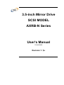
3.5-inch Mirror Drive
SCSI MODEL
AXRB-N Series
User's Manual
P/N A202985
Revision 1.1e
偶数ページで終了するための白紙です
3.5-inch Mirror Drive SCSI Model User's Manual
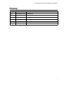
History
Revision
Date
Change
1.0e
25 September,2002
Initial release.
i
Storage Vision Co.,Ltd.
Introduction
Thank you for selecting the 3.5-inch Mirror Drive SCSI Model AXRB-N Series. This manual
describes how to install, operate, and maintain your Mirror Drive, and will help familiarize you with
the Mirror Drive and its features.
NOTICE
Please be sure to read the user's manual before using your Mirror Drive.
This manual provides information on and describes appropriate handling procedures and
configurations for all product functions. This information will allow the user to take full advantage of
the 3.5-inch Mirror Drive SCSI Model AXRB-N Series.
In the unlikely event you experience problems, the manual provides helpful information and
instructions.
RETAINING PACKAGING MATERIALS
The original packaging materials protect the Mirror Drive from damage during transportation.
After unpacking the Mirror Drive, please retain the packaging materials in case you need to ship the
Drive for repairs.
This product is sealed in an antistatic and moisture-proof bag before shipping. Open the bag only
when about to begin setup.
RECORDING THE PRODUCT NAME, VERSION, AND SERIAL NUMBERS
Before installing the Mirror Drive on the host computer, please jot down the model name, version,
and serial numbers.
Section "2.1 Part Names" shows the label location of model name, version, and serial number.
●
THIS DOCUMENT MAY NOT BE REPRODUCED OR COPIED IN WHOLE OR IN PART.
●
THE CONTENTS OF THIS DOCUMENT ARE SUBJECT TO CHANGE WITHOUT NOTICE.
●
WE HAVE MADE EVERY EFFORT TO ENSURE THE ACCURACY AND COMPLETENESS
OF THIS DOCUMENT. IF YOU FIND INACCURACIES OR OMISSIONS, PLEASE CONTACT
YOUR DISTRIBUTOR.
Copyright(c)
ii
Storage Vision Co., Ltd
All rights reserved.
3.5-inch Mirror Drive SCSI Model User's Manual
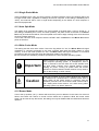
To ensure safe use of this product:
This user's manual uses the following symbols to highlight important points related to safe use of this
product. Please observe all safety information indicated in this way.
SAFETY SYMBOLS
To protect against personal injury and product damage, the following symbols are used throughout
this manual to highlight safety information.
Warning
Indicates a potentially hazardous situation that may result in
death or serious injury to the user or severe damage to the
product.
Caution
Indicates a potentially hazardous situation that may result in
serious injury to the user or damage to the product.
Important
Indicates important information, failure to observe which may
result in improper product function.
WARNING / CAUTION LABELS
Labels with black lettering against a yellow background affixed either to the exterior or interior of the
product are Warning or Caution labels that provide important safety information. Observe all
directions given on these labels.
In the case of appearing Warning or Caution labels in addition to this user's manual, be sure to
follow the directions on it.
iii
Storage Vision Co.,Ltd.
Warning
y If you detect any abnormal conditions, such as smoke or foul odors, immediately shut off power for
the host computer.
y If any foreign materials (metals, water, liquids, etc.) enter the Mirror Drive, immediately shut off
power for the host computer.
y Do not use the Mirror Drive in hot or damp locations. Doing so may result in fire, electrical shock,
or damage.
y Do not disassemble or modify this product. ADTX cannot guarantee the performance or safety of
any product that has been repaired by the customer or by an unauthorized third party. Doing so
may result in fire, electrical shock, or damage.
y Before connecting or disconnecting the interface connector, shut off power for the host computer
and any connected devices. To avoid placing excessive stress on the printed circuit board of the
Mirror Drive, push or pull the connector only along the axis perpendicular to the board. Avoid
bending the connectors. Avoid using undue force to connect or disconnect connectors or cables.
Doing so may result in fire, electrical shock, or damage.
iv
3.5-inch Mirror Drive SCSI Model User's Manual
Caution
y Do not use the Mirror Drive in locations subject to vibration or shock exceeding the specified
values. Use of the Mirror Drive in such locations may result in malfunctions or disk failure.
y Do not use the Mirror Drive in locations or circumstances subject to condensation. Rapid
temperature changes may cause condensation to form on the Mirror Drive itself. If you believe
condensation has occurred, leave the Mirror Drive to acclimate to the new environment. Avoid
using the Mirror Drive until it reaches the new ambient temperature.
y Do not place the Mirror Drive near electronic components with strong electromagnetic fields, such
as televisions or loudspeakers.
Use of the Mirror Drive in such locations may result in malfunctions or disk failure.
y Turn power off before moving the unit with the Mirror Drive. This will prevent damage to the HDD
and other internal components of the Mirror Drive.
y Do not turn power on immediately after turning power off, or turn power off immediately after
turning power on. Leave at least 20 seconds between successive operations involving powering
on or off. This will help prevent damage to or malfunction of the mounted HDD. The HDD motor
spindle requires about 20 seconds to stop rotating and come to a full rest. In addition, if removing
the correctly functioning drive unit drive unit for replacement, turn power off and wait at least 20
seconds.
y Do not remove the correctly functioning drive unit while power is on. The Mirror Drive will detect it
failed if the drive unit is removed. Doing so may damage the disk heads and platter inside the
HDD.
y Do not leave the Mirror Drive unpacked and unused for long periods of time (at most three
months). Doing so may lead to malfunctions or disk failure.
y Avoid applying excessive pressure to the covers of the drive unit. Doing so may lead to
malfunctions or disk failure.
y After unpacking or moving the Mirror Drive, gently press the front panel of the drive units to
confirm that they are properly inserted.
v
Storage Vision Co.,Ltd.
Important
y Back up all important data stored on the Mirror Drive to a suitable storage medium, such as tape
drive or MO drive. This product's mirroring technology prevents data loss even if one drive unit
fails. If two drives units fail at the same time or if a non-redundant part fails, data loss may still
occur. Additionally, accidental deletion of data or equipment damage may also result in data loss.
y Do not block the ventilation openings. Doing so may lead to hard disk drive failure.
y Wait at least 10 seconds after the drive access indicator has stopped flashing before initiating the
shutdown procedure for your host computer. The Mirror Drive uses cache memory to store data
frequently accessed from the HDD. Except in emergencies, you must follow the operating
system's shutdown procedures. Failure to so may result in loss of data stored in cache memory.
y Never remove or exchange the drive units, except to replace controller units or drive units, since
the Mirror Drive controls drive units by using its serial number. Thus, removal or replacement
may result in failure to boot up the host computer.
y When installing it in the host computer's bay, mount the Mirror Drive securely using the mounting
screws provided (recommended torque 0.49 Nm).
y In the event of a drive unit failure, it may take up to 25 seconds to start up the Mirror Drive. The
host computer may yet fail to recognize due to BIOS timeout settings.
vi
3.5-inch Mirror Drive SCSI Model User's Manual
Handling Static-Sensitive Devices
To prevent damage to components from static electricity, observe the following precautions when
handling this product.
y Before handling the Mirror Drive or other static-sensitive devices, touch a metal object, such as
the metal enclosure of the host computer, to discharge any static electricity from your body.
y Always handle components carefully. Never touch exposed circuitry.
y When replacing controller units or drive units, or when moving the Mirror Drive, place the
antistatic bag in which this product was shipped on a flat, level surface. Work on the Mirror Drive
in this area.
vii
Storage Vision Co.,Ltd.
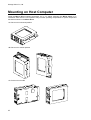
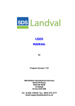
Mounting on Host Computer
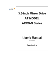
Install the Mirror Drive oriented horizontally, as in <A> below. Mounting the Mirror Drive in an
orientation other than the one specified may increase operating temperatures or place unexpected
mechanical stress on the Mirror Drive.
<A> Drive unit in horizontal position
<B> Drive unit in vertical position
<C> Drive unit on its side
viii
3.5-inch Mirror Drive SCSI Model User's Manual
[Contents]
History ............................................................................ i
introduction
....................................................................... ii
To ensure safe use of this product: ................................................... iii
warning ...........................................................................iv
Caution
........................................................................... v
Important ..........................................................................vi
Handling Static-Sensitive Devices ................................................... vii
Mounting on Host Computer ........................................................ viii
Contents ......................................................................... ix
1. Introducing the 3.5-inch Mirror Drive ................................................ 1
1.1 Features ........................................................................ 1
1.2 Mirroring ........................................................................ 2
1.3 Cache Buffer Function ............................................................ 2
2. External Dimensions .............................................................. 3
2.1 Part Names ..................................................................... 3
2.2 Front View (With Bezel Open) ...................................................... 4
2.3 Front View (With Bezel Closed) ..................................................... 4
2.4 External Dimensions .............................................................. 5
2.4.1 Mirror Drive ................................................................. 5
2.4.2 External Dimensions with 5-inch Bay attached
.................................... 6
3. Mounting in the Host Computer .................................................... 7
3.1 DIP Switch Settings ............................................................... 7
3.2 Mounting in the Host Computer ..................................................... 7
3.3 Connecting Cables ............................................................... 8
3.4 Turning on Main Power ............................................................ 8
4. Settings ......................................................................... 9
4.1 Configuration DIP Switch 1 ......................................................... 9
4.1.1 SCSI ID ................................................................... 10
4.1.2 Single Ended Mode .......................................................... 11
4.1.3 Auto Spin Mode ............................................................. 11
4.1.4 Write Cache Mode .......................................................... 11
4.1.5 Buzzer Mode ............................................................... 11
4.2 Configuration DIP Switch 2 ........................................................ 12
5. Status Display .................................................................. 13
ix
Storage Vision Co.,Ltd.
5.1 Indicator ....................................................................... 13
5.1.1 Access Indicator ............................................................ 13
5.1.2 Drive Status Indicator ........................................................ 13
5.1.3 Buzzer .................................................................... 14
5.2 External Output Signal ........................................................... 15
5.2.1 Status Output Signal ......................................................... 15
5.2.2 External LED Output Signal ................................................... 15
6. Removal and Replacement ....................................................... 16
6.1 Troubleshooting ................................................................. 16
6.2 Replacing Drive Units ............................................................ 17
6.2.1 Replacing a Drive Unit ....................................................... 17
6.2.2 Replacing Both Drive Units ................................................... 22
6.3 Replacing the Controller Unit ...................................................... 25
6.3.1 Replacing the Controller Unit (with both drives functioning normally)
................. 26
6.3.2 Replacing the Controller Unit (when one drive fails) ............................... 28
6.4 Other problems ................................................................. 32
6.5 Data Rebuilding ................................................................. 32
Appendix A
Specifications ........................................................ 33
A.1 Product Specification ............................................................ 33
A.2 External Output Signal Specifications ............................................... 34
A.2.1 Status Output Signal
........................................................ 34
A.2.2 External LED Output Signal ................................................... 36
Appendix B
Accessories .......................................................... 38
Appendix C
Factory default setting ................................................. 39
Appendix D
Replacement Parts .................................................... 40
Information ....................................................................... 41
x
3.5-inch Mirror Drive SCSI Model User's Manual
1. Introducing the 3.5-inch Mirror Drive
Incorporating two 2.5-inch disk drives, the ADTX 3.5-inch Mirror Drive uses mirroring technology to
safeguard data and to provide uninterrupted operations.
Since the host computer will recognize the Mirror Drive as a standard SCSI HDD, installing the
Mirror Drive simply involves connecting it to a SCSI cable from the host computer.
1.1 Features
y In the event that one of the drive units fails, the Mirror Drive will continue to function, maintaining
data integrity. When the failed disk is replaced with a new replacement disk, data rebuilding will
begin automatically.
y The Mirror Drive is provided with large cache memory capacity for high performance.
y Based on the industry standard SCSI-3 interface, the Mirror Drive can be used like any other
standard SCSI HDD. This product requires no unique device drivers and is compatible with most
operating systems. Moreover, it will be easily daisy-chained to a series of existing SCSI HDDs or
devices.
y Mirroring technology implemented via hardware reduces system overhead.
1
Storage Vision Co.,Ltd.
1.2 Mirroring
Mirroring technology involves writing data to two drive units simultaneously. If one drive unit fails, data
is written to and read from the other drive unit.
1.3 Cache Buffer Function
The Mirror Drive is equipped with large cache memory capacity. With write cache mode enabled, the
Mirror Drive will signal completion of command processing to the host computer when data is written
to cache memory. The performance will be improved by writing accumulated data to the HDD while
the host computer does not access to the Mirror Drive. Write cache mode is enabled via Switch 1.
The default setting at shipment is ON (enabled).
Important
2
Always observe the shutdown procedure specified for the
host computer operating system. In emergencies, wait at
least 10 seconds to be sure both the drive access indicator
and the drive status indicator have stopped flashing before
shutting off power. Turning off power while the access
indicator or the drive status indicator is on may result in loss
of data still residing in cache memory.
3.5-inch Mirror Drive SCSI Model User's Manual
2. External Dimensions
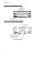
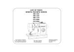
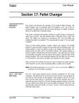
2.1 Part Names
Status Bit connector
(For details, refer to "A.2.1 Status Bit connector")
Power connector
SCSI connector
MODEL:AXRB-N102S
EC:YBxxxx
S/N:BX00001
Model name
Version
Serial number
Controller unit
Bezel
External LED connector
(For details, refer to "A.2.2 External LED connector")
3
Storage Vision Co.,Ltd.
2.2 Front View (With Bezel Open)
Drive lever
Drive unit 1
Drive unit 2
DIP switch 1
2.3 Front View (With Bezel Closed)
Bezel lock
Power indicator
Access indicator
Drive status indicator
4
3.5-inch Mirror Drive SCSI Model User's Manual
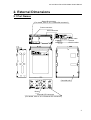
2.4 External Dimensions
2.4.1 Mirror Drive
Mounting screw holes
3-#6-32UNC(x3)
Same on opposite side
18.9
63.3
60
133.3
148.7
44.5
41.6
Mounting screw holes
4-#6-32UNC(x4)
6.4
42
101.6
3.2
95.2
3.2
5
Storage Vision Co.,Ltd.
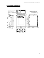
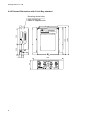
2.4.2 External Dimensions with 5-inch Bay attached
Mounting screw holes
4-#6-32UNC(x4)
Same on opposite side
MODEL:AXRB-N102S
EC:YBxxxx
S/N:BX00001
52.5
9.9
11.9
43
146
6
148.7
140
79.2
MADE IN JAPAN
3.5-inch Mirror Drive SCSI Model User's Manual
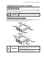
3. Mounting in the Host Computer
3.1 DIP Switch Settings
Before mounting it in your host computer, check to confirm the DIP switch settings for the Mirror
Drive. Refer to "4. Settings" for the correct configurations of the DIP switches. For default settings,
refer to "Appendix C Factory Default Settings."
Caution
Before setting any DIP switches or connecting cables, make
sure the power supply of the host computer has been turned
off.
3.2 Mounting in the Host Computer
When mounting in the host computer, use the attached mounting screws and the specified mounting
holes. The mounting screw hole locations are shown in "2.4 External Dimensions."
An example of a mounting screw hole location is shown below.
Caution
When installing into the host computer, provide sufficient
cooling in order to ensure that the surface temperature of the
drive unit remains below 60°C.
Do not block the ventilation openings. Without proper
ventilation, the Mirror Drive will malfunction or fail.
7
Storage Vision Co.,Ltd.
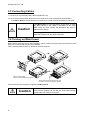
3.3 Connecting Cables
<1> Connect a 4-pin internal power cable, supplied DC +5V.
<2> Connect an internal SCSI cable to the host computer or to other existing SCSI peripherals.
If the Mirror Drive is the last device in the SCSI chain, install the SCSI terminator to the cable.
Caution
If the Mirror Drive is of the last device in the chain or is the
only SCSI device in use, attach a terminator to the SCSI
cable. Using the drive without the terminator will result in
malfunctions or failure.
We strongly recommend using the shortest possible SCSI
cable that complies with the SCSI-3 standard.
3.4 Turning on Main Power
Before turning on power for the host computer, open the bezel lock and press the front face of each
drive unit to confirm that they are firmly inserted.
Then, close the bezel and turn on power for the host computer.
Close to lock the bezel.
Confirm that the bezel is firmly locked.
Gently press front panel of the drive units
to confirm that they are properly inserted.
Confirm that the host computer recognizes the Mirror Drive.
Caution
8
Before turning on power for the host computer, confirm that
SCSI IDs are properly set and that the SCSI cable and the
power cable are correctly connected.
3.5-inch Mirror Drive SCSI Model User's Manual
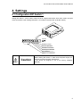
4. Settings
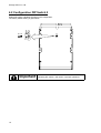
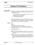
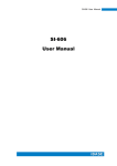
4.1 Configuration DIP Switch 1
Setting DIP switch 1 can be used to select SCSI ID, single ended mode, write cache mode, auto spin
mode and buzzer mode. Setting DIP switch 1 is located in the lower left. (8-bit DIP switch).
ON OFF
1
2
3
4
5
6
7
8
SW8:Buzzer Mode
SW7:Auto Spin Mode
SW6:Write Cache Mode
SW5:Single Ended Mode
SW1-4:SCSI ID
(Refer to "4.1.1 SCSI ID".)
Caution
Before setting DIP switch 1, make sure the power supply for
the host computer has been switched off.
(The above the diagram is set to the factory shipping
defaults.)
9
Storage Vision Co.,Ltd.
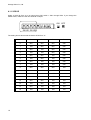
4.1.1 SCSI ID
Select a SCSI ID (from 0 to 15) using binary DIP switch 1 SW1 through SW5. If you change the
default value, make sure the new SCSI ID is unique.
ON OFF
1 2 3 4 5
ID0 ID1 ID2 ID3
6
7
8
The setting shown above sets the device SCSI ID to "0."
10
SCSI ID
ID0
ID1
ID2
ID3
0
OFF
OFF
OFF
OFF
1
ON
OFF
OFF
OFF
2
OFF
ON
OFF
OFF
3
ON
ON
OFF
OFF
4
OFF
OFF
ON
OFF
5
ON
OFF
ON
OFF
6
OFF
ON
ON
OFF
7
ON
ON
ON
OFF
8
OFF
OFF
OFF
ON
9
ON
OFF
OFF
ON
10
OFF
ON
OFF
ON
11
ON
ON
OFF
ON
12
OFF
OFF
ON
ON
13
ON
OFF
ON
ON
14
OFF
ON
ON
ON
15
ON
ON
ON
ON
3.5-inch Mirror Drive SCSI Model User's Manual
4.1.2 Single Ended Mode
If this is enabled (set to "ON," the down position), the SCSI interface of the host computer will be set
to single ended mode, regardless of settings at the host computer. If this setting is disabled (set to
"OFF"), the mode set will be LVD or single ended, depending on the status of a host computer or
other SCSI peripherals.
4.1.3 Auto Spin Mode
This setting is for automatically rotating the motor spindle of the HDD when power is turned on . If
this setting is disabled (set to "OFF," the down position), the peak current at the start of the Mirror
Drive may be reduced somewhat, since the spindle motor will not begin rotating at the same time that
the host computer starts up.
In this case, have the host computer issue the START UNIT COMMAND to the Mirror Drive when
power is turned on.
4.1.4 Write Cache Mode
This setting sets the write cache mode. If set to the Up position for "On," the Mirror Drive will signal
completion of command processing to the host computer when data has been written to cache
memory. If set to the Down position for "Off," the Mirror Drive will signal completion of command
processing to the host computer when data has been written to the drive unit.
Be sure to follow the shutdown procedure specified for the host computer operating system.
Important
Always observe the shutdown procedure specified for the
host computer operating system. In emergencies, wait at
least 10 seconds to be sure both the access indicator and
the drive status indicator have stopped flashing before
shutting off power. Turning off power while the access
indicator or the drive status indicator remains lit may result in
loss of data residing in cache memory.
Caution
If the host computer is running either Windows 95, Windows
98, Windows NT, Windows Me or Windows 2000, both of
which switch off the power supply in synchrony with the
shutdown procedure, be sure to set the write cache mode to
"Off." Setting write cache mode to "On" while running either
operating system may lead to data loss.
4.1.5 Buzzer Mode
If set to the Up position ("On"), a buzzer will sound if any error is detected. In the event of a drive unit
failure, the buzzer will continue to sound until the failed unit is replaced. While the buzzer mode
switch can be used to stop the buzzer, the setting can only be disabled after the failed drive has been
replaced.
11
Storage Vision Co.,Ltd.
4.2 Configuration DIP Switch 2
Setting DIP switch 2 disables changes in the configuration.
The factory default setting is given below.
32
O
N
O
N
O
N
O
N
32
OFF ON
Important
12
Resetting DIP switch 2 will result in improper operations.
3.5-inch Mirror Drive SCSI Model User's Manual
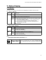
5. Status Display
5.1 Indicator
The status of the controller unit and drive units is displayed by the indicator on the front cover.
5.1.1 Access Indicator
Power
Green
Power is on.
Access
Green
Normal operation.
Orange
An error has occurred in the controller unit.
Orange
flashing
<1> Both drive units have failed, or the drives may not be properly inserted
(if both status indicators are out ).
<2> The user has mistakenly replaced the correctly operating drive unit,
not the one that has failed (if both status indicators are out).
<3> Data rebuilding is in operation (with copy to the target drive unit
indicated by the green light).
Any of the above.
5.1.2 Drive Status Indicator
Drive
unit 1
Drive
unit 2
Green
Data rebuilding copied to drive unit 1 is operation. (1)
Orange
<1> Drive unit 1 has failed.
<2> Drive unit 1 has reset. (2)
Green
Data rebuilding copied to drive unit 2 is operation. (1)
Orange
<1> Drive unit 2 has failed.
<2> Drive unit 2 has reset. (2)
Note:
(1) Drive Status Indicator will go out after data rebuilding.
(2) In the event of reset, the buzzer will not beep.
Important
If the drive status indicator flashes orange, immediately
replace the specified drive unit. Leaving the Mirror Drive
with a failed drive will result in data loss if the other drive
fails.
13
Storage Vision Co.,Ltd.
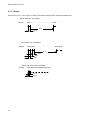
5.1.3 Buzzer
If this is set to "On," in the event of a failure, the buzzer will beep at the interval specified below.
When drive unit 1 has failed
Buzzer
beep ................................................ beep ............
3.2s
0.3s
When drive unit 2 has failed
Buzzer
beep,beep ............................................ beep,beep ...
3.1s
0.3s
0.3s
0.3s
When both drive units have failed
Buzzer
beep,beep,beep,beep,beep,beep ...
0.1s
0.1s
14
3.5-inch Mirror Drive SCSI Model User's Manual
5.2 External Output Signal
The output signal can be transmitted to monitor the detected status externally. The Mirror Drive has
two types of signals; a status output signal and an external LED output signal. The connectors for
these signals are shown in the figure below.
External LED connector
Status Bit connector
5.2.1 Status Output Signal
Status output is transmitted as a 3-bit signal.
For detail layouts and electrical specifications for the status bit connector pins, refer to "Appendix
A.2.1 Status Output Signal."
5.2.2 External LED Output Signal
The drive status indicators of the Mirror Drive, green and orange signals for each drive, can be
monitored externally in the same manner. These connections and settings will permit transmission of
these signals to remote LEDs. For detail layouts and electrical specifications for the external LED
connector pins, refer to "Appendix A.2.2 External LED Output Signal."
15
Storage Vision Co.,Ltd.
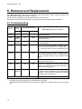
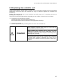
6. Removal and Replacement
If the Mirror Drive fails, the access indicator will light continuously or flash orange, while the drive
status indicator will light continuously in orange.
If buzzer mode is enabled, the buzzer will continue to sound an alert.
Determination of removal and replacement must account for these status/failure indications.
6.1 Troubleshooting
Power
indicator
Access
indicator
Drive status indicator
Mirror Drive status and measures.
Drive unit 1
Drive unit 2
Green
---
---
---
Green
Orange
flashing
Off
Green
Rebuilding data from drive unit 1 to drive unit 2.
(normal operation)
Green
Orange
flashing
Green
Off
Rebuilding data from drive unit 2 to drive unit 1.
(normal operation)
Green
---
Green
---
To confirm the connect status of device unit 1,
remove and reinsert drive unit 1 while power is
on. If recovery does not occur, replace drive unit
1.
Green
---
---
Green
To confirm the connect status of device unit 2,
remove and reinsert drive unit 2 while the power
is on. If recovery does not occur, replace drive
unit 2.
Green
Orange
---
---
Controller unit failure. Replace the controller unit
with a new controller unit.
Off
Off
Off
Off
Check the condition from of the power supply
status. If not recovered, replace the controller unit
with a new controller unit.
Green
Orange
flashing
Off
Off
Check the condition of both drive units and check
to confirm that the desired drive unit was properly
replaced. If not recovered, replace the controller
unit with a new controller unit.
Other lit or flashing indicator.
Normal operations.
Contact your distributor.
---:Normally off, or light continuously, or flashing when accessed.
If replacing the drive unit does not fix the problem, replace the controller unit with a new controller
unit.
16
3.5-inch Mirror Drive SCSI Model User's Manual
6.2 Replacing Drive Units
If one of the drive units fails, the Mirror Drive will continue to function, maintaining data integrity
without requiring you to reboot your host computer. When the failed drive unit is replaced with a new
drive unit, data rebuilding will begin automatically.
When replacing a drive unit, check to be sure that the drive status indicator lights in orange.
Important
Before replacing the failed drive unit, be sure to prepare the
drive unit designated by ADTX as described in "Appendix D
Replacement Parts. ". Do not replace with HDDs other than
the designated model, even if the capacity, manufacturer, or
model numbers on the label are same. Doing so will result in
malfunction or damage. The warranty does not cover any
damages resulting from replacement with non-specified
HDD, and ADTX will not be liable for any consequences of
doing so.
If the drive status indicator light in orange, immediately
replace the specified drive unit with a new drive unit. Leaving
the Mirror Drive with a single operating drive unit will result
in data loss if the other drive unit fails.
Caution
Before handling the controller unit or drive unit while
replacing the drive unit, touch a metal object, such as the
metal enclosure of the host computer, to discharge static
electricity from your body.
Avoid subjecting the drive unit or controller unit to vibrations
or shock when replacing. Subjecting the drive unit or
controller unit to vibration or shock may result in malfunction
or failure.
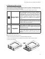
6.2.1 Replacing a Drive Unit
● Replacement Procedure (with power on)
1. Prepare the new drive unit specified in "Appendix D Replacement Parts.".
2. Confirm correct identification of the failed drive unit by the drive status indicator or buzzer.
3. Unlock to open the bezel.
17
Storage Vision Co.,Ltd.
4. Pull the levers on the failed drive unit with your hands, then carefully remove the drive unit from the
Mirror Drive.
5. After closing the levers on the new drive unit, slide it firmly to the backplane with your hands.
6. Close to lock the bezel. Confirm that the bezel is firmly locked.
18
3.5-inch Mirror Drive SCSI Model User's Manual
7. In seconds, data rebuilding will start, while the drive status indicator for the replaced drive unit
lights in green and the indicator for the correctly functioning drive unit remains unlit. The access
indicator for the replaced drive unit will flash in orange.
Important
Do not remove the drive unit while rebuilding data.
8. When data rebuilding is complete, the drive status indicator will go out.
9. If the drive status indicator for the replaced drive unit does not turn green or turns orange once
again, repeat the procedure, starting with step 2.
Important
If you mistakenly replace the correctly functioning drive unit,
the drive status indicator for both drive units will go out while
the access indicator will flash orange. The host computer will
be unable to operate the Mirror Drive.
In this case, turn off the host computer. Replace the failed
drive unit with the new drive unit, and replace the correctly
functioning drive unit. Turning on the host computer will begin
data rebuilding.
19
Storage Vision Co.,Ltd.
● Replacement Procedure (with power off)
1. Prepare the new drive unit specified in "Appendix D Replacement Parts.".
2. Confirm the identify of the failed drive unit by the drive status indicator or buzzer.
3. Turn off the host computer.
4. Unlock to open the bezel.
5. Pull the levers on the failed drive unit with your hands, then carefully remove the drive unit from the
Mirror Drive.
6. After closing the levers on the new drive unit, slide it firmly to the backplane with your hands.
20
3.5-inch Mirror Drive SCSI Model User's Manual
7. Close to lock the bezel. Confirm that the bezel is firmly locked.
8. Turn on the host computer.
9. In seconds, data rebuilding will start, while the drive status indicator for the replaced drive unit will
light continuously in green. The indicator for the correctly functioning drive unit will not light. The
access indicator for the replaced drive unit will flash orange.
Important
Do not remove the drive unit while data is rebuilding.
10. When data rebuilding is complete, the drive status indicator will go out.
11. If the drive status indicator for the replaced drive unit does not turn green or turns orange once
again, repeat the procedure, starting with step 2.
Important
If you mistakenly replace the correctly functioning drive unit,
the drive status indicator for both drives will go out, and the
access indicator will flash in orange. The host computer will
be unable to operate the Mirror Drive.
In this case, turn off the host computer. Replace the failed
drive with a new drive and reinstall the correctly functioning
drive unit. Turning on the host computer will begin data
rebuilding.
21
Storage Vision Co.,Ltd.
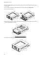
6.2.2 Replacing Both Drive Units
Important
Because this is an emergency recovery procedure, data
corruption may occur.
To avoid further data loss, back up all important data stored
on the Mirror Drive to a suitable storage medium, such as
tape drive or MO drive.
1. Prepare the new drive unit specified in "Appendix D Replacement Parts.".
2. Turn off the host computer.
3. Unlock to open the bezel.
4. Pull the levers on the failed drive unit with your hands, then carefully remove the drive unit from the
Mirror Drive.
(E.g.) When drive unit 1 failed first
5. Turn on the host computer.
6. Confirm that the host computer recognizes the Mirror Drive.
22
3.5-inch Mirror Drive SCSI Model User's Manual
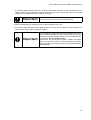
7. After confirming that the host computer recognizes the Mirror Drive, After closing the levers on the
new drive unit, slide it firmly to the backplane with your hands.
8. In seconds, data rebuilding will start, while the drive status indicator for the replaced drive unit will
light continuously in green. The indicator for the correctly functioning drive unit will not light. The
access indicator for the replaced drive unit will flash orange.
Important
Do not remove the drive unit while data is rebuilding.
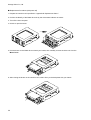
9. When data rebuilding is complete, the drive status indicator will go out. Turn off the host computer.
10. Pull the levers on the failed other drive unit with your hands, then carefully remove the drive unit
from the Mirror Drive.
(E.g.) When drive unit 2 was the next to fail
23
Storage Vision Co.,Ltd.
11. After closing the levers on the new drive unit, slide it firmly to the backplane with your hands.
12. Close to lock the bezel. Confirm that the bezel is firmly locked.
13. Turn on the host computer.
14. In seconds, data rebuilding will start, while the drive status indicator for the replaced drive unit will
light continuously in green. The indicator for the correctly functioning drive unit will not light. The
access indicator for the replaced drive unit will flash orange.
Important
Do not remove the drive unit while data is rebuilding.
15. When data rebuilding is complete, the drive status indicator will go out.
16. If the drive status indicator for the replaced drive unit does not turn green or turns orange once
again, repeat the procedure, starting with step 2.
24
3.5-inch Mirror Drive SCSI Model User's Manual
6.3 Replacing the controller unit
If the access indicator remains light in orange, or the drive status indicator light orange despite
replacement of the drive unit, the controller unit may be defective. Replace the controller unit
immediately.
Replace the controller unit with a new controller unit while power is off. Controller units are not
hot-swappable components.
There are two replacement procedures, depending on the condition of the drive unit, as follows:
<1> If both drive units are function normally:
Transfer both drive units to the new controller unit.
Ensure that each drive unit is inserted into the appropriate drive bays.
<2> If one drive unit fails:
Transfer only the correctly functioning drive unit to the new controller unit.
Before replacing controller units, check to confirm that the
host computer has been turned off.
Caution
Before handling the controller unit or drive unit while
replacing the controller unit, touch a metal object, such as
the metal enclosure of the host computer, to discharge static
electricity from your body.
Avoid subjecting the drive unit or controller unit to vibrations
or shock when replacing. Subjecting the drive unit or
controller unit to vibration or shock may result in malfunction
or failure.
25
Storage Vision Co.,Ltd.
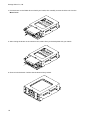
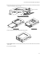
6.3.1 Replacing the Controller Unit (with both drives functioning normally)
● Replacement Procedure
1. Prepare the new controller unit specified in "Appendix D Replacement Parts.".
2. Turn off the host computer.
3. Disconnect the SCSI cable and 4-pin internal power cable and remove the Mirror Drive from the
host computer.
Caution
When replacing controller units, place the antistatic bag in
which this product was originally packed on a flat, level
surface. Work on the Mirror Drive in this area.
4. Unlock to open the bezel.
5. Pull the levers on the drive unit with your hands, then carefully remove each drive unit from the
Mirror Drive.
26
3.5-inch Mirror Drive SCSI Model User's Manual
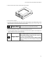
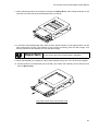
6. After closing the levers on the drive unit, insert the drive unit into the same numbered bay and slide
it firmly to the backplane using your hands.
1
Drive unit number
2
Drive unit number display location
Insert drive unit 2 Insert drive unit 1
7. Close to lock the bezel. Confirm that the bezel is firmly locked.
8. Mount the Mirror Drive in the host computer and firmly connect the SCSI cable and 4-pin internal
power cable.
9. Turn on the host computer.
27
Storage Vision Co.,Ltd.
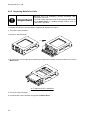
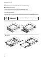
6.3.2 Replacing the Controller Unit (when one drive fails)
● Unit Replacement Procedure
1. Prepare the new controller unit in "Appendix D Replacement Parts.".
2. Confirm the identity of the failed drive unit by the drive status indicator or buzzer.
3. Turn off the host computer.
4. Disconnect the SCSI cable and 4-pin internal power cable and remove the Mirror Drive from the
host computer.
Caution
When replacing controller units, place the antistatic bag in
which this product was originally packed on a flat, level
surface. Work on the Mirror Drive in this area.
5. Unlock to open the bezel.
6. Pull the levers on the drive unit with your hands, then carefully remove each drive unit from the
Mirror Drive.
28
3.5-inch Mirror Drive SCSI Model User's Manual
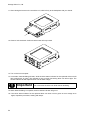
7. After closing the levers on the drive unit, insert the correctly functioning drive unit into the same
numbered bay and slide it firmly to the backplane with your hands.
1
Drive unit number
2
Drive unit number display location
(E.g.) When drive unit 2 is operating normally
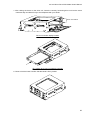
8. Close to lock the bezel. Confirm that the bezel is firmly locked.
29
Storage Vision Co.,Ltd.
9. Mount the Mirror Drive in the host computer. Firmly connect the SCSI cable and 4-pin internal
power cable.
10. Turn on the host computer. Confirm that the host computer recognizes the Mirror Drive.
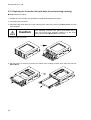
11. Unlock to open the bezel.
12. After closing the levers on the drive unit, insert the new drive unit into the desired bay and slide it
firmly to the backplane with hands.
(E.g.) When replacing drive unit 1.
13. Close to lock the bezel. Confirm that the bezel is firmly locked.
30
3.5-inch Mirror Drive SCSI Model User's Manual
14. In seconds, data rebuilding will start while the drive status indicator for the replaced drive unit will
light in green and the indicator for the correctly functioning drive unit goes out. The access
indicator for the replaced drive unit will flash in orange.
Important
Do not remove the drive unit while data is rebuilding.
15. When data rebuilding is complete, the drive status indicator will go out.
16. If the drive status indicator for the replaced drive unit does not turn green or lights in orange once
again, reinsert both drive units.
31
Storage Vision Co.,Ltd.
6.4 Other problems
If the problem persists even after you replace the drive unit or the controller unit, please contact your
distributor.
6.5 Data Rebuilding
If a drive unit that has failed was correctly replaced, data rebuilding (the copying of all data on the
primary drive to the replaced new drive unit) will start automatically.
If one of the drive units fails, the Mirror Drive will continue to function, maintaining data integrity.
During data rebuilding, the drive status indicator for the correctly functioning drive unit will go out, and
the drive status indicator for the replaced drive unit will light in green.
Caution
Do not turn off the host computer while the Mirror Drive is
rebuilding data. Doing so may result in loss of data or failure.
If, during data rebuilding, there are sectors that cannot be read on the normally operating drive unit,
data rebuilding will skip these sectors and continue. These skipped sectors will no longer be
readable. However, if new data is written to those sectors, those sectors will become readable.
Important
32
If the data recovery process skips errors during data
rebuilding, then the data on those sectors will be lost.
It is recommended you make periodic backups.
3.5-inch Mirror Drive SCSI Model User's Manual
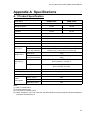
Appendix A Specifications
A. 1 Product Specification
Model Name
AXRB-N102S
RAID levels
AXRB-N202S
1
Storage Capacity
LBA
Cylinders
10 GB
20 GB
19,636,736
39,065,984
19,480
38,755
Heads
16
Sectors
63
Host interface
Ultra Wide SCSI (LVD or SE)
Data transfer speed (max.)
Number of HDDs
External
Dimensions
Weight (max.)
Operational
environment
(1)
2
Mirror Drive
101.6mm (W) x 148.7mm (L) x 42.0mm (H)
Mirror Drive with
5-inch bay attached
146.0mm (W) x 148.7mm (L) x 43.0mm (H)
Mirror Drive
700g
Mirror Drive with
I5-inch bay attached
900g
Temperature
Humidity
Voltage (Vcc)
In operation 5 to 45 °C (4)
Not in operation -40 to 65 °C
In operation 8 to 90%
Not in operation 5 to 95%
4.85 to 5.25 VDC
Power supply ripple (2) (max.)
Power startup time (3)
Power
consumption
40MB/s
100mV p-p (0 to 20 MHz)
5 to 100 ms
Startup (max.)
2.6A
Idle (max.)
1.3A
Read/Write (max.)
2.0A
Note:
(1): With no condensation.
(2): Including startup time.
(3): Time until Vcc reaches 4.85V.
(4): When mounting in your host computer, provide sufficient cooling to keep the surface temperature
of the drive unit below 60 °C.
33
Storage Vision Co.,Ltd.
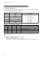
A.2 External Output Signal Specifications
A.2.1 Status Output Signal
This table shows the pin configurations, status definitions, internal circuitry, electrical specifications,
and connector specifications for the status output signal.
The connector signal pins are configured as follows:
Pin Number
Signal
Pin configuration
1
GND
2
+5VDC
3
Status bit 2
4
Status bit 1
5
Status bit 0
6
GND
5
6
3
4
1
2
Status output is transmitted in 3-bit signals, as follows:
Number
Status bit 2
Status bit 1
Status bit 0
0
1
2
3
4
5
6
7
L
L
L
L
H
H
H
H
L
L
H
H
L
L
H
H
L
H
L
H
L
H
L
H
Status
Normal operation
Drive unit 1 has failure
Drive unit 2 has failure
Data rebuilding
Controller unit failure (1)
Reserved
Mirror Drive startup processing
Initializing
H: TTL level output high.
L: TTL level output low.
Note:
(1) The following may indicate damage to the controller unit.
- If both drive units fail to power on.
- If both drive units are properly connected, with power on
- If the correctly functioning drive is erroneously replaced, rather than the drive unit that failed.
34
3.5-inch Mirror Drive SCSI Model User's Manual
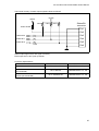
The internal circuitry of status output signals indicate as follows:
+5VDC
+5VDC
10K Ω
10K Ω
10K Ω
160mA FUSE
Status Bit
connector
Pin1
Pin2
Status bit 2
Pin3
Status bit 1
Pin4
Status bit 0
Pin5
LS07
Pin6
Status output signal uses LS07 (open corrector).
Each output has a 10K Ωpull-up resistor.
Connector Specifications
Mirror Drive header
External connectors – connector side
(recommended)
External connectors – connector crimp
contacts (recommended)
Part name
Manufacturer
DF11-6DP-2DSA
HIROSE Electric Co., Ltd.
DF11-6DS-2C
HIROSE Electric Co., Ltd.
DF11-2428SCF/SC
HIROSE Electric Co., Ltd.
35
Storage Vision Co.,Ltd.
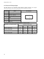
A.2.2 External LED Output Signal
This table shows the pin configuration, status definitions, external connection circuit diagram,
electrical specifications, and connector specifications for the external LED connector.
The connector signal pins are configured as follows:
Pin Number
Signal
1
Drive unit 1 green LED
2
GND
3
Drive unit 1 red LED
4
Drive unit 2 green LED
5
GND
6
Drive unit 2 red LED
7
Reserved
8
Reserved
Pin configuration
1
3
5
2
4
6
7
8
Output signals and drive status indicators Mirror Drive of correspond as below.
External LED output signal
Mirror Drive – Drive status indicators
Pin 1
Pin 3
Pin 4
Pin 6
Drive unit 1 green LED
On
Off
Off
Off
Drive unit 1 orange LED
On
On
Off
Off
Drive unit 2 green LED
Off
Off
On
Off
Drive unit 2 orange LED
Off
Off
On
On
36
3.5-inch Mirror Drive SCSI Model User's Manual
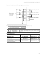
The internal circuitry of external LED output signal indicate as follows:
330 Ω
Pin 1
Drive unit 1 green LED
Pin 2
330 Ω
Pin 3
Drive unit 1 red LED
330 Ω
Pin 4
Drive unit 2 green LED
Source driver
ON: +5VDC
OFF: Open
Pin 5
330 Ω
Pin 6
Drive unit 2 red LED
Pin 7
Reserved
Pin 8
External LED output signal electrical specifications. (The signal pins 1, 3, 4, 6)
Source current (Output: High)
Caution
Max. 15mA
The output signal voltage will vary with internal control
resistance.
Connector specifications
Part name
Manufacturer
DF11-8DP-2DS22
HIROSE Electric Co., Ltd.
External connectors – connector side
(recommended)
DF11-8DS-2C
HIROSE Electric Co., Ltd.
External connectors – connector crimp
contacts (recommended)
DF11-2428SCF/SC
HIROSE Electric Co., Ltd.
Mirror Drive header
37
Storage Vision Co.,Ltd.
Appendix B Accessories
3.5-inch Mirror Drive SCSI Model AXRB-N Series is shipped with following accessories.
y 3.5-inch Mirror Drive SCSI Model AXRB-N Series user's manual. (This manual)
y Mounting screws. (x4)
38
3.5-inch Mirror Drive SCSI Model User's Manual
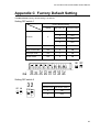
Appendix C Factory Default Setting
The Mirror Drive's factory default setting is as follows:
Setting DIP switch 1
Factory Default Setting
Setting
DIP Switch No.
DIP Switch setting
1
OFF
2
OFF
3
OFF
4
OFF
0
SCSI ID
Single ended mode
OFF
5
OFF
Write cache mode
ON
6
ON
Auto spin mode
ON
7
ON
Buzzer mode
ON
8
ON
ON OFF
ON
2
3
4
5
6
7
8
D0
D1
D2
D3
SE
CA
AS
BZ
1
Setting DIP switch 2
OFF ON
DIP Switch No.
DIP Switch setting
2
ON
3
OFF
O
N
O
N
32
Factory Default Setting
39
Storage Vision Co.,Ltd.
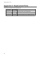
Appendix D Replacement Parts
The following are supplied as user-replaceable parts.
40
Part name
Part number
10GB drive unit
A202570
replacement drive unit for AXRB-N102S.
20GB drive unit
A202580
replacement drive unit for AXRB-N202S.
Controller unit
A202585
replacement controller unit for AXRB-N series SCSI.
3.5-inch Mirror Drive SCSI Model User's Manual
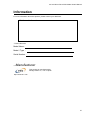
Information
For more information about this product, please contact your distributor.
Distributor's information
- Product Records
Model Name :
Model / Type :
Serial Number :
- Manufacturer
This product is manufactured by
Storage Vision Co., Ltd. in Japan.
http://www.str-v.com
41