1
le4 /Vete //frialeN
Here is a, new receiver for short-wave and amateur use-just the thing for the new "ham" or the old hand who wants
to build a new station. Special attention to layout and
design combine to make it close to the ideal in mediumsized sets. It works well on 10 metres, and provides continuous coverage to 100 metres. It may well be considered
our standard medium-sized short-waver for some time.
OW that amateur activity is well
N
under way, we decided to spend
some time answering an oft-repeated
for an ordinary dual-wave se-. Some
concession to shortwave performance
may be made in the latter. hu: the
economics of production and the requirements for domestic broadcast reception always remain the governing
factors.
question: "When will you describe a
set suitable for use on 10 metres? Mine
is OK on 20, but not so hot on higher
frequencies."
The time appears to be a good one
for the production of a standard, TUNING RATIOS
medium-sized set which would be good
For example, a large tuning confor 10 metres and above.
At the same time, a review of the denser gang is necessary to cover the
main design points concerning SW broadcast band, and this same consets in general seemed to be in order. denser is used for short waves. The
In this article, we have attempted to resultant shortwave band coverage is
broad enough to constitute a good
do both these things.
selling feature, , but the tuning from
station is necessarily very sharp.
GENERAL PROBLEMS
Stations .in the various International_
The problems involved in designing broadcast bands (likewise the amateur
and building a shortwave receiver are bands) are packed tightly together.
quite different from those which apply and the greatest care is necessary to
PARTS LIST
1 Chassis,
x 10in. x
1 Metal or, masonite panel I4in. x 91in.
2 180 degree nameplates ("Selector").
2 5-plate. midget cond. (35 mmfd.)
2 9-plate midget cond. (70 mmfd.)
3 Flexible condenser couplings.
I Vernier dial to suit.
2 465kc. Iron-cored I.F. trans.
I 80 or 100 mA. power trans.
2 Valve shields.
3 Potentiometers, 0-5 meg., 10,000
ohms, 2500 ohms.
13-position S.P. rotary switch.
I S.P.S.T. toggle switch.
I S.P.D.T. toggle switch.
5 Knobs, 2 pointer knobs.
1 Phone jack (or terminals).
1 25,000 ohm. voltage divider.
I 8 mfd. electrolytic cond. (600 P.V.).
I 16 mfd. electro. cond. (525 P.V.),
10 mfd. electro. cond. (40 P.V.)
4 0.1 mfd. tubular cond.
1 .05 mfd. tubular cond.
I .01 mfd. tubular cond.
1 .01 mfd. mica cond. (Osc. bypass).
I .00k mfd. mica cond.
PAGE EIGHTEEN
2 .00025 mfd. mica cond.
1 .0001 mfd. mica cond.
I .00005 mfd. mica cond.
I 1.0 meg. resistor.
1 .25 meg. resistor.
I 50,000 ohm. resistor.
1 20,000 ohm. resistor.
I 5000 ohm. resistor.
1 400 ohm, resistor (W.W.)
2 300 ohm. resistors (W.W.)
I 250 ohm. resistor (W.W.)
SPEAKER: To match single 6V6-G.
2000 ohm. field coil.
VALVES: I 6J8-G: 1 6U7-G; I 6J7-G;
16V6-G; 15Y3-G.
SOCKETS: 5 octal, I 4-pin. Also 2
sockets to suit plug-in coil formers.
SUNDRIES: Screws, nuts, washers
hook-up and shielded wire, spaghetti,
3 small grid clips. Three terminals
(2 red, I black) and mounting strip.
Pillars for coil socket and kin, dia.
rod for extension shafts. Coil
formers 1,1-f in. dia., two for each band.
Short length of din. dia. coil former.
Scrap aluminium or steel for mounting brackets &c. Winding wire as
specified in coil data.
by
n.
separate them. In any case, it is
most difficult to record their positions
on the dial for future reference.
When a receiver is designed for
operation only on the shortwave bands,
the need for a large tuning gang condenser—say .0004 mfd per section —
disappears. Instead, one can very conveniently tune the signal (and oscilawn circuits with variable condensers having no more than a small frac:ion of this capacitance—say .0001 mfd
or less.
By so doing, the frequency coverage
of the particular coil-condenser cornbtna:iDn is naturally reduced. Instead
of tuning from, say, 16 to 51 metres
in one sweep of the dial, one may
tune from. say. 16 to only 22 metres
for the same dial pointer movement.
The exact ftgure. of course, depends
on the constants of the tuning circuit,
but it is not difficult to see just how
stations are spread out.
To cover the whole shortwave spectrum. therefore. one may need several
distinct sets of coils for as many
bands. But the shortwave enthusiast
is not greatly worried over this, because it enables him to separate and
record the many stations to be heard.
Furthermore. he knows that the small
condensers and relatively large coils
improve the electrical efficiency of the
tuning circuits.
BAND SREAD
Receivers for purely amateur
band work go one step further.
The amateur is interested primarily in identifying stations in the
allotted bands. Other shortwave
stations are of secondary interest.
Most amateur receivers are, therefore, designed in such a way that
the relatively narrow band of
frequencies is spread over a goodly
part of the dial scale.
What appears to be a meaningless
jumble of "ham" stations over
a
quarter-inch of the usual dual-wave
scale is resolved into a much more
orderly array by a good amateur receiver.
More concrete discussion of this problem will follow when we come to discuss this month's receiver in detail
Now, a word about the size of an amateur set.
It is possible to achieve bandspread
characteristics quite simply on a small
regenerative set but, generally speaking, something more pretentious is
required for serious amateur or shortwave listening. Many amateurs, indeed, operate receivers with anything
up to a dozen odd valves and bristling
with special features. Very nice, but
they cost a lot of money.
Seeking to strike a happy medium
we decided that our first postwar
short-wave set should be a superhet
would use standard parts throughout
and have five valves in all—no more
no less. Time enough later for larger
and smaller varieties to fit sundry requirements and budgets.
Pre-supposing five standard Australian valve types, the line-up more
or less automatically worked out as
Amplifier.
follows: Converter, IF
Detector, Output valve and Rectifier
Much the same line-up as any ordinary 4/5 "super," but there the resemblance ceases.
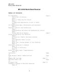
FRONT VIEW OF CHASSIS
A
front view of the completed
receiver. From left to right
the controls aloog the bottom are: standby switch, regeneration, oscillator, bandset, tuning, aerial bandset, audio volume, phone jack. The switch above the phone
jack selects •phone or loudspeaker output. To the left of the dial is the I.F. gain
control with the tone switch on the right. The dial can be chosen to meet individual taste, but it should have a smooth, positive action.
PLUG-IN COILS
Realising that low-capacitance tuning condensers will be used, several
sets of tuning coils are necessary to
cover the desired short-wave bands.
Home-wound plug-in coils are used
for simplicity and for flexibility. There
being no tuned RF stage, an aerial and
an oscillator coil are necessary for each
band.
The choice of converter valves is
limited, but the intermediate frequency
channel provides some food for
thought.
A long process of development ha:
resulted in the evolution of efficient
455 kc IF transformers, which are now
more or less standard equipment in
broadcast and dual-wave receivers
But a 455 kc IF channel has certain
disadvantages for a purely short-wave
receiver.
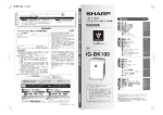
REAR VIEW OF RECEIVER
INTERMEDIATE FREQUENCY
One disadvantage is that only 910
kc (455 x 2) separates a sig'nal from
its "image" position. Again, the required beat frequency can be produced
in the IF channel by a wanted signal
and by another unwanted carrier
which happens to be 910 kc away from
it. And at high signal frequencies the
signal tuned circuits may not be selective enough to discriminate against
the unwanted carrier or image.
GAIN CONTROLS
Then there is the matter of oscillator "pulling," which begins to show
up at frequencies about 30 megacycles
To function normally, the local
oscillator must operate on a frequency
455 kc removed from the incoming
This rear view shows how the aerial terminals, coil wiring, tuning condenser and
converter valve assembly al'e all supported above he chassis, in the interests of
short leads. The bus-bar from the aerial tuning condenser_ can be seen running
straight down through the chassis to the aerial bandset condenser. The oscillator
condensers are similarly connected. There is useful space for a beat oscillator
immediately behind the power transformer.
(Continued on Next Page)
PAGE. NINETEEN .
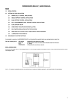
CIRCUIT OF THE "1946 AMATEUR JUNIOR" RECEIVER
6U7-G
6J8-G
7"
•
Mounted in oscillator bracket assembly
1946 AMATEUR JUN/OR
lommiumormamminamora.
The circuit reveals many well-tried features as well as some new ones. The set has every essential control and a particularly
neat connection for phones and tone control.
(Continued from Page 19)
carrier frequency. The percentage difference is actually not very great and,
depending on the exact circuit arrangement, there is a tendency for the local
oscillator to "lock in" with the incoming carrier and thus produce no
output at intermediate frequency.
All these difficulties are minimised
by increasing the intermediate frequency and, in fact, this practice is
commonly followed in short-wave
superheterodyne receivers,
and other
Gain control of the
pre-detector stages can be automatic
(AVC) or manual, according to the
degree of circuit complexity which
can be tolerated. Automatic volume
control is a handy feature when listening to fading phone stations but it is
undesirable for most morse transmissions. In many cases, under these conditions, the AVC action causes the background noise to intrude in a most disconcerting fashion between each break
in the signal.
In other words, AVC is not a feature
to include haphazardly in a short-wave
set. Its effectiveness and time constant
must be carefully considered, and
means provided to render it inoperative
when necessary.
BEAT OSCILLATOR
Yet another requirement for the reception of Morse transmissions is a
beat oscillator.
This can be covered by arranging
for portion of the set to oscillate —
generally the detector. Alternatively,
one may provide a separate beat frequency oscillator stage to heterodyne
the incoming signal as it passes
through the IF channel. The beat
oscillator is conventionally fitted to
larger amateur and communications
receivers, but It normally entails the
use of an extra valve. Our new set
uses a regenerative second detector of
simple and proved design.
Coming to the detector and audio
stages, the requirements in regard to
fidelity and high power are less rigid
than with conventional broadcast receivers. In fact, high fidelity may be
an undesirable feature.
As often as not, interest centres in
weak signals which are heard through
a solid background of noise.
The
essential thing is to obtain the greatest clarity of speech, or, alternatively,
the clearest Morse tone possible.
TONE CONTROL
By deliberately attenuating the bass
response or the treble response, or even
both together, a lot of the noise can
be cut out while still preserving the
middle register, where the vital speech
or tone frequencies are centred. So one
can expect a tone-control arrangement
in a communications superhet quite
distinct from the type found in broadcast receivers.
On top of that are other essential
details like provision for earphones,
with an earphone/loudspeaker switch.
Perhaps a "standby" switch to render
the receiver inoperative, while keeping
the valve heaters alight.
ALL NECESSARY
All these accessories add up to quite
an impfessive array of controls. They
are all desirable for convenience in
amateur working, and are not included
just to make the receiver panel look
impressive.
One could talk at great length about
the electrical features essential to an
amateur or communications receiver;
of the mechanical rigidity which is so
necessary to maintain frequency stability, and of the need to use the best
possible components and a smooth dial
movement.
However, further details along these
lines will emerge as we go on from
here to describe our new receiver.
Setting about the Ciesigil • of the receiver, it was a pleasant change to
plan it all on the drawing board and
know that a chassis could be made
to exact specifications. The layout is
(Continued on Page 23)
COIL-WINDING DATA
BAND
32-18 Mc/s
(9.4-16.7m.)
19-9.6 Mc/s
(15.8-31.3m.)
11.5-5.8 Mch
(26-52m.)
6.2-3.2 Mc/s
(48-94m.)
COIL
DIA.
Aer.
Osc.
fin.
fin.
Aer.
Osc.
14-in.
Aer.
Osc.
1 n.
Aer.
Osc.
I-kin.
I4-in.
LENGTH
PRI.
SEC.
2
6
61
6
lin.
lin.
2
4
9
81
I ain.
3
5
17
16
fin.
fin.
5
7
27
25
I4-in.
Coils for 3-6 Mc. band wound entirely with 22 B&S DCC. All other primaries
wound with 30 B&S DSC and secondaries with 18 B&S enamel. All windings in
the same direction. See text for further details.
PAGE TWENTY-ONE
such that it meets present requirements very nicely and leaves room
for future elaboration of the circuit.
A distinctive feature of the layout
is the position of the converter valve,
which lies horizontally
across the
chassis. This arrangement is technically sound and makes possible very
short leads in both the signal and oscillator circuits, as the tuning condensers, bandset condensers, and tuning
coils are grouped within an inch or so
of each other.
S
EaYth
•
•
13"
617-4
AERIAL CONNECTION
Two aerial terminals are/ mounted
on a small bakelite panel above the
rear edge of the chassis. These connect to the respective ends of the
aerial coil primary and permit the
use of twisted or transposed aerial
feeders.
When a single aerial lead-in is
used, the terminal connecting to
the lower end of the primary must
be bridged across to the earth
terminal, which is mounted on
the rear of the chassis.
The socket for the plug-in aerial
coil is mounted on pillars just near the
aerial terminals, so that the interconnecting leads are quite short. So also
is the lead from the "grid" pin of
the coil to the grid cap of the converter valve and to the stator plates
of the aerial tuning condenser.
In the original set, a small solder
lug was mounted under the rear stator
assembly bolt to make the lead even
more direct.
The oscillator tuning condenser is
mounted immediately behind the dial
in front of the aerial condenser, and
the space occupied by the shafts and
coupling brings the oscillator stator
plates right alongside the base pins
of the valve. Here again, the leads
are much shorter than would be possible had conventional layout been
used.
OIFT2
j
!FT
10"
0
6U7-4
„
wsc.1 e
Coil r I
I 11
, 0sc.,
bY6-6
5Y3-4
Tone
•
SpkT,
0
Phones
BANDSET CONDENSERS
The aerial and oscillator or bandset
condensers are mounted below the
chassis, but in such a way that they
are easily connected in parallel with
the ganged tuning units. A quarterinch hole is drilled through the chassis
and the respective sets of stator plates
connected by a short busbar which
passes straight up through each hole
with a minimum capacitance effect to
chassis.
All four tuning condensers need to
be mounted on angle brackets which,
in the case of the ganged units, must
be about two inches high to allow the
spindles to fit conveniently to a standard type of dial.
In ganging the main tuning condensers, great care is necessary to see
that the spindles are exactly in line
before the coupling is installed. Misalignment caused by bad mounting or
even unequal pressure in the coupling
grub-screws, will cause the condensers
to "weave" badly as the dial is rotated.
The same remarks apply for the
bandset condensers, which need to be
operated from the front panel through
extension shafts. Weaving and spring-
Standby
•
•
Re 90%.
Ou..
Tuning
•
INvilandsets
Ret.
•
Audio
'Phones
•
14”
11"1
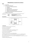
Drawn one quarter full size,
these sketches show the main
holes in the chassis and front
panel and also. in dotted outline, the position of the aerial
terminal strip, tuning condensers, coils and converter
valve assembly. A ready
punched steel chassis should
be available immediately
through normal supply houses, but the condenser
mounting and converter valve brackets will still need to
be made from scrap metal.
Nontinued on Next Paget
PAGE TWENTY-THREE
(Continued from Previous Page)
JOHN MARTIN
announces
AEGIS
KIT SETS
ing of these condensers will make
them particularly difficult to adjust,
as they are normally fitted with a
direct-drive knob.
The main oscillator tuning condenser is driven direct from the dial to
minimise the effects of backlash which
may develop in the coupling between
the tuning condensers. Jut in passing,
a fibre bush was used instead of the
usual brass bush between the dial
collar and the tuning condenser
spindle. The chance of noise originating in the dial mechanism is thus minimised by •avoiding possible noisy metalto-metal contact.
OSCILLATOR TUNING
The layout arrangement calls for a
bracket to carry the oscillator
valve and oscillator coil. This bracket
was made up from scrap aluminium,
with two small flanges to permit rigid
boltinz to the chassis.
Two valve socket holes are required
in this bracket, one to carry the converter valve horizontally, and the other
to carry the vertically-mounted oscillator coiL These holes are best cut
and the mounting holes drilled before
the bracket is bent. Make sure that
the valve holes are far enough apart
so that the socket lugs will not foul
when they are finally mounted in
place.
Use the best sockets you can get for
*
We have not had the time
or opportunity to test this receiver on the 50-54 ni.c. band. We
intend to do some work with it during the next few weeks, and expect
it to behave quite well in that region.
Look for results in -Radio and Fro b.
bies" for Mayl
Limited supplies are
beginning to arrive
the tuning coils and the converter
vale. e. A steatite or amphenol type
is a good selection, but beware of any
socket which has the appearance of
having been. "impregnated" with flux.
You will find that the leads between
the converter valve socket and coil
pins are less than an inch long in
most cases.
Make sure that the brackft fits the
chassis, then wire it all up before
mounting in place, Inside the bracket
you will have to tuck away the oscillator grid condenser, grid resistor,
Call or write for full
particulars to-
116-118 Clarence Street, Sydney.
Telephone BW3109 (3 lines). Telegrams: "Jonmar," Sydney.
• PAGE TWENTY-FOUR
cathode resistor and bypass, screen bypass and oscillator anode bypass.
Leads coming out include two for
the heater and one each for the oscillator B± supply, screen supply and
mixer plate. These pass down through
a hole in the chassis to their respective destinations.
Double check your wiring and re-;ord the chosen coil connections before
you mount this unit in place, for it
is not a pleasing job to have to dis'onnect it all to correct some suspected
fault.
One lead will need to come out the
side of the oscillator bracket to the
stator plates of the tuning condenser.
It is also a good idea to cross-connect
- he earth points of the condenser and
oscillator assembly, and run another
UNDER-CHASSIS VIEW OF SET
MULLENS
Technical
Books
RADIO
Bernard's—Manual of Shortwave Technique and Instructional Broadcast Re.
ception ..
Bernard's—Radio Coil and
Transformer Manual ..
Pocket
Bernard's—Radio
Book
•;••••
Ray
Bernard's—Cathode
Oscelloscope Manual
.
Bernard's—Manual of. Direct
Disc Recording .
• Radio
Bernard's—Bulgin
Service Manual
Bernard's—Radio Valve Man-
...............
. . ........
Note mounting and extension shafts for band-set condensers. Also cut-out and
mounting for tuning dial. Other points include shielded leads and neat layout.
earth-wire through to the bandset condenser.
But be particularly cateful to
avoid unnecessary stray capacitance
effects between the oscillator grid
circuit and chassis. Allow a bit of
air space around the condenser,
resistor, and grid circuit leads.
Corning to the converter valve itself,
We decided to use the well-tried 638-G.
Despite temporary shortages and talk
of other valves, the 6J8-G is likely to
remain the most readily available converter for many months to come, and
it was, therefore, the logical choice.
Experimental work with other com
ers may follow at a later date.
I.F.
EXPERIMENTS
gain, but fair overall, inadequate selectivity for our purpose.
We gained the impression that two
IF stages with reaction, using these
coils, would be practicable, but as we
desired only one IF stage, we changed
to 465kc. intermediate,%
1900K.C. INTERMEDIATES
Coil manufacturers at our request
have since intimated their intention
of resuming production of IF transformers for 1500 or 1900 kc/s., but at
the time of writing their technical features are unknown. As gain and selectivity are likely to be poorer than with
existing 455 kc/s units, a two-stage
IF channel may also be necessary using
them.
With all this in mind, standard ironcored IF transformers were ultimately
installed, and subsequent testing has
confirmed the wisdom of this choice
for our particular circuit requirements.
The IF amplifier valve is an ordinary 6U7-G, with a variable cathode
resistor to permit control of IF gain.
A voltage divider supplies the screen
loltage for this and the converter
valve. It is noteworthy that, although
both screens are supplied from the
same point, two separate bypass condensers are used, one on each of the
sockets.
The operating conditions are quite
conventional. The idea of oscillator
plate tuning was considered, but, at
this stage, there did not appear to be
sound reasons for adopting the unorthodox.
The plate lead of the converter
passes down through the chassis to
the first IF transformer. And here we
recall previous discussion.
Knowing the advantages of a higher
frequency IF channel—and the scarcity of suitable transformers—the set
was tried out with standard ironi
cored RF coils in place of the conventional IF transformers. Tuned with REGENERATION
small "postage stamp" trimmers, these
were found to resonate very nicely at
Regeneration is something of a proba little over 2000 kc/s.
lem with conventional IF transformers,
By including an RF coil with reaction which have no tertiary feedback windin the last position, a very neat set- ing. But the problem was solved by
(Continued on Next Page),
up promised. A practical test showed
Price Post
3/2 .. 21/2d
3/2 .. 21/2d
1/8 .. 11/2 d
3/2 .. 21/2 d
3/2 .. 21/2 d
4/- .. 21/2 d
5/6 .. 21/2 d
Terman—lkadio Engineers'
1/3
Har.Ubook
.
. 42/to
Tucker—Introduction,
6d
20/3 ..
Practical Radio
Radio Amateurs Handbook
4U
3/6 ..
Defence Edition .. .
Simon—Radio Service Trade
9d
21/Kinks
.. •• • • •
Kiver—U.H.F. Radio Sim6d
26/plified ..
Nit- on and Horning—Prac1/tical Radio Communication 42/Ghirardi—Radio Physics
Course ..
.. • • 40/- .. 1/6
Ghira.45i—Modern Radio Ser40/- .. 1/6
vicing ..
Cooke—Mathematics f o r
Electricians and Radio28/- .. 1/men ..
Cookin6•—Wireless Service
Manual .. _
12/6 .. 3U
Almstead and Tushill—Radio
4d
14/- ..
Material Guide •
De Forest—Television Today and Tomorrow .. • 27/- .. 4d
Everett—Communication En35/-.. 9d
gineering •
at
Meter
Rider—The
1S/••
Work
Admiralty Handbook of
Wireless Telegraphy, Vol3d
7/3 • •
. ..
ume I.
Admiralty Handbook of Airireless Telegraphy, Volume I.L. 11/- • •
Gd
ELECTRICAL
Vitlig-comb—Electri\cAy To'9
day
Smith — Tes'ting Dynamos
0.1
and E. Motors 15;6
MacFarlane — Electricity
3d
5/in the House
Muller—Garman and Drory
—Experimental Electron32/9
Dawes—Industrial Electri15/ 5
city Pt. I.
ElectriDawes—Industrial
6±1
.. 19/3 • .
city, Pt. H.
Coyne Electrician's
„ .. 23 6 ..
Handbook
Braymer and Roe—Rewind6d
ing Small Motors'. 17/6
Braymer and Roe—Rewindand
Connecting
Aling
ed
ternating Current Mctors 24/6
Amick—Fluorescent Light5d 1.
ing Manual ..
21/4 ..
Little Library of Useful Information. Price . • .. • •
1/9 • • 11/2d
Tool and Saw Sharpening—Cleansing
Preparations—Small Tables—Book Cases—
Turned Novelties-23 Shelves You can
Make—Lamps—Chemieal Experiments —
From Pattern to Casting—Build Your Own
Auto Trailer—Technique of Using Drills
and Wood Bits—Running a Metal Turning
Lathe—Wood Turning—Weaving and Recaning—"Skipper" 14-foot Outboard Runabout—House Wiring—Action Tovs—Electrorlating, Plain and Novelty. Wood Finishing—Small Sailboats—Spray Paintinfr—
Extra Rooms in Your Attic—Automobile
Kinks—How to Build Your Own 14-foot
Sailing Dinghy.
Concrete Garden Furniture—Serving Trays—Lawn and Garden Novelties—Mirror Silvering.
ROBERTSON and
MULLENS LTD.
107-199-111-113 Elizabeth St.,
MELBOURNE, CI.
PAGE TWENTY-FIVE:
FROM
FERGUSON'S
RADIO
Dear Mr. Radioman,
A „.
MULTIPURPOSE
TEST
INSTRUMENT
Is that what you've longed
for ?
Of course it is
Well that's the type of instrument you
have at your finger tips when you use
a Cathode Ray Oscillograph.
The number of different tests that an
amplifier can withstand and still come
through with flying colours determines
its final performance.
Practically every major race that a
HI-FI Amplifier has to run, is made
with a Cathode Ray Oscillograph in
the judge's box.
Ferguson's Radio, of Willoughby, are
now manufacturing a 3-inch cathcideray oscillograph equally suitable for
design laboratory or "ham shack."
Just look at these
performance
figures !
DEFLECTION AMPLIFIERS
FREQ. RESPONSE: Flat within 2db.
10-20,000 c/s.
INPUT: Continuously variable impedance 1.0 meg.
SENSITIVITY: 0.5 volts R.M.S. for
one inch deflection (low distortion).
DIRECT PLATE INPUT
INPUT: 2 meg. impedance
SENSITIVITY: 50 volts per inch
approx.
LINEAR TIME BASE
RANGE: 25 to 30,000 c/s.
THANKING YOU
FERGUSON'S RADIO
12 McMAHON STREET,
WILLOUGHBY. NSW. JA6 I 77
PI GE TWENTY-SIX
volume control, tone control and output grid, the leads are much longer.
However, only audio voltages are involved and shielding takes care of this
without ill effects.
With an IF gain and a reaction control, the audio gain potentiometer may
not appear essential. Perhaps it isn't,
but it is very handy in limiting the
audio power in the "brrrps" and squeals
for which the short-wave bands are
famous.
Very useful, too, is the tone control
switch which is rather unusual in its
action. In the centre position it gives
normal frequency response; on one side
the bass is cut severely, and on the
FEEDBACK COIL
other both bass and treble are attenuated, leaving only the middle freThe feedback coil in the "Communi- quencies.
cations Five" had about 100 turns of
Proper use of this control can make
about 30-gauge wire, jumble wound on a world of difference to the clarity
a lin. diameter former. A somewhat of signals, either phone or MorSe.
neater coil, as used in this set, consists of 125 turns of 30-gauge wire, OUTPUT STAGE
the same neat trick which was utilised
on our "Communications Five" and
other receivers of a few years ago.
It involves connecting a small inductance in series with the detector
cathode-to-earth return and shunting
it with a wire-wound potentiometer.
The latter may have a value of between 2500 and 5000 ohms, and the
inductance may be wound easily by
hand.
The general idea is to wind on just
enough turns to ensure reliable oscillation with the control well advanced.
Too mapy turns will make the regeneration "ploppy" in action.
jumble wound on a iin. bakelite bush
between two small bakelite cheeks.
The output stage is quite straightThese figures will be a good guide, but forward except for a special network
experiment for yourself and get the in the plate circuit to allow the use
best results.
of phones. when desired.
In the original set the reaction was
The output plate load is provided
very smooth with the IF' gain at maxi- by the normal loudspeaker transformer
mum, as would be the case when in series with a 400 ohm resistor at
searching for weak signals. With the the B-plus end. A two-way toggle
IF gain backed off, a slight ploppiness switch cuts out one or the other, as
is evident, but this is unimportant in required.
practice. Note that the lead from
When the loudspeaker is required,
cathode to the rethe switch simply
generation control
shorts-out the reshould be shielded.
sistor and the set
E got so darned interested in
Use of a leaky
operates in the
this
grand
little
set
that
the
t
grid detector and
normal f ash ion.
allotted
space
ran
out
too
soon!
regeneration comWith the switch
However,
all
the
constructional
deplicates the addiin the alternative
tails
are
here
allowing
you
to
go
tion of automatic
position, the loudahead with the job. Next month
volume control, alspeaker transforwe'll give you more about operation,
though it is still
mer is shorted-out
band coverage, and other matters
quite feasible. Howand an audio voltof a more general nature.
ever, it was felt
age developed
that an AVC sysacross the resistor,
tem and switching
(Owing to its comcould be added, if desired, at a later paratively low d-c resistance, the d-c
plate voltage of the output valve is
date.
............................Mill../....11..11.............M0,111....1
W
not greatly affected.)
The audio voltage is fed to one side
If you are keen to add AVC at some of the phone jack through a coupling
A.U.C. CIRCUIT
condenser, the other terminal being
earthed.
A resistor across the jack keeps the
condenser at earth potential at all times
so that there is no heavy "plop" as
the phones are plugged in while the
set is operating. Use a good condenser
and you can rest assured that the
phones will always be at earth potential as far as d-c is concerned.
The amplitude of signal in the phones
can be varied by altering the value
of the resistor, but 400 ohms gives a
nice balance between the output from
Output from the IF ampliher feeds loudspeaker and phones. It is posinto a leaky grid detector. This type sible to switch from one to the other
was chosen both for its selectivity and without having to alter the gain confor its adaptability to regeneration. trol setting.
As already explained, regeneration is
The switching operation could actunecessary to produce a beat note with ally be carried out by the jack itself,
unmodulated morse carriers. The only if it happens to be one with an insualternative would be a separate beat lated set of leaves giving a SPDT switch
oscillator stage, which requires another action.
valve and quite a few extra "bits." And,
Apart from a "stand-by" switch in
in any case, regeneration offers a useful the transformer high tension circuit,
increase in gain below the point of os- the power supply is quite conventional.
The single section filter reduces the
cillation.
time, we suggest that you purchase
a 6B8-G and use it in place of the
6J7-G detector. It will be just as
effective in ;this service and the diodes
are available for future use. Alternatively, an EBF2-G could be installed
as IF amplifier, leaving the diodes unused for the time being. There is a
nice spot in the front panel for the
AVC switch.
The layout of the chassis up to this
point follows logical sequence and allows for short leads and freedom from
feedback paths.
From the detector plate across to the
hum level to the usual, low limit. How-
VIEW ABOVE THE SET CHASSIS
REPAIRS
...:... T
.
CALSTAN
EXPERTS
"
All the main components above the chassis are visible here. The well-grouped
Note terminals for
leads between valve, coils, and condensers is quite evident.
doublet-aerial connection and the angle bracket supporting the dial.
ever, if you are fussy on this score, and requirements will be clear from
it is a simple matter to add an extra what has already been said, and from
the diagrams and pictures. Once the
filter choke and condenser.
(Continued on Page 61).
Most of the constructional methods
The new Repair Department at
Zenith is the answer to a long felt
want. Having secured the services
of a highly qualified instrument
maker and technician with 35
years' experience, Zenith can now
effect repairs and adjustments to
all graphic recording and standard
and substandard electrical instruments. For dependable repairs
consult Zenith.
CLOSE-UP OF TUNING SECTION
(GALi6ra/ed to STANdard)
MULTIMETER AND
OUTPUT METER
MODEL 511 AC-DC
wide voltage, current and resistance ranges. Portable, attractive
and completely reliable.
CALSTAN
D.C. MULTIMETER
Guaranteed within 2 per cent.
accuracy. In sturdy black case
and complete with test leads..
CALSTAN
MODELS 223A
AND 223AV
Analyser and valve checker.
QUALITY PRODUCTS
OF
Zenith
vgimi
COMPANY prr: frar:
This close-up illustrates in detail many of the points in the top picture. It also
gives an excellent idea of the 10-metre coils mounted within valve bases.
131-133 Palmer Street
(off William Si:), Sydney, FA2I57
I-5
PAGE TWENTY-SEVEN
THE 1946 AMATEUR JUNIOR I
(Continued from Page 27)
pass_ through. Drill another hole for
the grid end of the winding the specified distance from the first, so that
the overall length of the coil will
automatically be right.
Connect one end of the wire through
to the base pin in the coil former,
unroll the amount of wire you anticipate will be necessary to wind the coil,
and then clamp the reel in the vice.
Keeping the wire taut, begin your
winding moving towards to the reel
as the wire is taken up. Space the
winding slightly as you go, put on the
required number of turns, cut the wire,
and finally push the end through hole
and solder to the base pin.
aerial and oscillator coils to avoid
If the wire has been put on tightly
and without kinking, it should now be
possible confusion between them.
Thus, a set of 5 and 6-pin formers possible to move it along with the finis a good choice. We used 6 and 7-pin gers until a nice even spacing is-
wiring has been completed and
checked, there remains the last big job
of winding up the various sets of
coils.
The performance of the receiver will
largely be governed by the coils, so
that any amount of trouble is justified
in making the best possible job of
them. Cleanliness, rigidity and accuracy are the points to watch.
Four distinct connections have to
be made to each aerial and oscillator
coil, so that four-pinned formers
would suffice. ,However, an extra pin
or two is handy for possible elaboration
at later date. Also, it is a good idea to
have a different number of pins on the
formers because they happened to be
on hand.
It is not particularly important just
how you bring the coil endings to the
respective pins. Tile main point is tc see,
when the former is ultimately plugged
into the socket, that the two windings are conneced correctly into circuit with the shortest possible leads.
CONNECTION TO PINS
All windings must go on in the same
direction. Referring to the aerial coils,
the connections must be such that the
top of the secondary (further away
from the pins) goes to grid and the
bottom to earth. The top of the small
primary winding must connect to the
main aerial terminal and the bottorri to
the second aerial terminal, which is
normally grounded.
Top of all oscillator secondaries (the
heavy winding) goes to the oscillator
grid condenser and the bottom to earth.
Top of all oscillator primaries goes to
B-plus and the bottom to oscillator
plate.
The coil for the 3 to 6 megacycle
band is the simplest to wind and is
best tackled first. Drill a small hole
through the former about iin. from
the bottom for the bottom of the grid
winding, and another a little less than
an inch above it for the top of the
winding. Then close wind the stated
number of turns, using 22g DCC
covered or some similar gauge.
SPACING
The primary can then be fitted in
the space below the grid winding *and
comprising the stated number of turns
for the aerial and oscillator coils. Space
the windings about 1/16th inch in
the case of the oscillator coil and
about 1/8th inch in the aerial coil.
Connect the windings through to the
base pins, plug the coils into the
sockets, and check to see that the windings connect into circuit as required.
The secondaries of the remaining six
coils are all wound with 18 gauge
enamel or similar wire, the windings
being spaced out according to the
tabulated data.
Start all secondaries about a quarter
inch from the bottom of the former,
drilling a small hole for the wire to
achieved along the full length of the
coil.
PRIMARY POSITION
Note the position the primary will
now occupy and drill holes for the top
and bottom; to drill the top hole you
will need to part the heavy wires
slightly. Using the fine wire specified,
or similar, wind on the specified primary turns, keeping the wire central
between the turns of the secondary.
For the aerial coils on each of
the higher-frequency bands, the
primary winding is started near
the bottom of the. secondary and
interwound turn for turn. But
there is an important difference in
the oscillator coils, in that the
primaries are only part interwound.
Thus, in the 6-11 megacycle coil, the
bottom turn is wound close under the
bottom of the secondary, with the
other four turns interwound. And, in
the 9-19 megacycle coil, two of the
four turns are around the bottom of
the secondary and the other two interwound.
COILS FOR 18-32 M.C;
For the 18-32 megacycle coils, no
attempt was made to use the standard
llin. formers because of the poorlyshaped coil which would result. The
coils were wound instead on short
lengths of tin. diameter paper bakelite and then mounted inside two suitable valve bases. In the oscillator coil
three of the primary turns are around
the bottom of the ,secondary and three
interwound.
If your coils are wound exactly to
specifications, and stray capacitances
in the receiver kept to a minimum,
band coverage figures should be very
close to those obtained in the original
set. If a check shows all to be in-
order in this respect, it is a good idea
to coat the coils with trolitul or other
good insulating varnish, or with maclac or pure paraffin wax. This will
hold all turns firm and help to maintain accurate calibration.
But enough for the present. Next
month we hope to have more to say
about the operation of the "1946
Amateur Junior."
PAGE :SIXTY-CoNi