1
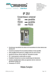
IF51
Manuale d'uso
IF51
Descrizione
IF51 è un convertitore compatto ed economico e tuttavia estremamente
performante adatto per tutte le applicazioni industriali in cui l'informazione
trasmessa da un sensore o un encoder con interfaccia SSI debba essere
convertita in un segnale analogico oppure in una stringa dati in formato seriale
RS-232/RS-485.
L'unità è stata progettata per ospitare in un alloggiamento di dimensioni
contenute una morsettiera a 12 poli e un connettore SUB-D 9 poli femmina. La
custodia si presta all'installazione con sistema di fissaggio secondo le norme
DIN.
Elenco sezioni
1 - Norme di sicurezza
2 - Identificazione
3 - Introduzione
4 - Istruzioni di montaggio
5 - Connessioni elettriche
6 - Impostazione degli switch DIL
7 - Messa in servizio
8 - Lettura della posizione encoder mediante interfaccia seriale
9 - Configurazione da PC mediante il software operatore OS3.2
10 - Parametri di impostazione
11 - Programmazione libera della linearizzazione
12 - Funzioni di test
13 - Lista parametri
MAN IF51 I_E 1.0.odt
1 / 56
IF51
1 - Norme di sicurezza
1.1 Sicurezza
• Durante l’installazione e l’utilizzo del dispositivo osservare le norme di
prevenzione e sicurezza sul lavoro previste nel proprio paese;
• l’installazione e le operazioni di manutenzione devono essere eseguite da
personale qualificato, in assenza di tensione e parti meccaniche in
movimento;
• utilizzare il dispositivo esclusivamente per la funzione per cui è stato
costruito: ogni altro utilizzo potrebbe risultare pericoloso per l'utilizzatore;
• alte correnti, tensioni e parti meccaniche in movimento possono causare
lesioni serie o fatali;
• non utilizzare in ambienti esplosivi o infiammabili;
• il mancato rispetto delle norme di sicurezza o delle avvertenze specificate
in questo manuale è considerato una violazione delle norme di sicurezza
standard previste dal costruttore o richieste dall'uso per cui lo strumento è
destinato;
• Lika Electronic s.r.l. non si assume alcuna responsabilità per eventuali danni
o lesioni derivanti dall'inosservanza delle norme di sicurezza da parte
dell'utilizzatore.
1.2 Avvertenze elettriche
• Effettuare le connessioni elettriche esclusivamente in assenza di tensione;
• rispettare le istruzioni relative alle connessioni riportate nella sezione “5 Connessioni elettriche”;
• in conformità alla normativa 2004/108/CE sulla compatibilità
elettromagnetica rispettare le seguenti precauzioni:
- prima di maneggiare e installare il dispositivo, eliminare la presenza di
carica elettrostatica dal proprio corpo e dagli utensili che verranno in
contatto con il dispositivo;
- alimentare il dispositivo con tensione stabilizzata e priva di disturbi, se
necessario, installare appositi filtri EMC all’ingresso dell’alimentazione;
- utilizzare sempre cavi schermati e possibilmente “twistati”;
- non usare cavi più lunghi del necessario;
- evitare di far passare il cavo dei segnali del dispositivo vicino a cavi di
potenza;
- installare il dispositivo il più lontano possibile da eventuali fonti di
interferenza o schermarlo in maniera efficace;
- minimizzare i disturbi collegando l'unità a un buon punto di terra (GND).
Assicurarsi che il punto di terra sia privo di disturbi. Il collegamento a terra
può essere effettuato sul lato dispositivo e/o sul lato utilizzatore; è
compito dell’utilizzatore valutare la soluzione migliore da adottare per
minimizzare i disturbi.
MAN IF51 I_E 1.0.odt
1 - Norme di sicurezza
2 / 56
IF51
1.3 Avvertenze meccaniche
• Montare il dispositivo rispettando rigorosamente le istruzioni riportate
nella sezione “4 - Istruzioni di montaggio”;
• non disassemblare il dispositivo;
• non eseguire lavorazioni meccaniche sul dispositivo;
• dispositivo elettronico delicato: maneggiare con cura; evitare urti o forti
sollecitazioni sia all’albero che al corpo del dispositivo;
• utilizzare il dispositivo in accordo con le caratteristiche ambientali previste
dal costruttore.
2 - Identificazione
Il dispositivo è identificato mediante un codice di ordinazione e un numero di
serie stampati sull'etichetta applicata al dispositivo stesso; i dati sono ripetuti
anche nei documenti di trasporto che lo accompagnano. Citare sempre il codice
di ordinazione e il numero di serie quando si contatta Lika Electronic s.rl. per
l'acquisto di un ricambio o nella necessità di assistenza tecnica. Per ogni
informazione sulle caratteristiche tecniche del dispositivo fare riferimento al
catalogo del prodotto.
3 - Introduzione
IF51 è un convertitore compatto ed economico e tuttavia estremamente
performante adatto per tutte le applicazioni industriali in cui l'informazione
trasmessa da un sensore o un encoder con interfaccia SSI debba essere
convertita in un segnale analogico oppure in una stringa dati in formato seriale
RS-232/RS-485.
L'unità è stata progettata per ospitare in un alloggiamento di dimensioni
contenute una morsettiera a 12 poli e un connettore SUB-D 9 poli femmina. La
custodia si presta all'installazione con sistema di fissaggio secondo le norme
DIN.
Encoder e sensori compatibili
E' possibile collegare all'unità IF51 encoder monogiro e multigiro e
trasduttori similari provvisti di interfaccia SSI standard (da 6 a 25 bit di
risoluzione con codice Binario o Gray). L'unità può funzionare sia in
modalità Master (con segnale di clock generato dall'unità IF51) che in
modalità Slave (dove il segnale di clock è generato dal dispositivo remoto).
Nota sulla risoluzione dell'encoder
L'unità permette l'impostazione per risoluzioni standard di 13, 21 e 25 bit. In
generale, per sensori che dispongano di risoluzioni diverse è possibile
impostare la risoluzione immediatamente superiore (per esempio, impostare
l'unità a 21 bit quando si collega un trasduttore a 16 bit). A seconda del
costruttore e delle caratteristiche dello specifico apparecchio, talora può
rendersi necessaria la soppressione dei bit in eccesso utilizzando la funzione
di bit blanking descritta in seguito, si veda il paragrafo “Considerazioni
sull'uso della funzione di soppressione dei bit (bit blanking function)” a
pagina 18. Tuttavia generalmente il dispositivo lavora correttamente anche
senza alcuna particolare soppressione dei bit.
MAN IF51 I_E 1.0.odt
3 - Introduzione
3 / 56
IF51
4 - Istruzioni di montaggio
ATTENZIONE
Effettuare il montaggio meccanico esclusivamente in assenza di tensione.
Il convertitore IF51 deve essere installato e protetto all'interno di un quadro
elettrico. Dispone di sistema di fissaggio secondo le norme DIN e può perciò
essere agevolmente montato su guide DIN mediante le clip predisposte nella
parte posteriore che non richiedono ulteriori supporti.
MAN IF51 I_E 1.0.odt
4 - Istruzioni di montaggio
4 / 56
IF51
5 - Connessioni elettriche
ATTENZIONE
Effettuare le connessioni elettriche esclusivamente in assenza di tensione.
L'immagine riportata appena qui sotto mostra l'assegnazione dei poli della
morsettiera.
Raccomandiamo di collegare il polo negativo (Meno) dell'alimentazione
dell'unità alla messa a terra.
I terminali GND 4, 6 e 12 sono collegati internamente. A seconda della tensione
d'ingresso e del carico dell'uscita di tensione ausiliaria, il consumo totale
dell'unità arriva a circa 200 mA.
5.1 Collegamento dell'encoder in modalità Master
Raccomandiamo di collegare la calza del cavo dell'encoder al polo negativo
dell'alimentazione dell'encoder su entrambi i lati.
MAN IF51 I_E 1.0.odt
5 - Connessioni elettriche
5 / 56
IF51
5.2 Collegamento dell'encoder in modalità Slave
In questa modalità il convertitore IF51 funziona in parallelo a un'altra
apparecchiatura, ponendosi, per così dire, “in ascolto” della comunicazione dati
esistente.
In base alle necessità, il potenziale di riferimento del Master può essere collegato
al morsetto 12 (GND) oppure rimanere non collegato, utilizzando così un modo
di funzionamento differenziale senza potenziale di riferimento.
5.3 Uscite analogiche
L'unità dispone di un'uscita di tensione +/-10V e una uscita di corrente 0-20 mA
/ 4-20 mA a una risoluzione di 14 bit (vale dire che l'uscita di tensione opera con
passi di 1.25 mV).
L'uscita di tensione presenta un carico nominale di 2 mA; l'uscita di corrente
presenta un carico compreso tra 0 e 270 Ohm.
E' presente un terminale di massa analogica separata internamente collegato al
terminale di massa GND dell'alimentazione del dispositivo.
Vout
GND
1
4
Voltage output
MAN IF51 I_E 1.0.odt
+/ - 10V
Iout
(max. 2 mA)
GND
7
4
0/4 - 20 mA
(R = 0 ... 270 Ohms)
Current output
5 - Connessioni elettriche
6 / 56
IF51
5.4 Interfaccia seriale
Il dispositivo è equipaggiato con due interfacce seriali, una RS-232 e una RS485; tuttavia è possibile utilizzarne una sola per volta. La comunicazione seriale
permette la lettura della posizione dell'encoder e l'impostazione dei parametri e
delle variabili da PC, secondo la necessità.
MAN IF51 I_E 1.0.odt
5 - Connessioni elettriche
7 / 56
IF51
MAN IF51 I_E 1.0.odt
5 - Connessioni elettriche
8 / 56
IF51
6 - Impostazione degli switch DIL
Gli switch DIL sono alloggiati nella parte superiore dell'unità e permettono di
configurare i parametri dell'apparecchiatura specifici per il funzionamento
voluto.
La configurazione degli switch mostrata nella Figura sopra si riferisce a un
encoder SSI con risoluzione di 25 bit e uscita in codice Gray, in modalità
operativa Master. L'uscita analogica opera con cicli di aggiornamento fissi e la
comunicazione seriale è configurata nel formato RS-232.
NOTA
Le modifiche nell'impostazione degli switch diventano effettive solo alla
successiva riaccensione del dispositivo!
ATTENZIONE
Al termine dell'operazione di configurazione, avere cura di ripristinare lo switch
DIL 6 TEST SSI nella posizione ON. Se impostato a OFF, anche un tocco
involontario del pulsante TEACH porterebbe alla cancellazione delle precedenti
impostazioni!
MAN IF51 I_E 1.0.odt
6 - Impostazione degli switch DIL
9 / 56
IF51
7 - Messa in servizio
In semplici applicazioni con funzioni di base, si può utilizzare la procedura di
TEACH per la messa in servizio dell'unità. Funzioni più evolute richiedono
l'utilizzo del software operatore su PC e sono descritte più avanti.
7.1 Auto-test
Impostare gli switch DIL in funzione delle caratteristiche della propria
applicazione e collegare l'encoder e l'alimentazione al dispositivo. Impostare
anzitutto lo switch 6 TEST SSI a ON (modalità Test SSI) e fornire poi tensione
all'apparecchiatura. Entrambi i led verde (alimentazione) e giallo (stato) si
devono accendere. Al termine di un auto-test con esito positivo, dopo circa 1
secondo il led giallo si deve spegnere.
7.2 Test segnale SSI
Premere ora il pulsante TEACH una volta. Questo avvierà il controllo delle linee
di trasmissione dati SSI. Il led giallo deve accendersi. Se rimane spento, sarà
necessario invertire i due ingressi “DATA+” (9) e “DATA-“ (8).
Premendo il pulsante TEACH una seconda volta l'unità avvierà il test sulla linea
clock SSI con le medesime modalità del test precedente. Di nuovo il led giallo
deve accendersi, altrimenti è necessario invertire i due ingressi “CLOCK+” (3) e
“CLOCK-“ (2)1.
Alla pressione del pulsante TEACH per la terza volta il led giallo si spegnerà
indicando così che il ciclo di test si è concluso.
Se il led di stato giallo si accende dopo la prima e la seconda pressione del
pulsante TEACH, questo significa che il collegamento dell'encoder è corretto.
Togliere quindi tensione all'apparecchiatura e impostare lo switch DIL 6 TEST SSI
a OFF per abilitare la procedura di TEACH. Utilizzando un PC e il software
operatore OS3.2, è possibile verificare gli stati delle linee dati e clock anche
attraverso i campi STATUS SSI-CLK e STATUS SSI-DATA nel box OUTPUTS (rosso
= stato ok).
7.3 Scaling dell'uscita analogica per mezzo della funzione TEACH
Fornire di nuovo tensione all'apparecchiatura con lo switch DIL 6 TEST SSI
impostato a OFF. Premere una volta il pulsante TEACH.
Il led di stato giallo inizierà ora a lampeggiare a bassa frequenza mentre l'unità
rimane in attesa che sia programmata la posizione zero (posizione iniziale).
Muovere perciò l'encoder e raggiungere la posizione che si vuole impostare
come iniziale; quindi premere di nuovo il pulsante TEACH.
In questo modo la posizione zero definita viene memorizzata e il led giallo inizia
a lampeggiare a una frequenza maggiore, in attesa che l'operatore imposti
1
Il test delle linee clock si rivela principalmente utile nella modalità operativa Slave.
Posto che il test funziona anche in modalità Master, in questo caso il risultato altro non mostra
che il corretto funzionamento nella generazione interna di clock. Tuttavia, in modalità Master, il
test non è in grado di indicare i segnali di clock difettosi né l'errato cablaggio degli ingressi
clock.
MAN IF51 I_E 1.0.odt
7 - Messa in servizio
10 / 56
IF51
anche la posizione full scale (posizione finale). Muovere perciò l'encoder e
raggiungere la posizione che si vuole impostare come finale; quindi premere
ancora una volta il pulsante TEACH.
Viene così memorizzata anche la posizione finale e il led si spegne. L'uscita
analogica è ora programmata nel range operativo desiderato, secondo la
definizione del parametro Output Mode.
NOTA
• La posizione full scale (posizione finale) può essere superiore o inferiore
alla posizione zero (posizione iniziale).
• Ulteriori funzioni di scaling e di linearizzazione sono disponibili
mediante la configurazione da PC.
• Teach Minimum si riferisce sempre al valore dell'uscita iniziale definito
mediante il parametro Output Mode, vale a dire 0V o 0 mA o 4 mA.
• Se, dopo l'impostazione della posizione full scale (posizione finale), il led
di stato giallo non dovesse spegnersi, questo significa che si è verificato
un errore di overflow; la posizione dello zero meccanico del vostro
encoder si trova cioè tra le due posizioni iniziale e finale programmate
(si veda la Figura sotto). In questo caso è necessario modificare la
posizione di zero dell'encoder (meccanicamente oppure mediante una
opportuna programmazione dell'encoder). Utilizzando l'interfaccia PC, il
convertitore medesimo è in grado di provvedere alla soppressione
elettronica del salto di overflow.
• La sola maniera per resettare uno stato imputabile all'errore di overflow
è quella di riaccendere l'apparecchiatura.
• Nel caso di encoder con risoluzione inferiore a 13 bit, l'errore di overflow
potrebbe non essere segnalato mediante il led.
Overflow error
Teach min.
Encoder zero
Teach max.
7.4 Ingresso SET
Se si invia un segnale con livello logico ALTO all'ingresso SET (switch DIL 10)
l'unità sostituisce temporaneamente il dato encoder SSI con il valore impostato
al parametro SSI Set value; l'uscita analogica e la lettura seriale si comportano
di conseguenza. Questo significa che indipendentemente dalla posizione
meccanica attuale dell'encoder l'unità utilizza il dato impostato nel registro SSI
Set value invece che il dato fornito dall'encoder SSI. Si ripristina la normale
lettura del dato encoder non appena il valore logico del segnale SET ritorna
BASSO. Questa funzione può rivelarsi estremamente utile per ogni necessità di
test e di messa in funzione. L'ingresso SET utilizza stadi PNP / HTL (BASSO =
aperto o 0–3V, ALTO = 10–30V).
MAN IF51 I_E 1.0.odt
7 - Messa in servizio
11 / 56
IF51
8 - Lettura della posizione encoder mediante interfaccia seriale
E' possibile leggere in qualsiasi momento la posizione SSI dell'encoder
utilizzando l'interfaccia seriale. E' necessario un PC per la configurazione dei
parametri di comunicazione.
L'unità IF51 utilizza il protocollo di comunicazione standard DRIVECOM
conforme alla norma ISO 1745.
Maggiori dettagli sul protocollo sono disponibili nel documento Serial Protocol
1a.pdf che può essere scaricato dal sito web di Lika Electronic.
Il codice di accesso seriale per la lettura della posizione encoder è „ :8 “ .
(caratteri ASCII per i due punti e 8)
MAN IF51 I_E 1.0.odt8 - Lettura della posizione encoder mediante interfaccia
seriale
12 / 56
IF51
9 - Configurazione da PC mediante il software operatore OS3.2
Mediante un PC e il software operatore OS3.2 è disponibile l'intera gamma di
funzionalità per la programmazione più completa del dispositivo. Il software e le
relative istruzioni d'uso si possono scaricare gratuitamente accedendo al sito di
Lika Electronic all'indirizzo www.lika.it.
•
•
•
Collegare il PC al convertitore utilizzando un cavo seriale RS-232
cablato secondo lo schema disponibile nella sezione “5.4 Interfaccia
seriale“ a pagina 7. Assicurarsi che siano collegati solo i pin 2, 3 e 5.
Avviare il software OS3.x, apparirà la seguente schermata:
Nel caso in cui i campi di testo e le segnalazioni colorate rimanessero
vuoti e nell'intestazione comparisse il messaggio OFFLINE, sarà
necessario controllare le impostazioni della porta seriale. Per fare
questo, premere il comando COMMS nella barra di menu. Le
impostazioni di default dell'unità impostate dai tecnici di Lika Electronic
sono le seguenti:
Numero unità 11, Bit per secondo 9600, start 1 / Bit di dati 7 / Parità
pari / Bit di stop 1
•
Se si ignorassero le impostazioni della seriale dell'unità, è possibile
avviare la funzione SCAN nel menu TOOLS per rilevarle.
MAN IF51 I_E 1.0.odt9 - Configurazione da PC mediante il software operatore
OS3.2
13 / 56
IF51
10 - Parametri di impostazione
10.1 Impostazioni di visualizzazione
X Operand
/ Operand
+/-Operand
Questi operandi sono utilizzati per convertire l'informazione della posizione
trasmessa dall'encoder in una differente unità di misura come per esempio i
millimetri o i pollici. La conversione riguarda esclusivamente il valore della
lettura numerica seriale e non attiene in alcuna misura all'uscita analogica.
X Operand
=
1.0000
/ Operand
=
1.0000 e
+/-Operand
=
0.0000
il valore letto serialmente corrisponde al valore effettivo dell'encoder.
Con le seguenti impostazioni
Serial Readout =
[ SSI encoder data
x
xOperand
/ Operand
]
+ +/ -Operand
10.2 Impostazioni generali
Teach Minimum
Teach Maximum
Questi due parametri definiscono i limiti minimo e massimo dell'encoder cui
l'uscita analogica deve far corrispondere i due valori di uscita minimo e
massimo. E' possibile utilizzare in qualunque momento il pulsante TEACH
nell'unità oppure i tasti TEACH MIN. / TEACH MAX. disponibili nel box INPUTS del
software operatore per impostare questi registri 2, a ogni modo è anche possibile
impostare direttamente i valori tramite la tastiera senza utilizzare la funzione
TEACH.
Round Loop
Come regola generale, questo registro dovrebbe essere impostato a 00000. Ogni
altra impostazione sostituisce la posizione reale dell'encoder con un ciclo
ripetitivo di conteggio.
ESEMPIO
Se si imposta questo registro a 2048, la rappresentazione interna della posizione
si muove all'interno del range 0 - 2047. Quando si supera il limite inferiore di
zero con un conteggio decrescente, di nuovo appare il valore 2047. Al contrario,
2
Premere una prima volta il tasto TEACH MIN. (on), quindi premerlo una seconda volta
(off); premere poi una prima volta il tasto TEACH MAX. (on), quindi premerlo una seconda volta
(off). Per attivare i dati acquisiti mediante la procedura Teach premere il tasto ACTIVATE DATA;
per leggere e visualizzare I dati acquisiti mediante la procedura Teach premere il tasto READ.
Tutti i valori saranno poi memorizzati nell'unità mediante la pressione del tasto STORE EEPROM.
MAN IF51 I_E 1.0.odt
10 - Parametri di impostazione
14 / 56
IF51
quando si oltrepassa il limite superiore 2047 con un conteggio crescente, si
raggiunge il valore 0 e così via.
La posizione zero del contatore round loop può essere impostata nel registro SSI
Offset che permette dei valori compresi tra 0 e l'impostazione Round Loop. Il
registro Direction permette invece di impostare la direzione di conteggio del
contatore round loop (0 = crescente, 1 = decrescente).
All'interno di questa nuova definizione del range round loop, si ha la libertà di
impostare nuovamente la soglia iniziale zero e il valore full scale (cioè finale)
dell'uscita analogica mediante i parametri Teach Minimum e Teach Maximum.
Le immagini che seguono esemplificano chiaramente il rapporto tra i dati
originali dell'encoder, l'impostazione Round Loop e i registri SSI Offset e
Direction.
8192
Original encoder signal
Encoder 13Bit
Direction = 0
SSI-Offset = 1024
Round-Loop = 2048
Round-Loop signal
2048
T-Max
1024
T-Min
180
0
SSI-Offset = 1024
360 degrees
Round-Loop= 2048
Volt
Analogue Output (Output Mode = 1)
8192
Original encoder signal
Encoder 13Bit
Direction = 1
SSI-Offset = 1024
Round-Loop = 2048
Round-Loop signal
2048
1024
T-Max
T-Min
180
0
SSI-Offset = 1024
360 degrees
Round-Loop= 2048
Volt
Analogue Output (Output Mode = 1)
MAN IF51 I_E 1.0.odt
10 - Parametri di impostazione
15 / 56
IF51
La funzione ROUND LOOP si rivela particolarmente utile anche per eliminare
l'overflow dell'encoder, quando la posizione dello zero meccanico si venga a
trovare tra i due limiti impostati in Teach Minimum e Teach Maximum e non
si intenda apportare modifiche alla configurazione meccanica. Come mostrato
nella Figura in basso, è necessario impostare il registro Round Loop alla
risoluzione completa dell'encoder e quindi spostare la transizione zero
impostando il parametro SSI Offset di conseguenza.
NOTA
• Ogni volta in cui si cambia il valore del registro Round Loop, bisogna
poi necessariamente impostare nuovi valori anche nei registri Teach
Minimum, Teach Maximum e SSI Offset.
• Utilizzando la funzione ROUND LOOP è anche possibile invertire la
direzione di conteggio dell'encoder, impostando il bit Direction come
necessario.
• Dopo ogni nuova impostazione dei parametri Round Loop e Direction,
bisogna necessariamente impostare nuovi valori anche in Teach
Minimum, Teach Maximum e SSI Offset.
8192
T-Max
Original encoder signal
Encoder 13Bit
Direction = 0
SSI-Offset = 2048
Round-Loop = 8192
2048
T-Min
Round-Loop signal
180
0
360 degrees
Volt
Analogue Output (Output Mode = 1)
Output Mode
Questo registro permette di scegliere il formato delle uscite analogiche secondo
lo schema che segue:
V
V
M in. M ax.
Encoder
Output M ode = 0
-10V ... 0 ... +10V
MAN IF51 I_E 1.0.odt
mA
M in. M ax.
Encoder
Output M ode = 1
0 ... +10V
mA
M in. M ax.
Encoder
Output M ode = 2
4 ... 20 mA
10 - Parametri di impostazione
M in.
Encoder
M ax.
Output M ode = 3
0 ... 20 mA
16 / 56
IF51
Linearisation Mode
Questo registro imposta il modo di linearizzazione.
0
Linearizzazione disabilitata, i registri da P1 a P16 non incidono sulle
caratteristiche d'uscita.
1
Linearizzazione nel range 0 – 100%.
2
Linearizzazione sul range completo da –100% a +100%.
(Si vedano gli esempi nella sezione “11 - Programmazione libera della
linearizzazione“ a pagina 23)
10.3 Impostazioni specifiche SSI
SSI Low Bit
Questo registro definisce il bit che si deve considerare più basso (LSB) quando si
utilizzi la funzione di soppressione dei bit (bit blanking function). Si veda il
paragrafo “Considerazioni sull'uso della funzione di soppressione dei bit (bit
blanking function)” alla pagina seguente.
Deve essere impostato a “01” perché siano considerati tutti i bit encoder.
SSI High Bit
Questo registro definisce il bit che si deve considerare più alto (MSB) quando si
utilizzi la funzione di soppressione dei bit (bit blanking function). Si veda il
paragrafo “Considerazioni sull'uso della funzione di soppressione dei bit (bit
blanking function)” qui in basso.
Deve essere impostato al numero totale dei bit encoder perché siano considerati
tutti i bit encoder.
ESEMPIO
Nell'esempio che segue si suppone che in un encoder con risoluzione totale di
13 bit il registro SSI High Bit sia impostato a 12 mentre il registro SSI Low Bit
sia impostato a 03; ne risulta che il sistema prenderà in esame solo i bit da 03 a
12 con soppressione delle posizioni 01, 02 e 13.
High order bit
Low order bit
(Hi_bit = 12, Lo_bit = 03)
13 12 11 10 09 08 07 06 05 04 03 02 01
(M SB)
MAN IF51 I_E 1.0.odt
Evaluated encoder bits
10 - Parametri di impostazione
(LSB)
17 / 56
IF51
Considerazioni sull'uso della funzione di soppressione dei bit (bit
blanking function)
La funzione di soppressione dei bit (bit blanking function) comporta una diversa
valutazione dell'informazione encoder; l'utilizzatore deve essere perciò
perfettamente conscio delle conseguenze dell'utilizzo di questa funzione sulla
risoluzione e sul numero di giri registrati.
ESEMPIO
Nel seguente esempio sono mostrati due possibili e diversi esiti della
soppressione di un singolo bit in un encoder monogiro con risoluzione di 13 bit:
•
Se non si utilizza la funzione di bit blanking, l'encoder a 13 bit
trasmetterà 0 – 8191 informazioni per ogni giro 0 - 360º dell'albero
encoder.
Il registro SSI High Bit deve essere necessariamente impostato a 13; il
registro SSI Low Bit deve essere impostato a 01.
Non è difficile comprendere che esistono due modi per considerare solamente
12 dei 13 bit disponibili:
•
•
Se impostiamo il registro SSI High Bit a 12 mentre manteniamo il
registro SSI Low Bit a 01, sopprimiamo il bit più alto. In questo caso
avremo il corrispondente di un encoder che fornisce 0 – 4095
informazioni nella rotazione da 0 a 180º; e di nuovo lo stesso numero di
informazioni 0 – 4095 nella successiva seconda parte di rotazione da
180º a 360º. La risoluzione rimane invariata per quanto concerne il
numero di informazioni per giro.
D'altro canto però possiamo mantenere invariato a 13 il registro SSI
High Bit e impostare invece il registro SSI Low Bit a 02. In questo
secondo caso andiamo a sopprimere il bit più basso. Ne consegue che a
ogni rotazione di 0 – 360º l'encoder provvederà 0 – 4095 informazioni
una sola volta, ma il numero totale di informazioni per giro risulterà
dimezzato.
SSI Baud Rate
Questo registro imposta la velocità di comunicazione dell'interfaccia SSI con
encoder SSI.
Il range di impostazione va da 100 Hz a 1MHz.
Esiste la possibilità di impostare qualsiasi frequenza desiderata compresa tra 0.1
kHz e 1000.0 kHz. Si badi però che, per ragioni tecniche, nella gamma più alta di
frequenza in modalità Master l'unità potrà generare solo una delle seguenti
frequenze in maniera accurata:
1000,0 kHz
615,0 kHz
444,0 kHz
347,0 kHz
285,0 kHz
888,0 kHz
571,0 kHz
421,0 kHz
333,0 kHz
275,0 kHz
MAN IF51 I_E 1.0.odt
800,0 kHz
533,0 kHz
400,0 kHz
320,0 kHz
266,0 kHz
727,0 kHz
500,0 kHz
380,0 kHz
307,0 kHz
258,0 kHz
10 - Parametri di impostazione
666,0 kHz
470,0 kHz
363,0 kHz
296,0 kHz
250,0 kHz
18 / 56
IF51
In modalità operativa Master, impostazioni diverse risulteranno nella
generazione del valore immediatamente inferiore o immediatamente superiore
deducibili dalle frequenze riportate nella tabella sopra. Con impostazioni tutte <
250.0 kHz l'errore tra la velocità impostata e quella generata risulterà irrilevante.
E' obbligatorio impostare il baud rate anche in modalità operativa Slave. In
questo caso però il valore è utilizzato solamente per determinare il tempo di
pausa necessario per la corretta sincronizzazione (la pausa è rilevata dopo 4 cicli
clock). L'unità si sincronizza automaticamente con ogni segnale di clock remoto
nella gamma di frequenza specificata.
SSI Wait Time
Questo registro imposta il tempo di pausa tra due telegrammi SSI in un range
che va da 0.001 a 99.999 sec. Durante un funzionamento normale, a motivo dei
tempi di ciclo del processore, la pausa reale potrebbe discostarsi di 512 µsec. dal
valore impostato. La sequenza più veloce possibile è di 1.3 µsec con
impostazione a 0.000.
In modalità Slave, la pausa tra i protocolli SSI dipende dal Master remoto e il
registro SSI Wait Time imposta il ciclo di valutazione dei telegrammi dati. Se
per esempio si imposta questo registro a 100 msec il sistema prenderà in
considerazione un solo telegramma ogni 100 msec, anche qualora il Master
avesse trasmesso molti più telegrammi.
Soprattutto nel caso di applicazioni con cicli di controllo ad anello chiuso,
potrebbe risultare molto vantaggioso avere degli aggiornamenti dell'uscita
analogica con ciclo fisso (switch DIL 7 0-20mA / 4-20mA out = OFF). Questo è
possibile solo in modalità Master e l'impostazione SSI Wait Time (deve essere >
0) corrisponde direttamente ai tempi di ciclo degli aggiornamenti.
La Figura in basso raffigura un tipico ciclo con aggiornamenti fissi e
impostazione del registro SSI Wait Time a 3 msec.
Analogue
Update
Analogue
Update
TM1
TM2
Auswertung
Calculations
SSI-Telegram
0msec
1msec
2msec
SSI-Telegram
3msec
SSI Wait Time = 3 msec
NOTA
• Il ciclo più breve per gli aggiornamenti fissi è di 1.3 msec, a causa dei
tempi interni di processamento dei dati (SSI Wait Time impostato a
0.001).
• I segna tempi TM1 e TM2 indicati nella Figura sopra possono essere
visualizzati utilizzando la funzione MONITOR del software operatore. E'
intuitivo che la somma dei due tempi deve corrispondere al valore
impostato nel registro SSI Wait Time; altrimenti è necessario
MAN IF51 I_E 1.0.odt
10 - Parametri di impostazione
19 / 56
IF51
•
aumentare il baud rate oppure scegliere cicli di aggiornamento più
lunghi. I codici di accesso seriale sono ,, :3 “ per TM1 e ,, :5 “ per TM2.
In casi problematici è possibile ridurre i tempi di processamento interno
inibendo la conversione dei dati encoder RS-232. Per far questo
impostare il parametro / Operand a 00000.
SSI Offset
Questo registro definisce la posizione dello zero elettrico dell'enoder rispetto alla
posizione dello zero meccanico. Quando la funzione ROUND LOOP non è
abilitata (Round Loop = 0), il valore in SSI Offset viene sottratto alla lettura
della posizione SSI, la qual cosa può anche portare a risultati negativi. Quando
invece la funzione ROUND LOOP è abilitata, il valore in SSI Offset sposta la
posizione dello zero meccanico, ma sempre nell'ambito di valori positivi. Si veda
anche il registro Round Loop e il relativo esempio.
SSI Set value
Se si inoltra un segnale remoto SET attraverso l'ingresso SET (switch DIL 10) la
posizione SSI è temporaneamente sostituita dal valore impostato in questo
parametro SSI Set value. Questa funzione permette di eseguire test e prove
simulate durante la messa in servizio dell'unità utilizzando valori fissi per l'uscita
analogica. Si veda il paragrafo “7.4 Ingresso SET” a pagina 11.
10.4 Impostazioni errori SSI
SSI Error Bit
Questo registro definisce la posizione del bit di presenza errore, se disponibile
nell'encoder collegato. Gli errori attivati nell'encoder possono essere letti
utilizzando il codice seriale ,, ;9 “ (punto e virgola nove, indicazione errore =
2000hex). In caso di presenza di un errore, l'indicatore ERROR BIT ACTIVE nel box
OUTPUTS del software operatore si attiva rosso mentre il led giallo frontale
lampeggia a una frequenza con rapporto 1:4.
00
13
25
nessun bit di errore disponibile
bit di errore presente sul bit 13
bit di errore presente sul bit 25, e così via
SSI Error Bit Polarity
Questo bit definisce la polarità del bit di presenza errore.
0
1
Il bit ha valore logico BASSO in caso di presenza errore
Il bit ha valore logico ALTO in caso di presenza errore
MAN IF51 I_E 1.0.odt
10 - Parametri di impostazione
20 / 56
IF51
10.5 Impostazioni di linearizzazione in %
P01 (x) … P16 (y)
I registri di linearizzazione e le relative spiegazioni sono riportati nella sezione
“11 - Programmazione libera della linearizzazione“ a pagina 23.
10.6 Impostazioni di set-up
Analogue Offset
Questo registro permette, se necessario, di regolare affinandolo il valore d'uscita
dello zero analogico in un range di circa +/- 100mV oppure +/- 200 µA
rispettivamente.
Analogue Gain
Questo parametro imposta il livello d'uscita massimo dell'uscita analogica.
Impostando 1000 si ha un livello di uscita di 10 V o 20 mA rispettivamente.
Direction
Questo parametro inverte la direzione interna di conteggio (0 o 1), a condizione
che l'unità operi in modalità ROUND LOOP. Si veda il parametro Round Loop a
pagina 41.
Ogni modifica dei registri Round Loop o Direction comporta necessariamente
una nuova procedura TEACH. Si veda la sezione “7 - Messa in servizio” a pagina
10.
10.7 Impostazioni seriali RS-232 / RS-485
Unit Number
E' necessario assegnare un indirizzo specifico a ciascuna unità, dal momento che
nello stesso bus seriale in rete RS-485 si possono collegare insieme fino a 32
unità. Si può scegliere un qualunque indirizzo compreso tra 11 e 99.
Impostazione di default = 11
L'indirizzo non dovrà contenere zeri in quanto tali cifre sono riservate per
l'indirizzamento collettivo di unità multiple o gruppi.
MAN IF51 I_E 1.0.odt
10 - Parametri di impostazione
21 / 56
IF51
Serial Baud Rate
Impostazione
0 (default)
1
2
3
4
5
6
Valore di baud
9600
4800
2400
1200
600
19200
38400
Serial Format
Impostazione
0 (default)
1
2
3
4
5
6
7
8
9
MAN IF51 I_E 1.0.odt
Bit di dati
7
7
7
7
7
7
8
8
8
8
Parità
pari
pari
dispari
dispari
nessuna
nessuna
pari
dispari
nessuna
nessuna
10 - Parametri di impostazione
Bit di stop
1
2
1
2
1
2
1
1
1
2
22 / 56
IF51
11 - Programmazione libera della linearizzazione
Questa funzionalità di programmazione permette all'utilizzatore di convertire un
movimento lineare in un valore d'uscita analogico non lineare e viceversa. Sono
disponibili 16 punti di interpolazione programmabili che possono essere
liberamente disposti su tutto il range di misura a distanza a piacimento. L'unità
interpolerà automaticamente linee rette tra due punti impostati. E' consigliabile
impostare il maggior numero possibile di punti nelle aree di grande curvatura e
invece pochi punti essenziali nelle aree a bassa curvatura.
Prima di procedere con l'impostazione della curva di linearizzazione desiderata,
è anzitutto necessario abilitare la funzione impostando il registro Linearisation
Mode a 1 o 2.
I parametri da P1(x) a P16(x) impostano le 16 coordinate dell'asse delle ascisse
(asse X). Essi rappresentano i valori dell'uscita analogica che l'unità genera
normalmente per rappresentare la posizione dell'encoder. Queste impostazioni
devono essere espresse in percentuale (%) della scala completa.
Impostare ora i valori desiderati nei registri da P1(y) a P16(y). Questi sono i
valori che l'uscita analogica andrà a generare al posto dei valori dell'asse X.
Per fare un esempio, il valore impostato in P2(y) sarà sostituito al valore
encoder P2(x) ecc.
NOTA
•
•
•
•
Per ottenere una linearizzazione coerente, i registri X devono essere
impostati su valori costantemente crescenti, dove il valore minore è in
P1(x), mentre il valore maggiore è in P16(x). In altri termini devono
rispettare rigorosamente la seguente condizione: P1(x) < P2(x) < … <
P15(x) < P16(x).
Tutti i parametri utilizzano un formato percentuale nella
rappresentazione xx.xxx% della scala completa. 0.000% significa quindi
valore d'uscita zero, 100.000% significa valore d'uscita massimo nel
range completo.
Con registro Linearisation Mode impostato a 1, è obbligatorio
impostare il parametro P1(x) a 0% e il parametro P16(x) a 100%. La
linearizzazione è definita all'interno di una gamma esclusivamente
positiva dove il range negativo altro non sarà che una rappresentazione
specchiata del range positivo con asse sullo zero.
Con registro Linearisation Mode impostato a 2, è obbligatorio
impostare il parametro P1(x) a –100% e il parametro P16(x) a +100%.
Questo permette all'utilizzatore di definire anche curve non simmetriche
nei piani cartesiani rispetto all'asse zero.
MAN IF51 I_E 1.0.odt 11 - Programmazione libera della linearizzazione 23 / 56
IF51
y
* ) Output mode = 0
P16(x)=100%
P16(y)= 80%
x
*)
y
P1(x)= -100%
P1(y)= 95%
P1(x)= 0%
P1(y)=10%
Linearisation Mode = 1
P8(x)= 0%
P8(y)= 80%
x
P16(x)=+100%
P16(y)= -60%
Linearisation Mode = 2
E' possibile visualizzare la rappresentazione grafica della curva sul proprio PC o
per mezzo di un oscilloscopio. Per fare questo, selezionare TOOLS nella barra di
menu del software operatore OS3.2, quindi premere il comando TEST e poi il
comando ANALOGUE VOLTAGE FUNCTION. L'unità simulerà ora un movimento
ripetitivo dell'encoder utilizzando l'intera gamma e conseguentemente genererà
il segnale analogico. Quando si utilizza la funzione OSCILLOSCOPE del software
operatore, è necessario impostare il codice seriale „ :1 “ per registrare il valore
d'uscita analogico.
MAN IF51 I_E 1.0.odt 11 - Programmazione libera della linearizzazione 24 / 56
IF51
12 - Funzioni di test
Premere il comando TEST del menu TOOLS per aver accesso alle funzioni di test
disponibili nella pagina; cliccare sui singoli campi per avviare il test.
Tra le funzioni disponibili:
•
•
•
•
posizione attuale dell'encoder;
impostazione degli switch DIL;
tensioni di alimentazione interne;
stato uscita analogica.
Inoltre si possono registrare i seguenti registri utilizzando la funzione MONITOR:
MAN IF51 I_E 1.0.odt
12 - Funzioni di test
25 / 56
IF51
13 - Lista parametri
Parametro
Valore min. Valore max.
X Operand
/ Operand
+/-Operand
Teach Minimum
Teach Maximum
Round Loop
Output Mode
Linearisation Mode
SSI Low Bit
SSI High Bit
SSI Baud Rate
SSI Wait Time
SSI Offset
SSI Set value
SSI Error Bit
SSI Error Bit Polarity
P1(x)
P1(y)…..
P16(x)
P16(y)
Direction
Analogue Offset
Analogue Gain
Unit Number
Serial Baud Rate
Serial Format
-10.0000
0
-99999999
-99999999
-99999999
0
0
0
0
1
100
0
0
0
0
0
-100.000
-100.000
-100.000
-100.000
0
-99
0
0
0
0
MAN IF51 I_E 1.0.odt
+10.0000
10.0000
99999999
+99999999
+99999999
99999999
3
2
25
25
1000000
10.000
99999999
99999999
25
1
+100.000
+100.000
+100.000
+100.000
1
+99
10000
99
6
9
Valore
default
1.0000
1.0000
0
0
10000
0
0
0
1
25
100000
0
0
0
0
0
100000
100000
100000
100000
0
0
1000
11
0
0
13 - Lista parametri
Numero
caratteri
+/- 6
6
+/- 8
+/- 8
+/- 8
8
1
1
2
2
7
5
8
8
2
1
+/- 6
+/- 6
+/- 6
+/- 6
1
+/-2
5
2
1
1
Segno
4
4
0
0
0
0
0
0
0
0
0
3
0
0
0
0
3
3
3
3
0
0
0
0
0
0
26 / 56
Codice
seriale
00
01
02
03
04
05
06
07
08
09
10
11
12
13
14
15
A0
A1
D0
D1
46
47
48
90
91
92
Pagina lasciata intenzionalmente bianca
Versione documento
1.0
Descrizione
Prima pubblicazione
Lika Electronic
Via S. Lorenzo, 25 - 36010 Carrè (VI) - Italy
Tel. +39 0445 806600
Fax +39 0445 806699
Italy: eMail [email protected] - www.lika.it
World: eMail [email protected] - www.lika.biz
IF51
User's manual
IF51
Description
IF51 is the small, low-cost yet high-performing converter for industrial
applications suitable for use in installations where the information delivered by
a sensor or encoder fitted with SSI interface needs to be converted into an
analogue signal or into a serial RS-232/RS-485 data format.
The unit has been designed as a compact module with 12 screw terminals and a
9-position SUB-D connector (female). The housing is suitable for standard DIN
rail mounting.
Table of contents
1 - Safety summary
2 - Identification
3 - Introduction
4 - Mounting instructions
5 - Electrical connections
6 - DIL switch settings
7 - Commissioning
8 - Serial readout of the actual encoder position
9 - PC set-up using OS3.2 operator software
10 - Parameter settings
11 - Free programmable linearisation
12 - Testing functions
13 - Parameters list
MAN IF51 I_E 1.0.odt
User's manual
29 / 56
IF51
1 - Safety summary
1.1 Safety
•
•
•
•
•
•
•
Always adhere to the professional safety and accident prevention
regulations applicable to your country during device installation and
operation;
installation and maintenance operations have to be carried out by
qualified personnel only, with power supply disconnected and stationary
mechanical parts;
device must be used only for the purpose appropriate to its design: use
for purposes other than those for which it has been designed could
result in serious personal and/or the environment damage;
high current, voltage and moving mechanical parts can cause serious or
fatal injury;
warning ! Do not use in explosive or flammable areas;
failure to comply with these precautions or with specific warnings
elsewhere in this manual violates safety standards of design,
manufacture, and intended use of the equipment;
Lika Electronic s.r.l. assumes no liability for the customer's failure to
comply with these requirements.
1.2 Electrical safety
Turn OFF power supply before connecting the device;
connect according to explanation in section ”5 - Electrical connections”;
in compliance with 2004/108/EC norm on electromagnetic
compatibility, following precautions must be taken:
- before handling and installing the equipment, discharge
electrical charge from your body and tools which may come in touch with
the device;
- power supply must be stabilized without noise; install EMC filters on
device power supply if needed;
- always use shielded cables (twisted pair cables whenever possible);
- avoid cables runs longer than necessary;
- avoid running the signal cable near high voltage power cables;
- mount the device as far as possible from any capacitive or inductive noise
source; shield the device from noise source if needed;
- minimize noise by connecting the unit to ground (GND). Make sure that
ground (GND) is not affected by noise. The connection point to ground can
be situated both on the device side and on user’s side. The best solution to
minimize the interference must be carried out by the user.
•
•
•
1.3 Mechanical safety
•
•
•
•
•
Install the device following strictly the information in the section “4 Mounting instructions”;
do not disassemble the unit;
do not tool the unit;
delicate electronic equipment: handle with care; do not subject the
device and the shaft to knocks or shocks;
respect the environmental characteristics of the device.
MAN IF51 I_E 1.0.odt
1 - Safety summary
30 / 56
IF51
2 - Identification
Device can be identified through the ordering code and the serial number
printed on the label applied to its body. Information is listed in the delivery
document too. Please always quote the ordering code and the serial number
when reaching Lika Electronic s.r.l. for purchasing spare parts or needing
assistance. For any information on the technical characteristics of the product,
refer to the technical catalogue.
3 - Introduction
IF51 is the small, low-cost yet high-performing converter for industrial
applications suitable for use in applications where the information delivered by
a sensor or encoder fitted with SSI interface needs to be converted into an
analogue signal or into a serial RS-232/RS-485 data format.
The unit has been designed as a compact module with 12 screw terminals and a
9-position SUB-D connector (female). The housing is suitable for standard DIN
rail mounting.
Applicable encoders and sensors
Single-turn or multi-turn absolute encoders and all similar sensors using a
standard SSI interface (6 to 25 bits of resolution with binary or Gray code)
can be connected to IF51. The unit can operate in either Master mode (clock
signal is generated by IF51 unit) or in Slave mode (clock signal is generated
by a remote device).
Remark about encoder resolution
The unit provides settings for the standard resolutions of 13 bits, 21 bits and
25 bits. As a general rule, for sensors with other resolutions you can use the
next higher setting (i.e. set the unit to 21 bits when you use a 16-bit sensor).
Depending on the brand and specification of the encoder, in some cases it
may be necessary to blank out the surplus bits by using the bit blanking
function described later, see “Hint for the use of the bit blanking function”
on page 44. Anyway, generally the unit works properly even without special
bit blanking.
MAN IF51 I_E 1.0.odt
3 - Introduction
31 / 56
IF51
4 - Mounting instructions
WARNING
Mount the unit with power supply disconnected.
IF51 converter must be installed and protected inside the electric panel. It
provides DIN rail mounting and can quickly snap onto a DIN rail with built-in
DIN rail clips that require no additional brackets or supports.
MAN IF51 I_E 1.0.odt
4 - Mounting instructions
32 / 56
IF51
5 - Electrical connections
WARNING
Turn OFF the power supply before connecting the device.
The subsequent diagram shows the assignment of the screw terminals.
We recommend the Minus wire of the power supply to be connected to earth
potential.
GND terminals 4, 6 and 12 are connected internally. Depending on the input
voltage and the load of the auxiliary voltage output, the total power
consumption of the unit is about 200 mA.
5.1 Encoder connections with Master operation
We recommend the shield to be connected to the Minus wire of the encoder
supply voltage on both sides.
MAN IF51 I_E 1.0.odt
5 - Electrical connections
33 / 56
IF51
5.2 Encoder connections with Slave operation
In this mode IF51 converter operates in parallel to another unit, acting as a
„listener“ to the existing data communication.
Quite according to need, the common potential of the master can be connected
to terminal 12 (GND) or remain open for fully differential operation.
5.3 Analogue outputs
The unit provides one +/-10V voltage output and one 0-20 mA / 4-20 mA
current output at a resolution of 14 bits (i.e. the voltage output operates in 1.25
mV steps).
The nominal load of the voltage output is 2 mA; the current output accepts
loads between 0 and 270 Ohms.
A separate analogue ground terminal is internally connected to the GND
potential of the power supply.
Vout
GND
1
4
Voltage output
+/ - 10V
Iout
(max. 2 mA)
GND
7
4
0/4 - 20 mA
(R = 0 ... 270 Ohms)
Current output
5.4 Serial interface
The unit provides both a RS-232 interface and a RS-485 interface, however only
one can be used at a time. Serial communication allows to read out the encoder
position and to set parameters and variables via PC, according to need.
MAN IF51 I_E 1.0.odt
5 - Electrical connections
34 / 56
IF51
MAN IF51 I_E 1.0.odt
5 - Electrical connections
35 / 56
IF51
6 - DIL switch settings
The DIL switch located on the top of the unit provides customer-specific
settings of desired operating modes.
12345678
Set Default:
OFF:Unit loads default settings with every power-up cycle
ON : No loading of default settings upon power-up.
Analogue Update Mode
OFF:Update of analogue output in a fixed preset time pattern
ON: Update of analogue output after every SSI telegram
SSI- Test:
OFF: Normal LED operation, Teach function enabled
ON: Verifies correct status of clock and data lines, Teach function disabled
SSI Code
OFF: Gray Code
ON: Binary Code
SSI Resolution:
3 OFF, 4 OFF : not valid
3 ON, 4 OFF : 25 Bit
3 OFF, 4 ON : 21 Bit
3 ON, 4 ON : 13 Bit
SSI M ode:
OFF: Slave M ode
ON : M aster M ode
Serial Port:
OFF : RS 232- Format
ON : RS 485- Format
The switch settings shown above are suitable for Master operation of a 25-bit
SSI encoder with Gray coded output. The analogue output operates with fixed
updating time and the serial link is set to RS-232 communication.
NOTE
Changes in the switch settings will become effective only after the next powerup cycle!
WARNING
After set-up and commissioning, please set DIL switch 6 SSI-TEST to ON. If set to
OFF, any even just unintentional touch of the TEACH button will cause your
previous scaling input to be overwritten!
MAN IF51 I_E 1.0.odt
6 - DIL switch settings
36 / 56
IF51
7 - Commissioning
In basic applications, you can use the TEACH procedure for commissioning of
the unit. Extended functions need a PC for set-up and are described later.
7.1 Self Test
Set all DIL switches according to your application and connect both the encoder
and the power supply to the unit. Set switch position 6 SSI-TEST to ON first (SSI
Test mode) and turn the power on. Both the green LED (power) and the yellow
LED (status) must light on. After a successful self-test, the yellow LED must
switch off again (approx. 1 sec.).
7.2 SSI signal test
Press the TEACH button once now. This will check the SSI Data lines. The yellow
LED must switch on. If it remains off, you need to cross the input lines “DATA+”
(9) and “DATA-“ (8).
Press the TEACH button one second time and the unit will test the SSI Clock
lines in the same manner. Again, the yellow LED must be lit, otherwise you need
to cross the lines “CLOCK+” (3) and “CLOCK-“ (2)3.
Press the TEACH button for the third time and the unit will switch the yellow
LED off and close the test cycle.
If the yellow status LED is lit after the first and the second time you press the
TEACH button, your encoder wiring is proper. Please switch the power off and
set DIL position 6 SSI-TEST to OFF to enable TEACH operation. Using a PC and
the OS3.2 operator software, you can check the status also in the OUTPUTS box
next to the STATUS SSI-CLK and STATUS SSI-DATA items (red = status is ok).
7.3 Scaling of the analogue output with use of the TEACH function
Switch the power on again, with DIL position 6 SSI-TEST set to OFF. Press the
TEACH button once.
The yellow status LED will start blinking at a slow frequency now while the unit
waits for the zero position (initial position) to be set. So move the encoder and
reach your preferred zero position output and then press the TEACH button
again.
This will store your zero definition and the LED will start blinking at a higher
frequency now while the unit waits for the full scale position (final position) to
be set. Move the encoder and reach your preferred full scale position output and
then press the TEACH button once more.
This will store your full scale definition and the LED will switch off. Your
analogue output is now set to the desired operating range, according to the
Output Mode setting.
3
Testing the clock lines is primarily useful with Slave operation. Though the test works
also in Master mode, the result is only intended to show that the internal generation of the
clock works properly. However, with Master mode, this test cannot indicate faulty clock drivers
or bad wiring of the clock lines.
MAN IF51 I_E 1.0.odt
7 - Commissioning
37 / 56
IF51
NOTE
• Your full scale position (final position) is allowed to be higher or lower
than the zero position (initial position).
• Further scaling facilities and linearisation functions are available using
the PC set-up.
• Teach Minimum always refers to the initial output value defined by
Output Mode, i.e. 0 volts or 0 mA or 4 mA.
• When, after setting the full scale position (final position), the yellow
status LED does not switch off, this indicates that an overflow error has
occurred, i.e. the mechanical zero position of your encoder is found
between your two teach settings (see Figure below). In this case you
need to change the zero position of the encoder (mechanically or by
programming the encoder properly). With PC set-up, the converter itself
is able to provide also an electronic suppression of the overflow jump.
• The only way to reset an overflow error state is to switch on the power
supply.
• The LED overflow check may fail with encoders providing a resolution
lower than 13 bits.
Overflow error
Teach min.
Encoder zero
Teach max.
7.4 SET input
Providing a HIGH signal to the SET input (DIL switch terminal 10) causes the unit
to temporary replace the SSI encoder data with the value entered next to the
SSI Set value register; the analogue output as well as the serial readout will
follow correspondingly. This means that independently of the actual mechanical
position of the encoder the unit internally uses the register data set in SSI Set
value instead of the encoder SSI data. It turns back to normal encoder reading
as soon as the SET signal goes LOW again.
This function can be very useful for testing and commissioning purposes.
The SET input uses PNP / HTL characteristics (LOW = open or 0 – 3 V, HIGH = 10
– 30 V).
MAN IF51 I_E 1.0.odt
7 - Commissioning
38 / 56
IF51
8 - Serial readout of the actual encoder position
You can read out the actual SSI position of the encoder at any time using a
serial connection. A PC is required to set the communication parameters.
IF51 uses the DRIVECOM communication standard according to ISO 1745.
Details about this protocol can be found in the file Serial Protocol 1a.pdf which
is available for download from Lika Electronic website.
The serial access code for the actual encoder position is „ :8 “ .
(ASCII characters, colon and 8)
MAN IF51 I_E 1.0.odt 8 - Serial readout of the actual encoder position 39 / 56
IF51
9 - PC set-up using OS3.2 operator software
Using a PC and our operator software OS3.2 the full set of functions for setting
up the unit is available. You can download this software and full instructions,
free of charge, from Lika Electronic website at the address www.lika.biz.
•
•
•
Connect your PC to the converter using a serial RS-232 cable having the
wire connection as shown in section “5.4 Serial interface“ on page 34.
Make sure the cable only connects pins 2, 3 and 5.
Start the OS3.x software, then the following screen will appear:
In case your text and colour fields remain empty and the headline shows
the message OFFLINE, then you must check your serial settings. To do
this, press the COMMS command in the menu bar. Ex factory, the unit
features the following serial standard settings:
Unit No. 11, Baud rate 9600, 1 start/ 7 data/ parity even/ 1 stop bit
•
If the serial settings of the unit should be unknown, you can run the
SCAN function from the TOOLS menu to find out them.
MAN IF51 I_E 1.0.odt
9 - PC set-up using OS3.2 operator software
40 / 56
IF51
10 - Parameter settings
10.1 Display settings
X Operand
/ Operand
+/-Operand
These operands are used to convert the position information transmitted by the
encoder into other engineering units like millimetres or inches etc. This
conversion only refers to the numeric readout value by serial link, but does not
affect the scaling of the analogue output.
X Operand = 1.0000
/ Operand = 1.0000 and
+/-Operand = 0.0000
the serial readout value equals to the encoder value.
With the settings
Serial Readout =
[ SSI encoder data
x
xOperand
/ Operand
]
+ +/ -Operand
10.2 General settings
Teach Minimum
Teach Maximum
These two settings define the range of the encoder where the analogue output
should move between minimum and maximum output. At any time you can use
the TEACH button of the unit or the TEACH MIN. / TEACH MAX. keys in the
INPUTS box of the operator software to set these registers 4, anyway you are free
to enter your settings directly via keyboard, without using the TEACH function.
Round Loop
As a general rule, this setting should be set to 00000. Any other settings will
replace the real encoder position with a repeating cycle count.
EXAMPLE
When we set this register to 2048, the internal position register will only move
in a range between 0 and 2047. When we exceed the lower limit zero with
reverse direction, again 2047 will appear. When we exceed the upper limit 2047
with forward direction, we restart at 0 again.
The zero position of the round loop counter can be set in the register SSI Offset
which allows settings ranging between 0 and the Round Loop value. Register
4
Press the TEACH MIN. key on and then off, then press the TEACH MAX. key on and then
off. To activate your Teach results press the ACTIVATE DATA key; to read out and see your Teach
results on the screen press the READ key. All settings will be finally stored to the unit after
clicking the STORE EEPROM key.
MAN IF51 I_E 1.0.odt
10 - Parameter settings
41 / 56
IF51
Direction allows to set the counting direction of the round loop counter (0 =
up, 1 = down).
Within this new definition of a round loop range, you are free to set the zero
and full scale thresholds of your analogue output again by means of Teach
Minimum and Teach Maximum parameters.
The following drawings explain the coherence among original encoder data,
Round Loop setting, SSI Offset and Direction registers.
8192
Original encoder signal
Encoder 13Bit
Direction = 0
SSI-Offset = 1024
Round-Loop = 2048
Round-Loop signal
2048
T-Max
1024
T-Min
180
0
SSI-Offset = 1024
360 degrees
Round-Loop= 2048
Volt
Analogue Output (Output Mode = 1)
8192
Original encoder signal
Encoder 13Bit
Direction = 1
SSI-Offset = 1024
Round-Loop = 2048
Round-Loop signal
2048
1024
T-Max
T-Min
180
0
SSI-Offset = 1024
360 degrees
Round-Loop= 2048
Volt
Analogue Output (Output Mode = 1)
The ROUND LOOP function is also suitable for suppression of the encoder
overflow, when the mechanical zero position of your encoder is found between
your Teach Minimum and Teach Maximum values and you do not like to
change the mechanical configuration. As shown in the subsequent Figure, you
MAN IF51 I_E 1.0.odt
10 - Parameter settings
42 / 56
IF51
need to set the Round Loop register to the full encoder resolution and then
shift the zero transition by setting the SSI Offset correspondingly.
NOTE
• Every time you change the value in the Round Loop setting, then you
are required to enter new values also in Teach Minimum, Teach
Maximum and SSI Offset registers.
• Using the ROUND LOOP function it is also possible to change the
counting direction of the encoder, by setting the Direction bit
correspondingly.
• After any action concerning the Round Loop and Direction settings,
new entries of Teach Minimum, Teach Maximum and SSI Offset
registers become necessary.
8192
T-Max
Original encoder signal
Encoder 13Bit
Direction = 0
SSI-Offset = 2048
Round-Loop = 8192
2048
T-Min
Round-Loop signal
180
0
360 degrees
Volt
Analogue Output (Output Mode = 1)
Output Mode
This register allows to select the output format of the analogue outputs as
shown in the Figure hereafter:
V
V
M in. M ax.
Encoder
Output M ode = 0
-10V ... 0 ... +10V
MAN IF51 I_E 1.0.odt
mA
M in. M ax.
Encoder
Output M ode = 1
0 ... +10V
mA
M in. M ax.
Encoder
Output M ode = 2
4 ... 20 mA
10 - Parameter settings
M in.
Encoder
M ax.
Output M ode = 3
0 ... 20 mA
43 / 56
IF51
Linearisation Mode
This register sets the linearisation mode.
0
Linearisation off, registers P1 to P16 do not affect the output
characteristics.
1
Linearisation in a range of 0 – 100%.
2
Linearisation over full range –100% to +100%.
See examples in the section “11 - Free programmable linearisation“ on page 50.
10.3 SSI specific settings
SSI Low Bit
This register defines the lowest bit (LSB) for evaluation, when the bit blanking
function is used. See “Hint for the use of the bit blanking function” below in this
page.
It must be set to “01” for evaluation of the full encoder range.
SSI High Bit
This register defines the highest bit (MSB) for evaluation, when the bit blanking
function is used. See “Hint for the use of the bit blanking function” below in this
page.
It must be set to the total number of encoder bits for evaluation of the full
encoder range.
EXAMPLE
In the following example a 13-bit encoder is shown with SSI High Bit set to 12
and SSI Low Bit set to 03, resulting in evaluation of bits 03 to 12 only and
blanking out positions 01, 02 and 13.
High order bit
Low order bit
(Hi_bit = 12, Lo_bit = 03)
13 12 11 10 09 08 07 06 05 04 03 02 01
(M SB)
Evaluated encoder bits
(LSB)
Hint for the use of the bit blanking function
Bit blanking results in a different evaluation of the encoder information, thus
you should be fully aware of what happens with the resolution and the number
of registered turns when you use this function.
EXAMPLE
In the following example two different results when blanking out one bit in a
13-bit single-turn encoder are explained.
MAN IF51 I_E 1.0.odt
10 - Parameter settings
44 / 56
IF51
•
Without blanking, a 13-bit encoder would provide 0 – 8191 information
at each 0 - 360º turn of the encoder shaft.
This would assume a setting of SSI High Bit = 13 and SSI Low Bit =
01.
It is easy to understand that there are two different ways to use only 12 of the
13 bits available:
•
•
When we set SSI High Bit to 12 while SSI Low Bit remains 01, we have
blanked the high order bit. The result corresponds to an encoder
providing 0 – 4095 information while we turn from 0 - 180º, and again
the same 0 – 4095 information while we continue from 180º to 360º.
The resolution remains unchanged as far as the number of steps per
revolution is concerned.
We can also keep the SSI High Bit value unchanged (13) and set SSI
Low Bit to 02 instead. This means we blank the low order bit now. As a
result, within one turn of 0 - 360º, we receive the encoder information 0
– 4095 one time only, thus the total number of steps per revolution is
down by half.
SSI Baud Rate
This register sets the communication speed of the SSI interface with SSI
encoders.
Setting range: 100 Hz to 1MHz.
You are free to set any desired frequency between 0.1 kHz and 1000.0 kHz. For
technical reasons however, in the upper frequency range with Master operation,
the unit will only generate one of the following frequencies accurately:
1000,0 kHz
615,0 kHz
444,0 kHz
347,0 kHz
285,0 kHz
888,0 kHz
571,0 kHz
421,0 kHz
333,0 kHz
275,0 kHz
800,0 kHz
533,0 kHz
400,0 kHz
320,0 kHz
266,0 kHz
727,0 kHz
500,0 kHz
380,0 kHz
307,0 kHz
258,0 kHz
666,0 kHz
470,0 kHz
363,0 kHz
296,0 kHz
250,0 kHz
With Master operation, other settings will result in generation of the next upper
or lower value according to above list. With all settings < 250.0 kHz the error
between set rate and generated rate becomes negligible.
It is mandatory to set the Baud rate also with Slave operation. In this case,
however, the setting is only used to determine the pause time for correct
synchronization (pause is detected after 4 clock cycles). The unit automatically
synchronizes with every remote clock signal within the specified Baud rate
range.
MAN IF51 I_E 1.0.odt
10 - Parameter settings
45 / 56
IF51
SSI Wait Time
This register sets the waiting time (gap) between two SSI telegrams in a range
from 0.001 to 99.999 sec. During normal operation, due to processor cycle
times, the real time may vary by 512 µsec. with respect to the preset time. The
fastest sequence possible is 1.3 µsec with a setting of 0.000.
In Slave operation mode, the distance of the SSI protocols depends on the
remote Master and the SSI Wait Time specifies the distance of evaluation data
strings. Setting this register to 100 msec results in evaluation of one telegram
only every 100 msec, even though the Master may have transmitted many
telegrams more.
Especially with applications of closed-loop control loops, it may be
advantageous to have fixed updating cycles of the analogue output (DIL switch
7 0-20mA / 4-20mA out = OFF). This is possible in Master mode only, and the
SSI Wait Time setting (it must be > 0) directly corresponds to the time pattern
of updates.
The Figure below explains the timing with use of fixed updating cycles mode
when the SSI Wait Time item is set to 3 msec.
Analogue
Update
Analogue
Update
TM1
TM2
Auswertung
Calculations
SSI-Telegram
0msec
1msec
2msec
SSI-Telegram
3msec
SSI Wait Time = 3 msec
NOTE
• The shortest time allowed for fixed updating cycles is 1.3 msec, due to
internal processing times (SSI Wait Time set to 0.001).
• The time marks TM1 and TM2 shown in the Figure above can be
displayed using the MONITOR function of the PC operator software. It is
easy to understand that the sum of both times must be equal to the SSI
Wait Time setting; otherwise you must increase the Baud rate or
choose a longer update cycle. The serial access codes are ,, :3 “ for TM1
and ,, :5 “ for TM2.
• In critical cases you can reduce the internal processing times of the unit,
by omitting the conversion of serial RS-232 encoder data. For this, just
set parameter / Operand to 00000.
MAN IF51 I_E 1.0.odt
10 - Parameter settings
46 / 56
IF51
SSI Offset
This register defines the electrical zero position of the encoder with respect to
the mechanical zero position. When the ROUND LOOP function is not active
(Round Loop = 0), the SSI Offset value is subtracted from the SSI position
reading, which can also cause negative results. When the ROUND LOOP function
is active, SSI Offset displaces the mechanical zero position, but always within
positive values only. See also Round Loop item and the relevant example.
SSI Set value
Applying a remote SET signal to the SET input (DIL switch terminal 10) results in
a temporary replacement of the SSI position value by the SSI Set value entered
here. This function allows easy testing and simulation of fixed analogue output
values while commissioning. See paragraph “7.4 SET input” on page 38.
10.4 SSI error settings
SSI Error Bit
This register defines the position of the error bit, if available for the encoder you
use. Errors indicated by the encoder can be read out via serial code ,, ;9 “
(semicolon nine, error indication = 2000hex). In case of error, the ERROR BIT
ACTIVE items in the OUTPUTS box will appear red in your PC screen and the
front yellow LED will blink at a 1:4 On/Off ratio.
00
13
25
no error bit available
bit 13 represents the error bit
bit 25 represents the error bit, and so on
SSI Error Bit Polarity
This register defines the polarity of the error bit.
0
1
Bit is LOW in case of error
Bit is HIGH in case of error
10.5 Linearisation settings in %
P01 (x) … P16 (y)
Linearisation registers and further information are available in section “11 - Free
programmable linearisation“ on page 50.
MAN IF51 I_E 1.0.odt
10 - Parameter settings
47 / 56
IF51
10.6 Set-up settings
Analogue Offset
This register can adjust the analogue zero output in a range of approx. +/100mV or +/- 200 µA respectively, if necessary.
Analogue Gain
This parameter sets the maximum output swing of the analogue output.
Setting 1000 results in a 10 volts or 20 mA respectively output swing.
Direction
This parameter changes the internal direction of counting (0 or 1), provided the
unit operates in the ROUND LOOP mode. See Round Loop item on page 41.
Any changes of the Round Loop or Direction registers require a new TEACH
procedure. See section “7 - Commissioning” on page 37.
10.7 RS-232 / RS-485 settings
Unit Number
It is necessary to assign a specific address to each unit, since up to 32 units can
be connected to the same bus in RS-485 networks. You can choose any address
number between 11 and 99.
Default factory setting = 11
The address must not contain any “0“ because such numbers are reserved for
collective addressing of several units or groups.
Serial Baud Rate
Setting
0 (factory default)
1
2
3
4
5
6
MAN IF51 I_E 1.0.odt
Baud
9600
4800
2400
1200
600
19200
38400
10 - Parameter settings
48 / 56
IF51
Serial Format
Setting
0 (factory default)
1
2
3
4
5
6
7
8
9
MAN IF51 I_E 1.0.odt
Data bits
7
7
7
7
7
7
8
8
8
8
Parity
even
even
odd
odd
none
none
even
odd
none
none
10 - Parameter settings
Stop bits
1
2
1
2
1
2
1
1
1
2
49 / 56
IF51
11 - Free programmable linearisation
This programmable feature allows the user to convert a linear motion to a nonlinear analogue output and vice versa. There are 16 programmable interpolation
points available, which can be set in any desired distance over the full
conversion range. Between two points, the unit uses linear interpolation.
Therefore it is advisable to use more points in a section with strong curves and
only a few points where the curvature is lower.
To specify your desired linearisation curve, you must set the Linearisation
Mode register to either 1 or 2 first.
Use registers P1(x) to P16(x) to specify the coordinates on the x-axis. These are
the analogue output values that the unit normally would generate according to
the actual encoder position. These settings must be expressed in percentage (%)
of the full scale.
Now enter the desired values to registers P1(y) to P16(y). These are the values
that the analogue output will generate instead of the x- values.
As an example, the value set next to P2(y) will be used instead of the encoder
value P2(x) etc.
NOTE
• X-registers must use continuously increasing settings, i.e. P1(x) item
must have the lowest setting and P16(x) item must have the highest
setting.
• All entries use a percentage format which is xx.xxx% of the full scale.
Setting 0.000% means zero output while setting 100.000% means full
scale output.
• With Linearisation Mode set to 1, it is compulsory to set P1(x) register
to 0% and P16(x) register to 100%. Linearization is defined in the
positive range only and the negative range will be a mirror image of the
positive range with reference to zero.
• With Linearisation Mode set to 2, it is compulsory to set P1(x) register
to –100% and P16(x) register to +100%. This enables the user to set
curves which are not symmetric to the zero position.
y
y
P1(x)= -100%
P1(y)= 95%
* ) Output mode = 0
P16(x)=100%
P16(y)= 80%
P8(x)= 0%
P8(y)= 80%
x
x
P1(x)= 0%
P1(y)=10%
*)
Linearisation Mode = 1
P16(x)=+100%
P16(y)= -60%
Linearisation Mode = 2
You can display your curve on the PC screen or by means of an external
oscilloscope. For this, select TOOLS in the menu bar of the OS3.2 PC operator
software, then press TEST command and finally ANALOGUE VOLTAGE FUNCTION
MAN IF51 I_E 1.0.odt
11 - Free programmable linearisation
50 / 56
IF51
command. The unit will now simulate a repeating motion of the encoder over
the full range and generate the analogue signal accordingly.
When you use the OSCILLOSCOPE function of the operator software, you must
set the serial code „ :1 “ to record the analogue output.
MAN IF51 I_E 1.0.odt
11 - Free programmable linearisation
51 / 56
IF51
12 - Testing functions
When you select the TEST command in the TOOLS menu, you are able to verify
the following data, by clicking on the corresponding field:
•
•
•
•
actual encoder position;
DIL switch settings;
internal supply voltages;
analogue output state.
Furthermore, the following registers can be recorded by using the MONITOR
function:
MAN IF51 I_E 1.0.odt
12 - Testing functions
52 / 56
IF51
13 - Parameters list
Parameter
Min. value
Max. value
Default
Positions
Char.
X Operand
/ Operand
+/-Operand
Teach Minimum
Teach Maximum
Round Loop
Output Mode
Linearisation Mode
SSI Low Bit
SSI High Bit
SSI Baud Rate
SSI Wait Time
SSI Offset
SSI Set value
SSI Error Bit
SSI Error Bit Polarity
P1(x)
P1(y)…..
P16(x)
P16(y)
Direction
Analogue Offset
Analogue Gain
Unit Number
Serial Baud Rate
Serial Format
-10.0000
0
-99999999
-99999999
-99999999
0
0
0
0
1
100
0
0
0
0
0
-100.000
-100.000
-100.000
-100.000
0
-99
0
0
0
0
+10.0000
10.0000
99999999
+99999999
+99999999
99999999
3
2
25
25
1000000
10.000
99999999
99999999
25
1
+100.000
+100.000
+100.000
+100.000
1
+99
10000
99
6
9
1.0000
1.0000
0
0
10000
0
0
0
1
25
100000
0
0
0
0
0
100000
100000
100000
100000
0
0
1000
11
0
0
+/- 6
6
+/- 8
+/- 8
+/- 8
8
1
1
2
2
7
5
8
8
2
1
+/- 6
+/- 6
+/- 6
+/- 6
1
+/-2
5
2
1
1
4
4
0
0
0
0
0
0
0
0
0
3
0
0
0
0
3
3
3
3
0
0
0
0
0
0
MAN IF51 I_E 1.0.odt
13 - Parameters list
53 / 56
Serial
Code
00
01
02
03
04
05
06
07
08
09
10
11
12
13
14
15
A0
A1
D0
D1
46
47
48
90
91
92
This page intentionally left blank
This page intentionally left blank
Document release
1.0
Description
1st issue
Lika Electronic
Via S. Lorenzo, 25 - 36010 Carrè (VI) - Italy
Tel. +39 0445 806600
Fax +39 0445 806699
Italy: eMail [email protected] - www.lika.it
World: eMail [email protected] - www.lika.biz