1
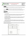
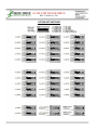
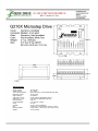
G210X STEP MOTOR DRIVE
REV 5: March 25, 2011
Thank you for purchasing the G210X drive. The G210X microstep drive is warranted to be free of manufacturing defects for 1
year from the date of purchase. Also anyone who is dissatisfied with it or is unable to make it work will be cheerfully refunded the
purchase price if the G210X is returned within 15 days of the purchase date.
PLEASE READ FIRST BEFORE USING THE G210X
Before beginning, be sure to have a suitable step motor, a DC power supply suitable for the motor and a current set resistor. The
motor’s rated phase current must be between 0 Amps and 7 Amps. The power supply voltage must be between 4 times and 20
times the motor’s rated voltage. The current set resistor may be a 1/4 Watt, 5% part. Finally have a STEP and DIRECTION pulse
source available.
DIFFERENCES BETWEEN THE G210X AND G210
The G210X is 100% backwards compatible with the G201 and G210. It has several new features and performance
enhancements:
1.)
2.)
3.)
4.)
5.)
6.)
7.)
8.)
STEP and DIRECTION is +3.3VDC and +5VDC compatible at 2.5mA
Recirculate mode during STANDBY greatly reduces motor heating while stopped
No external 470uF capacitor needed
Power-on RESET
Direction is clocked in on the active step pulse edge
No current set resistor required in lieu of DIP switch settings
Low motor heating while stopped
Universal step and direction COMMON
G210X TERMINAL WIRING
The G210X uses a 2-piece modular main connector. The connector is split in two pieces; terminals 1 through 6 (power supply and
motor leads) and terminals 7 through 12 (control interface). Each can be removed separately by pulling the connector body
upwards and off of the mating header pins on the G210X. The connectors must initially be removed to mount the G210X to a
heatsink or chassis.
TERMINAL 1
Power Ground
Connect the negative (black) lead of your power supply to this terminal.
TERMINAL 2
Power (+)
Connect the positive (red) lead of your power supply to this terminal. It must be between +18VDC to
+80VDC.
TERMINAL 3
Motor Phase A
Connect one end of your “Phase A” motor winding here.
TERMINAL 4
Motor Phase /A
Connect the other end of your “Phase A” motor winding here.
TERMINAL 5
Motor Phase B
Connect one end of your “Phase B” motor winding here.
TERMINAL 6
Motor Phase /B
Connect the other end of your “Phase B” motor winding here.
TERMINAL 7
Disable
This terminal will force the winding currents to zero when shorted to ground (TERMINAL 12).
TERMINAL 8
Direction
Connect the DIRECTION signal to this terminal.
TERMINAL 9
Step
Connect the STEP signal to this terminal.
TERMINAL 10
Common
Connect the controller’s +3.3VDC, +5VDC or GND to this terminal.
1
G210X STEP MOTOR DRIVE
REV 5: March 25, 2011
TERMINAL 11
Current Set (OPTIONAL)
Connect one end of your current set resistor to this terminal.
TERMINAL 12
Current Set (OPTIONAL)
Connect the other end of your current set resistor to this terminal.
POWER SUPPLY HOOKUP
TERMINAL 1
Power Ground
Connect the power supply ground to term.1
TERMINAL 2
Power (+)
Connect the power supply “+” to this terminal
The power supply voltage must be between 18 VDC and 80 VDC. The maximum power supply current required is 67% of the
motor’s rated phase current. An unregulated power supply may be used as long as the voltage stays between the limits; keep the
ripple voltage to 10% or less for best results. The drive has a 2 second power-on reset time before the motor is energized.
CAUTION! Power supply voltage in excess of 80 VDC will damage the G210X.
CAUTION! Never put a switch on the DC side of the power supply! This will damage, if not destroy, your drive!
The choice of power supply voltage depends on the high speed performance required of the motor; doubling the voltage doubles
the motor’s high speed power. In all cases the power supply voltage should be no less than 4 times or no more than 25 times the
motor’s rated voltage. The motor may not run as smoothly as possible if the power supply voltage is less than 4 times the motor’s
rated voltage. A power supply voltage greater than 25 times the motor’s rated voltage will overheat and damage the motor, even if
it is not turning. Motor winding inductance should be 500uH or greater, but generally no more than 7mH.
A more accurate calculation of power supply voltage is to find your motor’s inductance, and put it into the following equation.
32 * (√mH inductance) = Power Supply Voltage
If your motor has 2mH of inductance, the equation would look as follows.
32 * (√2) = 45.12V
MOTOR CONNECTION
TERMINAL 3
Phase A
Connect one motor winding to this terminal
TERMINAL 4
Phase /A
Connect the other end of the winding to this terminal
TERMINAL 5
Phase B
Connect the other motor winding to this terminal
TERMINAL 6
Phase /B
Connect the other end of the winding to this terminal
Connect one motor winding to terminals 3 and 4. Connect the other winding to terminals 5 and 6. Turn the power supply off when
connecting or disconnecting the motor. If the motor turns in the wrong direction, reverse the motor winding connections to
terminals 3 and 4.
CAUTION! Do not short the motor leads to each other or to ground; damage will result to the G210X.
4-wire, 6-wire and 8-wire motor may be used. When 6-wire motors are used, they may be connected in half winding or full
winding. This is equivalent to an 8-wire motor connected in parallel or series. If a motor is connected in series or full winding, the
motor’s phase current rating is half of its parallel or unipolar rating. The choice depends on the high-speed performance required;
a parallel-connected motor will provide twice the power of a series-connected motor at the same power supply voltage.
2
G210X STEP MOTOR DRIVE
REV 5: March 25, 2011
DISABLE PIN
TERMINAL 7
Disable
This terminal will force the winding currents to zero when shorted to ground (TERMINAL 12).
Shorting this input to ground (term. 7 to 12) forces winding currents to zero and stops all output switching activity. The G210X will
continue totalizing step and direction inputs if any are sent. The power supply current drops to less than 15mA. The motor will
return to its original position when the disable input is released if no step pulses have been sent and the motor has not been
moved more than 2 full steps.
STEP AND DIRECTION INPUTS
TERMINAL 8
Direction
Connect the DIRECTION line to this terminal.
TERMINAL 9
Step
Connect the STEP line to this terminal.
TERMINAL 10
Common
Connect the controller’s +3.3VDC, +5VDC or GND to this terminal.
These inputs are optically isolated from the rest of the drive. Terminal 10 is the common connection for the opto-isolators and
must be connected to the +3.3VDC, +5VDC or GND of your indexer or pulse generator.
These inputs are meant to be driven by 3.3V to 5.5V logic capable of sourcing or sinking 2.5mA of current. The minimum logic “0”
time is .5uS while the minimum logic “1” time is 3uS. Microstepping occurs on the falling edge of the step input when COMMON is
a positive voltage and on the rising edge when COMMON is connected to GND.
CURRENT SET RESISTOR (OPTIONAL)
TERMINAL 11
Current Set (OPTIONAL)
Connect the current set resistor to this terminal.
TERMINAL 12
Current Set (OPTIONAL)
Connect the other end of the current set resistor to this terminal.
DIP Switches 1, 2, 3, 4, and 5 must be set to ON if an external current set resistor is used.
This input programs the G210X’s current output to the motor windings. The G210X will accommodate motor winding currents
from 0A to 7A when using an external current set resistor. Use the following equation to calculate the value, (in kilo-ohms) of the
current set resistor:
R (in kilo-ohms) = 47 * I / (7 – I)
Shown are the current set resistor values for motor current in .5A increments.
1.0A
1.5A
2.0A
2.5A
3.0A
3.5A
4.0A
4.5A
5.0A
5.5A
6.0A
6.5A
7.0A
–
–
–
–
–
–
–
–
–
–
–
–
–
7.5K 5% 1/4W
13K 5% 1/4W
18K 5% 1/4W
27K 5% 1/4W
36K 5% 1/4W
47K 5% 1/4W
62K 5% 1/4W
82K 5% 1/4W
120K 5% 1/4W
180K 5% 1/4W
270K 5% 1/4W
620K 5% 1/4W
OPEN 5% 1/4W
3
G210X STEP MOTOR DRIVE
REV 5: March 25, 2011
HEATSINKING
The G210X needs heatsinking for current settings greater than 3 amps. The case temperature (measured on the bottom plate)
should not exceed 70 degrees C, and for best life should be kept to 50 degrees or less. Use heatsink compound between the
G210X and the heatsink.
CAUTION! Current settings above 3 Amps without a heatsink will result in damage to the G210X.
The drive must be heatsinked to a piece of aluminum, preferably with fins and a fan to increase heat dissipation and surface area.
Do not screw the drives directly to the door of your control cabinet, as this will typically not provide adequate heatsinking
properties.
OPTION SET SWITCH
The G210X has 3 settable options which are set via the 10 position DIP switch (visible through the aluminum cover). These
options are:
1.)
Current Set Switches
The current can be set in 0.2A increments using the onboard DIP switch positions SW1, SW2, SW3, SW4, and SW5 or with
a current set resistor. If you are using the DIP switch method, be sure to have nothing connected in TERMINALS 11 and 12;
if you are using a current set resistor be sure to set SW1, SW2, SW3, SW4 and SW5 to the “ON” position.
2.)
Automatic Current Standby
The G210X reduces motor phase current to 50% of the set value when the motor is stopped. This can reduce motor heating
up to 4-fold while the motor is not moving. If enabled, this reduction occurs 1 second after the last step pulse is sent to the
drive. Full current is restored immediately upon resumption of step pulses. SW9 enables this function when “ON” and
disables this function when “OFF”.
3.)
NEMA-34 and NEMA-42 Motor
Use this option if the drive is to be used with NEMA-34 and NEMA-42 size motors. This option adjusts the midband
compensation circuit for optimum performance when using a NEMA-34 and NEMA-42 motors. SW10 enables this function
when “OFF” and disables this function when “ON”. SW10 should be “ON” when used with NEMA-17 and NEMA-23 motors.
ADJUSTING MICROSTEP RESOLUTION
The G210X has an onboard step pulse multiplier called the G901X that allows the drive to operate in full step, half step, 5
microstep and 10 microstep modes. The G901X uses a 2mm jumper block and two jumpers to set the resolution. The jumper
block can be found by using the diagram below:
4
G210X STEP MOTOR DRIVE
REV 5: March 25, 2011
Once the jumpers have been located they may be set according to the diagram below. Please note that the four pins closest to
the optoisolator are unconnected and can be used as jumper storage. It is recommended that needle nose pliers or tweezers be
used to adjust the jumper settings. The power to the G210X must be turned off before any adjustment is to be made on the step
pulse multiplier.
METHOD OF OPERATION FOR STEP PULSE MULTIPLIER:
The G901X step pulse multiplier still allows all of the benefits of microstepping at low speeds and full stepping at high speeds that
the G201X has. The step pulse multiplier works by outputting a set number of pulses to the main motor control board it is
attached to, which is the G201X in the case of the G210X.
If the step pulse multiplier is set to full stepping mode it will output ten microsteps for every pulse it receives on its input; as far as
the base drive is concerned, it is always microstepping at its normal rate. This means that the drive will continue to morph to full
step at higher speeds to allow the highest possible torque from the motor.
RESTORING FACTORY DEFAULTS
To restore the G210X to the factory settings set the trimpot to the 11 o’clock position and set SW1-SW10 to “ON”.
DISCLAIMER
CERTAIN APPLICATIONS USING POWER PRODUCTS MAY INVOLVE POTENTIAL RISKS OF DEATH, PERSONAL INJURY
OR SEVERE DAMAGE TO PROPERTY. GECKODRIVE INC. PRODUCTS ARE NOT DESIGNED, AUTHORIZED OR
WARRANTED TO BE SUITABLE FOR USE IN LIFE-SUPPORT DEVICES OR OTHER CRITICAL APPLICATIONS. INCLUSION
OF GECKODRIVE INC. PRODUCTS IN SUCH APPLICATIONS IS UNDERSTOOD TO BE FULLY AT THE PURCHASER’S
OWN RISK
In order to minimize risks associated with the purchaser’s application, adequate design and operating safeguards must be
provided by the purchaser to minimize inherent or procedural hazards. GECKODRIVE INC. assumes no liability for applications
assistance or the purchaser’s product design. GECKODRIVE INC. does not warrant or represent that any license, either express
or implied, is granted under any patent right, copyright or other intellectual property right of GECKODRIVE INC.
5
G210X STEP MOTOR DRIVE
REV 5: March 25, 2011
OPTION SET SWITCHES
6
G210X STEP MOTOR DRIVE
REV 5: March 25, 2011
SPECIFICATIONS
Supply Voltage:
Phase Current:
Auto Current Reduction:
Quiescent Current:
Step Frequency:
Step Pulse “0” Time:
Step Pulse “1” Time:
Direction Setup:
Power Dissipation:
Temp:
Humidity:
Size:
Mounting Pattern:
Weight:
18 to 80 VDC
0 to 7 Amps
50% of set current, 1 second after last step pulse
15 mA or less
0 to 300 kHz
0.5 uS minimum (optoisolator LED on)
3 uS minimum (optoisolator LED off)
0 uS min
1 to 13 W (0 to 7 Amps)
0 to 70 C
0 to 95 % (non-condensing)
2.5”W, 2.5”D, .85”H (63.5mm, 63.5mm, 21.5mm)
4 6-32 screws, 1.75” by 2.375” (44.5 mm, 60 mm)
3.6 oz. (100 gm)
7