1
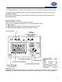
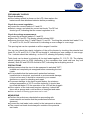
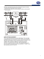
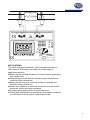
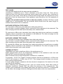
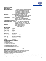
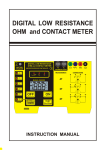
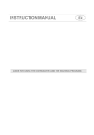
www.pce-industrial-needs.com
Tursdale Technical Services Ltd
Unit N12B
Tursdale Business Park
Co. Durham
DH6 5PG
United Kingdom
Phone: +44 ( 0 ) 191 377 3398
Fax: +44 ( 0 ) 191 377 3357
[email protected]
http://www.industrial-needs.com/
DIGITAL MILLI-OHMMETER
PCE-MO 2002
INSTRUCTION MANUAL
[email protected]
DESCRIPTION
PAGE
SAFETY RULES....................................................
GENERAL DESCRIPTION....................................
FRONT PANEL LAYOUT.......................................
PREPARATION FOR USE....................................
PRELIMINARY CHECKS......................................
PRECAUTIONS.....................................................
MEASURING.........................................................
SIMPLIFIED MEASUREMENT..............................
APPLICATIONS.....................................................
TEST LEADS.........................................................
THERMAL EFFECTS............................................
FUSES REPLACEMENT.......................................
INPUT LIMITS & PROTECTIONS.........................
SPECIFICATIONS.................................................
SPARES & ACCESSORIES..................................
LIMITED WARRANTY...........................................
CLEANING & STORAGE......................................
BATTERY & FUSE REPLACEMENT.....................
01
02-03
04
05
05
06
07
08
09
10
11
12
13
14
15
15
16
16
2
[email protected]
SAFETY RULES
The meter has been designed with safety in mind. However, no
design can completely protect against incorrect use. Electrical
circuits are dangerous and lethal through lack of caution or poor safety practice. The
following rules should reduce the danger
Read the User's manual carefully and completely before using
the instrument. Fully understand the instructions before using
this product. Follow the instructions for every test. Take all the
necessary precautions. Do not exceed the limits of this
instrument.
The circuit to be tested must be de-energised and isolated before
connections are made to it.
Do not use test leads, probes or crocodiles/aligators clips that
are dirty, damaged or have broken or cracked insulation. Such
accessories should be removed and repaired Immediately.
Always disconnect the test leads before replacing any fuse
Always replace the fuse with the type specified and ensure that
they are correctly fitted.
Double check the switch settings and leads connections before
measuring. Make a sketch to ensure proper operation and
principle of measurement is correct and well understood.
Do not touch any exposed wiring, connections or other "live"
parts of an electrical circuit. If in doubt, check the circuit first for
voltage before touching it.
This instrument should only be used by a competent,
suitably trained person which understand fully this test &
measurement procedure.
Warning, risk of electric shock.
Caution, refer to this manual before using the Meter.
3
[email protected]
GENERAL DESCRIPTION
The meter digital milli-ohmmeter is a battery operated instrument wich supply a low current
to the circuit under test, with which, stable, accurate measurement of low resistance can be
made, still, over a wide range of values.
Resolution on the lowest range is 100?ohm and on the highest range, 1 ohm.
The meter has 5 measuring ranges, from 200.0milli-ohm to 2000 ohms.
Measurements are displayed on a 3?digit custom liquid crystal display with large digits.
This instrument is powered from batteries only ( alkaline or rechargeable equivalent).
It has a regulated DC constant current source with current of 1mA 10mA and 100mA.
The instrument supply that current to the resistance being measured through the C1 and C2
terminals (C1 being +, C2 being -).
The voltage drop across the resistance under test is measured by the potential terminals P1
and P2 (P1 being +, P2 being -).
Should the current regulation drops out, the RC Led will lit, indicating that the resistance in
the current circuit is too high. (Lowering the current by selecting a higher resistance range
can solve the regulation.)
Should the RP Led lit, that mean that the voltage measured on the resistance is too high,
and therefore over-range.
The resistance is measured precisely when the RP and RC Leds do not lit. If anyone of
these leds lit, then the measurement can be inaccurate.
The meter has a built-in custom 3?digit liquid crystal display can be viewed in most lightning
conditions. This display indicates the differences conditions (Hold, m, buzzer, polarity
condition of load, + or -, automatic decimal point change).
The ranges are selected by a 5 position rotary switch, and a test is initiated by pressing the
ON push-button.
The instrument takes measurements for 10 seconds if the "ON"
"TEST re" preventative" button is depressed for less than 2 seconds. If the same push button
is pressed for more than 3 seconds, the test will carry on for 60 seconds.
The tester switch "OFF" completely when the rotary switch is in the "OFF" position.
The tester "Hold" the last reading before stopping the test.
The tester is fuse protected and has a crowbar between C1 and C2.
This crowbar is activated by voltage. If the voltage is too high, that crowbar will blow the fuse
automatically to interrupt the circuit.
4
[email protected]
The voltage between P1 and P2 is also protected for over voltage but does not have a fuse.
The tester has a temperature shut down. The temperature sensing is done on the current
regulation transistor.
Should this over-temperature let lit, allow the instrument to cool down for a while before
proceeding further.
FRONT PANEL LAYOUT
If NO TEST LED lit, the current source is stopped.
NO
Over Temperature indicator. Lit = Over-temperature or test
TEST
stopped.
R
Resistance between the current leads too high (fuse!).
R
Resistance between the potential leads too high.
P
C
Current Injection
Terminals
C1
Potential Injection
Terminals
P2
C2
P1
MAX. DC20V
MICROPROCESSOR CONTROLLED
HOLD
M AX
M IN
AUTO-HOLD
Te s t C u rre n t R an g e
1 mA
2000 Ω
1 0m A
2 00 .0 Ω
1 0m A
2 0.0 0 Ω
2000mΩ
1 00 m A
1 00 m A
2 00 .0 m Ω
NO
TEST
RP
RC
2000
200.0
20.00
2000m
200.0m
OFF
EnerSave TM
TES T R P
ON
y Sh o rt Test d u ratio n if TE ST
i s dep ressed fo r less th an
2S ec.
y Lo n g Test D urati on if T E ST
i s d ep ressed fo r mo re t han
3S ec.
-4PREPARATION
FOR
Current/Range Table
Start/Stop Test USE
Liquid Crystal Display
When unpacked, the
tester
should
be
Rotary Selector Switch
inspected for any visible
Meet LVD & EMC
signs of damage, and the
requirements
preliminary
checks
described in the
user's manual should be performed to ensure that it is operating correctly. If there is any sign
of damage, or if the instrument does not operate correctly, return it to your nearest supplier.
5
[email protected]
PRELIMINARY CHECKS
Check the battery
If the battery symbol is shown on the LCD, then replace the
batteries with new alkalines batteries before proceeding.
Check the current regulation:
Connect the current leads to C1 and C2.
Select a range, and short the current test leads. The RC led
should go off, indicating that the current regulation is ok.
Check the voltage measurement:
Connect the potential leads to P1 and P2.
Short the P1 and P2. The display should indicate 0000.
Remove the short from P1 and P2and C1 and C2. Touching the potential test leads P1 to
C1 and P2 to C2, the RP led should lit, indicating an over-voltage or over-range.
This proving test can be repeated on all the ranges if need be.
You can also check the polarity indication of the milli-voltmeter by touching the potential test
leads P1 to C2 and P2 to C1, the RP led should lit, indicating an over-voltage or over-range.
The - indicator should be indicating - on the LCD, showing the polarity change.
Total check can be done by shorting all the test leads together C1, C2, P1, P2. The display
should indicate close to 0000 (depending of the crocodiles clips used and how they are
shorted). Both RC and RP LED should be OFF, indicating that everything work ok.
PRECAUTIONS
Always ensure that the circuit to be measured is switched "OFF",
isolated and completely de-energised before connecting the test
Leads.
If it is probable that the instrument's protection has been
impaired due to electrical, mechanical or environmental damage,
it must not be used. It should be returned to your nearest
distributor or agent for checking and repair.
To prevent damage to the liquid crystal display, the minimum
storage temperature of -20°C must be observed. It should also
be noted that below 0°C the operation of the LCD will be sluggish
If the exterior of the instrument requires cleaning, it should be
done with a sponge and a mild solution of detergent and water.
Other mechanical cleaning agents must not be used.
MEASURING
Perform the preliminary checks before proceeding with
measurement and ensure that the precautions listed are
observed.
Connect the test leads (color coded) to the instrument as shown.
The current test leads must always be outside of the potential
test leads.
6
[email protected]
Please note that the shorter the potential test leads, the better
long potential test leads will pick up noise.
Screened test leads are recommended for better environmental
noise rejection.
MAX. DC20V
2000
HOLD
MAX
MIN
2000m
200.0m
2000
200.0
20.00
2000m
200.0m
EnerSave TM
SIMPLIFIED MEASUREMENT
The 4 wires measurement has many advantages. The errors due
to the resistance of the test leads and the contacts as well as RA
and RB are eliminated. However, in some cases, for example when
using the high resistance range (2000 ohms) the four wires
method is not necessary to still have a good percentage of
accuracy (compared to the full scale). The simplified method of
two wires can be used without too much problems. C1 and P1 can
be shorted as well as C2 and P2.
7
[email protected]
RX
C1
P1
P2
C2
MAX. DC20V
MICROPROCESSOR CONTROLLED
HOLD
MAX
MIN
AUTO-HOLD
Test Current Range
1mA
2000 Ω
10mA
200.0 Ω
10mA
20.00 Ω
2000m Ω
100mA
100mA
200.0mΩ
NO
TEST
RP
RC
2000
200.0
20.00
2000m
200.0m
OFF
EnerSaveTM
TEST R P
ON
y Sh ort Test du ration if TEST
is d epressed for less than
2Sec.
y L ong Test Duratio n if TEST
is depressed for mo re than
3Sec.
APPLICATIONS
The meter Digital milli-ohmmeter, with its measuring range of
100u ohms to 2000 ohms, is suitable for a wide range of
applications such as:
Measuring the winding resistance of electric motors, generators
And transformers.
Bond testing in mines, aircraft, railways, ships, domestic and
industrial wiring installations.
Measuring the ring main continuity testing in industrial and
domestic wiring installations.
Measuring resistance in electronic equipment such as shunts,
pcb tracks, switch and relay resistance.
Checking compression joints on overheads lines.
Testing and maintenance of switchboard /sub-station equipment
on such items as fuses, joints, contacts and bonds.
8
[email protected]
TEST LEADS
The test leads supplied with the instrument are suitable for
connecting to conductors up to 17mm in diameter or bus bars 17mm tick. There will be,
instances where the item being measured require larger jaws, and the user is advised to
make up his own leads. There will be occasions when longer leads are required due to the
geometry of the item being tested. Some guidance notes should as sit in the assembly of
such leads:
Length of the potential leads should be as short as possible. Insulated 16/0.2mm, tinned
copper wire is recommended. The two potential leads should have the same length to
minimise inaccuracies due to unbalance.
SUPPLIED POTENTIAL TEST LEADS
P1+ test lead is of Red color, shrouded, 4mm safety plug which at
one end have a crocodile (alligator) clip for connection to the resistance to be measured. The
other end plugs into the meter (4mm shrouded) color coded sockets.
P2- test lead is of Blue color, shrouded, 4mm safety plug which at one end have a crocodile
(alligator) clip for connection to the resistance to be measured. The other end plugs into the
meter (4mm shrouded) color coded sockets.
SUPPLIED CURRENT TEST LEADS
C1+ test lead is of Green color, shrouded, 4mm safety plug which at
one end have a crocodile (alligator) clip for connection to the resistance to be measured. The
other end plugs into the meter (4mm shrouded) color coded sockets.
C2- test lead is of Black color, shrouded, 4mm safety plug which at one end have a crocodile
(alligator) clip for connection to the resistance to be measured. The other end plugs into the
meter (4mm shrouded) color coded sockets.
THERMAL EFFECTS
Temperature can have a significant effect on the performance of a
digital milli-ohmmeter due to the temperature coefficient of the resistance under test and
thermal EMF's across the dissimilar conductors.
Most conductors have a large temperature coefficient of resistance.
For example:0.4%/°C for copper. A copper conductor that has a resistance of 10.00m ohm
at 20°C will increase to 10.40m ohm at 30°C. This change should be taken into account
when making measurements.
A current going through a resistance will also elevate its temperature. So duration of the test
can change the resistance.
When measuring the resistance of item, such as current shunts, which have joints of
dissimilar conductors, thermal EMF can affect the accuracy of the measurement. This
condition can be detected if the reading alters when the leads are reversed. To compensate
for this effect, the average of the two readings should be taken as the true measurement.
9
[email protected]
FUSES REPLACEMENT
There are three fuses:
Power Supply Fuse
The power supply fuse is situated under the tester. Open the
battery compartment, and replace the fuse with the same type
(1.5A, >24V, Slow Blow)
Current Circuit Fuse
Fuse protection is provided on the current terminals.
This fuse is situated under the Printed Circuit Board. To access
it, you need to unscrew the four mounting screws which are
holding the font panel. Two os these screws are located under
the foots, and the two others are located inside the battery
compartment.
The fuse is automatically blow by the crowbar, should voltage be
present on the resistance under test. This is to prevent damage
to the instrument.
It is indicative of this fuse being blown is the RC Led stays "on".
(HBC, 1A, 250Vac, Slow Blow)
Potential Circuit Fuse
Fuse protection is provided on the potential terminals.
This fuse is situated under the Printed Circuit Board. To access
it, you need to unscrew the four mounting screws which are
holding the font panel. Two os these screws are located under
the foots, and the two others are located inside the battery
compartment.
The fuse is automatically blow by the crowbar, should voltage be
present on the resistance under test. This is to prevent damage
to the instrument.
If the preliminary tests does not lit R P this is indicative of this fuse
being blown. (HBC, 0.5A, 250Vac, Slow Blow)
INPUT LIMITS & PROTECTIONS
The maximum continuous voltage which can be applied across the
potential and current leads is around 10.7V. Applying more than that voltage will
automatically blow their respective fuses.
However, the crowbar trigger can be factory adjusted for your application.
We have specially selected that method to stop damaging the instrument, should it be
misused.
10
[email protected]
SPECIFICATIONS
ELECTRICAL
Measuring Ranges
0-200.0m ohms in steps of 100uohm
0-2000m ohms in steps of 1m ohm
0-20.00 ohms in steps of 10m ohm
0-200.0 ohms in steps of 100m ohm
0-2000 ohms in steps of 1 ohm
Accuracy
±0.5% of reading ±2 digits over the
Operating temperature range, -15°C to
+55°C, with the supplied test leads.
Test Current
1mA => 2000 ohms range.
10mA => 200 / 20 ohms ranges.
100mA => 2000m / 200m ohm ranges.
Test Current Accuracy ±0.1%
Protection Fuses
Supply = 1.5A, HBC, 5 x 20mm, DIN
Current = 1A, HBC, 5 x 20mm, DIN
Voltage = 0.5A, HBC, 5 x 20mm, DIN
SAFETY
LVD BS EN 61010-1
EMC BS EN 50081-1
BS EN 50082-1
MECHANICAL
Case Height :
110mm
Case Width :
250mm
Case Depth :
190mm
Bump Test
:
IEC68-2-29
Vibration Test:
IEC1010, clause 8.3
:
IEC1010, clause 8.4
Impact Test :
IEC1010, Clause 8.2
Drop Test
Weight
: 1.542kg
Rated environmental conditions
(1).Indoor Use
(2).Pollution Degree 2.
(3).Altitude up to 2000 meter.
(4).Relative humidity 80% max.
(5).Ambient temperature 0°C ~40°C.
-14SPARES & ACCESSORIES
At the date of printing this user's manual, accessories were not yet
available. Please contact the factory for further information.
Spares are available from your nearest distributor.
LIMITED WARRANTY
We warrant the product manufactured by us to be free from defective material or factory workmanship
and agree to repair or replace this product which, under normal use and service, disclose the defect
11
[email protected]
to be the fault of our manufacturing, with no charge for parts and service. If we are unable to repair or
replace this product, we will make a full refund of the purchase price. Consult the user's manual for
proper instruction regarding use of this instrument. Our obligation under this warranty is limited to
repairing, replacing or making refund of this test equipment which proves to be defective within forty
eight months from the date of original purchase.
This warranty does not apply to any of our products which have been repaired or altered by
unauthorized persons in any way so as, in our sole judgment, to injure their stability or reliability, or
which have been subject to misuse, abuse, misapplication, negligence or accident or which have had
the serial numbers altered, defaced or removed.
Accessories, not of our manufacture used with this product, are not covered by this warranty.
All warranties implied by law are hereby limited to a period of forty eight months, and the provisions of
the warranty are expressly in lieu of any other warranties expressed or implied.
The purchaser agrees to assume all liability for any damages or bodily injury which may result from
the use or misuse of the product by the purchaser, or it's user, his employees, or others, and the
remedies provided for in this warranty are expressly in lieu of any other liability we may have including
incidental or consequential damages.
We reserve the right to discontinue models at any time, or change specification, price or design,
without notice and without incurring any obligation.
-15CLEANING & STORAGE
Periodically wipe the case with a damp cloth and detergent:do not use abrasives or
solvents.
If the meter is not to be used for periods of longer than 60 days, remove the batteries and
store them separately.
BATTERY & FUSE REPLACEMENT
Battery Replacement
yThe tester continuously monitors the battery voltage and
indicates when the batteries need to be replaced.
yThe tester's battery is situated under the tester.
yDisconnect the test leads from the instrument and remove the
battery cover and the batteries.
yReplace with eight 1.5V AA pen light batteries, taking care to
observe correct polarity.
yAlkaline batteries are recommended.
yReplace battery holder and the battery cover.
Fuse Replacement
yThe fuse is located under the battery holder.
yTo replace fuse, open the battery cover. Then remove and
replace the fuse located under the battery holder.
yOnly replace with same fuse specification. (250mA)
CAT IV -
Is for measurements performed at the source of the lowvoltage installation.
12
[email protected]
CAT II CAT II -
Is for measurements performed in the building Installation
Is for measurements performed on circuits directly
connected to the low-voltage installation.
CAT I - Is for measurements performed on circuits not directly
connected to mains.
Due to our policy of constant improvement and development, we reserve the right to change specifications
without notice.
In this direction will find a vision of the measurement technique:
http://www.industrial-needs.com/measuring-instruments.htm
NOTE: "This instrument doesn’t have ATEX protection, so it should not be used in potentially explosive
atmospheres (powder, flammable gases)."
13