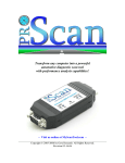
1
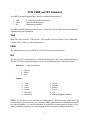
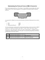
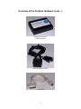
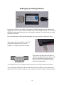
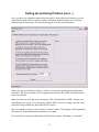
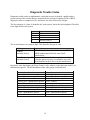
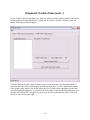
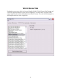
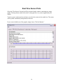
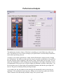
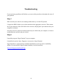
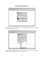
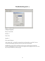
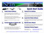
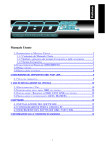
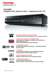
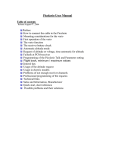
ProScan v1.4 User's Manual
http://www.MyScanTool.com
Table of Contents
A thank you note from the author
3
OBD-II background information
4
VPW, PWM, and ISO explained
5
Determining the protocol from an OBD-II connector
6
Overview of the ProScan hardware
7,8
Installing the ProScan software
9
Setting up and using ProScan
10,11
Diagnostic Trouble Codes (DTC)
12-14
Vehicle Sensor Data
15
Real-Time Sensor Plots
16
Performance Analysis
17
FAQ (USB, upgrades, palm support, etc)
18
Troubleshooting
19-22
Legal
23
2
Thank You
Thank you for purchasing the ProScan automotive diagnostic and performance analysis
tool. The beauty of this tool is that it is implemented entirely in software, thus making the cost
very cheap compared to sophisticated electronic scan tools that are usually limited in features by
their hardware design. ProScan is an advanced vehicle analysis tool that can easily be upgraded
with better features, and the possibilities are virtually endless!
My goal is to turn ProScan into the best all-around automotive analysis tool in the world.
In order for this to happen, I need to hear your feedback. Please contact me and let me know
exactly how you feel about ProScan. Tell me about the features you like and dislike, and describe
features that you would like to see implemented. My promise to you is that I will work my
hardest to transform ProScan into the ultimate vehicle analysis tool for your specific needs.
Thank you!
David A. Gore
[email protected]
3
OBD-II Background Information
All US vehicles from 1996 and up are required to be OBD-II compliant. OBD stands for On
Board Diagnostics, and the Roman numeral for two indicates that it is the second generation of
the OBD protocol.
All modern vehicles are controlled primarily by an on-board computer. The computer monitors
various sensors and uses the collected data to control the state of the vehicle. If a potential
problem is found by one of the sensor readings, the computer will store a Diagnostic Trouble
Code (DTC) in memory. When a DTC is stored, the vehicle’s check engine light will illuminate.
Then the problem can be easily discovered by using an OBD scan tool to read the stored DTC(s).
Once the problem is identified it can be repaired, and then the OBD scan tool can be used to
clear the DTC(s) from memory, thus resetting the check engine light.
ProScan provides a full-featured OBD-II scan tool and a whole lot more!
4
VPW, PWM, and ISO Explained
The OBD-II standard supports three different communication protocols:
1. VPW
2. PWM
3. ISO
Variable Pulse Width Modulation
Pulse Width Modulation
International Standard
The OBD standard remains the same on every vehicle, but there are three different methods for
communicating the information.
VPW
Most GM vehicles use the VPW protocol. This includes Chevrolet, Pontiac, GMC, Oldsmobile,
Cadillac, Buick, and a few other manufacturers.
PWM
The PWM protocol is used primarily by Ford and a few other manufacturers.
ISO
The ISO protocol is used primarily by European manufacturers, but is also used domestically by
Chrysler. The following list illustrates some of the manufacturers that use the ISO protocol:
Domestics
•
•
•
(Chrysler products)
Chrysler
Dodge
Jeep
Imports
•
•
•
•
•
•
•
•
•
•
•
•
Acura
Audi
BMW
Honda
Mercedes
Mitsubishi
Nissan
Porsche
Subaru
Toyota
VW
Nearly all import vehicles!
NOTE: The lists above are not intended to be comprehensive. Before ordering, please verify the
communication protocol used on your vehicle by asking a professional. Your local dealer should
have this information. You can also determine the protocol by analyzing the pins found on your
vehicle’s OBD-II connector. (See: Determining the Protocol from an OBD-II Connector)
5
Determining the Protocol from an OBD-II Connector
Every vehicle manufactured since 1996 will have a 16-pin OBD-II connector that can be found
within 1 meter (3 feet) of the steering wheel. The image below illustrates what the connector
looks like.
As a general rule of thumb, you can use the following to determine which protocol your vehicle
uses:
•
•
•
GM
Ford
European and Chrysler
VPW
PWM
ISO
You can also determine which protocol is implemented by taking a look at the vehicle’s OBD-II
connector. All vehicles are required to have pins 4, 5, and 16. Pin 4 is the vehicle’s chassis
ground, pin 5 is the signal ground, and pin 16 is positive from the battery. In addition to pins 4,
5, and 16, the connector will have one or more pins. You can use the pin positions to determine
which protocol is used on the vehicle.
PWM
Must have the following pins: 4, 5, 16, 2, 10
VPW
Must have the following pins: 4, 5, 16, 2 (Note: Not pin 10)
ISO
Must have the following pins: 4, 5, 16, 7 (Note: Pin 15 is optional)
6
Overview of the ProScan Hardware
Each ProScan kit includes the following:
Qty
Description
1
OBD-II Interface Cable
This cable attaches to the vehicle’s 16-pin OBD-II connector. The other end
attaches to the appropriate electrical converter.
1-3
Electrical Converter
The electrical converter is a small black box with connectors on opposite ends.
The converter’s job is to translate the vehicles OBD-II signal into a signal that is
usable by a computer. There are three different OBD-II signals (VPW, PWM,
and ISO) so there are three different electrical converters.
When ordering a ProScan kit, you specify which converter(s) you need.
1
Serial Cable
This cable attaches to the other end of the converter being used. The opposite end
of the cable goes to the serial port of your computer.
1
ProScan CD-ROM
The CD contains the following:
•
•
•
•
ProScan software
.NET Framework
User’s manual
Adobe Acrobat Reader
The ProScan software is developed using Microsoft’s new .NET technology.
This means that the .NET Framework must be installed on the computer you
intend to use ProScan. Windows XP already has the .NET Framework installed,
but it may need to be upgraded. Users of earlier versions of Windows will need
to install the .NET Framework. It can be downloaded free of charge from
Microsoft, but it is also included on the CD.
The user’s manual is a PDF file which requires Adobe Acrobat Reader. This
prerequisite can also be installed directly from the CD.
7
Overview of the ProScan Hardware (cont…)
Electrical Converter
(VPW pictured)
OBD-II Interface Cable
Serial Cable
8
Installing the ProScan Software
The ProScan installation program should launch once the CD is inserted. If not, the setup
program is located in the root directory of the CD, and the filename is "setup.exe". Follow the
simple instructions to complete the installation process. When finished, you will have a shortcut
to ProScan on your desktop and on your Start menu.
9
Setting Up and Using ProScan
In order to use ProScan, the vehicle must support the OBD-II standard, and you must use the
appropriate converter (VPW, PWM, or ISO) in order to communicate properly. The converter is
the black box that attaches between the vehicle and the computer. The converter type is clearly
indicated on the label.
First, assemble the two cables and the appropriate converter as shown in the picture above.
Then connect the other end of the serial cable
(on the left in the picture above) to your
computer’s serial port as shown to the right.
Then connect the other end of the OBD-II
cable (on the right in the picture above) to the
vehicle’s under-dash connector (pictured
below). It will be located within 1-meter (3feet) of the steering wheel.
You should now have your computer connected to the vehicle via the cables and converter.
You can go ahead and start the vehicle at this time. (On some vehicles, you can connect and
analyze sensor data without starting the engine, but the key must be turned to the ON position.)
10
Setting Up and Using ProScan (cont…)
Once you have your computer connected to the vehicle via the cables and converter, you can
launch the ProScan software either by double-clicking the desktop shortcut or by selecting
ProScan from the Start menu. ProScan should appear as in the screenshot below.
Before you can use ProScan to analyze a vehicle, you must first go through an initialization
procedure. This process obtains a list of supported sensors from the vehicle and initializes the
electrical converter.
Make sure that you select the correct serial port. This will typically be COM01, but may vary
depending on your setup. If you are using a USB to RS232 converter, simply select the serial
port that is being emulated by the USB to RS232 drivers.
Once everything is ready you may click the “Connect” button. The progress will be updated in
the status box. It should not take more than a few seconds.
If successful, the status bar at the bottom of the ProScan window will display: “Connected.”
11
Diagnostic Trouble Codes
Diagnostic trouble codes are alphanumeric codes that are used to identify a problem that is
present on any of the systems that are monitored by the on-board computer (PCM). OBD II
diagnostic codes are composed of five characters; one letter followed by 4 digits.
The first character is a letter. It identifies the "main system" where the fault originated. The table
to the right defines each system.
Letter
B
C
P
U
System
Body
Chassis
Powertrain
Network (UART)
The second character is a numeric digit. This identifies the type of code.
Code type
Generic
(normally P0xxx)
Explanation
The definition for the code is defined in the EOBD /
OBDII standard and will be the same for all
manufacturers.
Manufacturer-specific Where manufacturers feel that a code is not available
(normally P1xxx)
within the generic list, they can add their own codes.
The definitions for these are set by the manufacturer.
In general, codes that begin with P0 are Generic codes, whereas codes that begin with P1 are
manufacturer-specific. The full breakdown of the code groups is shown below:
Powertrain codes
P0xxx - Generic
P1xxx - Manufacturer-specific
P2xxx - Generic
P30xx-P33xx - Manufacturer-specific
P34xx-P39xx - Generic
Chassis codes
C0xxx - Generic
C1xxx - Manufacturer-specific
C2xxx - Manufacturer-specific
C3xxx - Generic
Body codes
B0xxx - Generic
B1xxx - Manufacturer-specific
B2xxx - Manufacturer-specific
B3xxx - Generic
Network Communication codes
U0xxx - Generic
U1xxx - Manufacturer-specific
U2xxx - Manufacturer-specific
U3xxx - Generic
12
Diagnostic Trouble Codes (cont…)
The third digit of a DTC defines the specific system or sub-system within the car where the
problem is located:
Third digit
1
2
3
4
5
6
7,8
System or sub-system
Fuel and Air Metering
Fuel and Air Metering (injector circuit malfunction only)
Ignition System or Misfire
Auxiliary Emission Control System
Vehicle Speed Control and Idle Control System
Computer Output Circuits
Transmission
13
Diagnostic Trouble Codes (cont…)
If your vehicle's check engine light is on, then you need to run the ProScan Trouble Codes tool to
find the problem. Simply start ProScan, connect to the vehicle, click the "Trouble Codes" tab,
and the following screen will appear.
Click the "Refresh Trouble Codes" button to request a list of stored codes from the vehicle. If
any codes are found, they will be displayed in the list on the left. To view a detailed description
of the trouble code, simply click on the code in the list. If ProScan has a definition for the code,
it will be displayed. Otherwise, you will need to do an online search for the definition. Once you
find the cause of the DTC and repair it, you need to clear the codes from the vehicle. This will
also reset your check engine light.
14
Vehicle Sensor Data
Reading the sensors on a vehicle is a breeze. Simply click the "Vehicle Sensor Data" button, and
a list of all supported sensors for your vehicle is displayed. To read a sensor, just click on the
sensor in the list and click the "Read the Selected Sensor" button. The value will be displayed in
both English and metric units if applicable.
15
Real-Time Sensor Plots
Select the "Plot Sensors" tab and you'll be presented with a window containing two empty
graphs. The drop-down combo boxes above each graph list every sensor supported by the
vehicle.
To plot a sensor continuously in real-time, just select the sensor in the combo box. The sensor
will be polled continuously and plotted in real-time.
If you want to disable one of the graphs, simply choose "Do Not Monitor.”
16
Performance Analysis
The Performance Analysis feature of ProScan is something you won't find on any other scan
tool! The statistics are very accurate as long as your speed sensor is accurate and you don't have
much wheel spin during your run.
To analyze your vehicle's performance, simply start the Performance Analysis tool by clicking
the “Performance” tab. Make sure that your car is on a level surface and that there is no traffic on
the road. Stop the vehicle completely, and click the "Stage" button when you are ready. You can
ignore the weight and tire radius settings because the horsepower and torque calculations are not
yet implemented. The top two rows of yellow lights will illuminate, and after a short delay (~2s),
the lower three rows of yellow lights will sequentially illuminate and then the green light will
turn on. The goal is to launch perfectly on the green light.
As you make your run, the numbers on the timeslip will automatically show up once they are
calculated. You can abort the run at any time. When you are ready to try again, just click the
"Reset" button to clear the timeslip, and then "Stage" once you are ready.
17
Frequently Asked Questions
1. My laptop does not have a serial port. Does ProScan work with USB?
Yes! Since version 2.0, ProScan has supported USB. In order to use ProScan with
a USB port, you will need to buy a USB to RS232 (serial) converter. You can find
one at any computer store for around $30.
2. Is ProScan available for Palm OS or Windows CE?
ProScan is currently being ported to run on Palm OS. A Palm OS version should
be available in January, 2004.
There are no intentions for Windows CE development at this time.
18
Troubleshooting
If you are having a problem with ProScan, you can use this procedure to determine the cause of
your problem.
Step 1
Make sure that your vehicle is not running and that the key is in the OFF position.
Connect the OBD-II cable to your vehicle and then to the appropriate converter. Then connect
the 25-pin connector of the serial cable to the converter, and plug the 9-pin connector into your
computer's serial port.
Now that you have a physical connection between your vehicle and your computer, it is time to
troubleshoot the converter and your vehicle.
Step 2
Launch the program “HyperTerminal” on your computer.
It should be located at: Start->Programs->Accessories->HyperTerminal
HyperTerminal is a program that is included with Windows, but it may not be installed by
default. If you do not have HyperTerminal installed, it can be found here:
Microsoft Hyperterminal Install Page
19
Troubleshooting (cont…)
When asked for a name for the connection, you can simply enter anything that you wish. On the
left, you can see that I chose "blah".
You will then need to specify that you want to connect via the serial port. This will probably be
COM1 or COM2, depending on your computer configuration.
20
Troubleshooting (cont…)
COM port Properties:
Bits per second: 9600
Data bits: 8
Parity: None
Stop bits: 1
Flow control: Hardware
After clicking "OK", you should be connected to the serial port that you specified. You can
verify this by checking the status bar in the lower left corner of the window.
Anything that you type will be sent directly to the converter via the serial port connection.
Likewise, anything that the converter sends to the computer will be displayed on the screen. You
may or may not be able to see what you type.
21
Troubleshooting (cont…)
Step 3
At this time, turn the vehicle key to the ON position. This will provide power to the converter,
and the converter should echo the name and version number of its internal processor. You should
see something like: "ELM322 v1.1" appear in the HyperTerminal window. If nothing appears,
type: "ATI" and press ENTER. This is a command that will force the converter to identify itself.
If nothing appears, check your cable connections, and verify that you are using the appropriate
converter for your vehicle. Click the "File" menu and choose "New Connection". Repeat the
above procedure, but try a different COM port this time. If you used COM1 the first time, try
COM2 this time. If you don't see any text within a few seconds, type: "ATI" and hit ENTER. If
you still can't get the converter to respond, you can try yet another COM port setting.
Once you have tried all possible COM port settings, you can conclude that the converter is not
functioning properly. This is because either the converter is not working properly or it is not the
appropriate converter for the vehicle. If you purchased more than one converter, you can try the
above process with another converter type.
If you can successfully get the converter to respond and print a message to the screen, then you
can conclude that the cables are attached properly and that the correct converter is being used for
the vehicle.
Step 4
Once you have verified that the converter is attached properly and that it is the correct converter
for the vehicle, you need to verify that the converter can communicate with the vehicle's OBD-II
system.
To verify this, type: "0101" and press ENTER.
You should receive a response such as this: "41 01 81 07 65 04". The numbers will vary, but it
should begin with "41 01". If you received a similar response, then you can conclude that the
hardware is working properly.
If you did not receive a response, or if you received an error message, then the converter is
having problems communicating with your vehicle. This could be because the converter is of the
wrong protocol (VPW, PWM, or ISO), it could be a malfunctioning converter, or it could be a
problem with your vehicle's OBD-II system.
22
Legal
ProScan software is protected by copyright law. Unauthorized reproduction or distribution of
ProScan, or any portion of it, may result in severe civil and criminal penalties.
You should never attempt to use ProScan while operating a moving vehicle. Analysis of a
moving vehicle should only be conducted by a passenger of the vehicle. The performance
analysis features of ProScan are to be used in law-abiding fashion. MyScanTool.com will not be
liable or have any responsibility of any kind for any loss or damage that you incur while using
ProScan to analyze a vehicle.
Copyright © 2004 MyScanTool.com
All rights reserved. No part of this publication may be reproduced, stored in a retrieval system or
transmitted, in any form or by any means, electronic, mechanical, photocopying, recording, or
otherwise, without the prior written permission of MyScanTool.com.
23