1
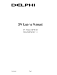
Manual VN0601 ARINC 429 / IO Interface Version 1.1 English Imprint Vector Informatik GmbH Ingersheimer Straße 24 D-70499 Stuttgart The information and data given in this user manual can be changed without prior notice. No part of this manual may be reproduced in any form or by any means without the written permission of the publisher, regardless of which method or which instruments, electronic or mechanical, are used. All technical information, drafts, etc. are liable to law of copyright protection. © Copyright 2015, Vector Informatik GmbH. All rights reserved. Manual VN0601 Contents Contents 1 Introduction 5 1.1 Safety Instructions and Hazard Warnings 6 1.1.1 Proper Use and Intended Purpose 6 1.1.2 Hazards 7 1.1.3 Disclaimer 7 1.2 About this User Manual 8 1.2.1 Certification 8 1.2.2 Warranty 9 1.2.3 Registered Trademarks 9 2 VN0601 Network Interface 10 2.1 Introduction 11 2.2 Accessories 11 2.3 Examples of Usage 12 2.3.1 Analyzing Traffic of Multiple Lines 12 2.3.2 Transmitting and Monitoring 13 2.3.3 In-line Data Modification 14 2.4 Getting Started 15 2.4.1 Step 1: Driver Installation 15 2.4.2 Step 2: Device Installation 15 2.4.3 Step 3: Device Configuration 15 2.5 Device Description 17 2.5.1 D-SUB37 Pin Assignment (ARINC 429) 17 2.5.2 D-SUB9 Pin Assignment (IO) 18 2.5.3 Synchronization 19 2.5.4 LEDs 20 2.5.5 Technical Data 21 3 Common Features 22 3.1 Time Synchronization 23 3.1.1 General Information 23 3.1.2 Software Sync 25 3.1.3 Hardware Sync 26 4 Driver Installation 28 4.1 Vector Driver Setup 29 5 Vector Hardware Configuration © Vector Informatik GmbH 31 Version 1.1 -3- Manual VN0601 Contents 5.1 General Information 32 5.2 Tool Description 33 5.2.1 Introduction 33 5.2.2 Tree View 34 © Vector Informatik GmbH Version 1.1 -4- Manual VN0601 1 Introduction 1 Introduction In this chapter you find the following information: 1.1 Safety Instructions and Hazard Warnings 6 1.1.1 Proper Use and Intended Purpose 6 1.1.2 Hazards 7 1.1.3 Disclaimer 7 1.2 About this User Manual 8 1.2.1 Certification 8 1.2.2 Warranty 9 1.2.3 Registered Trademarks 9 © Vector Informatik GmbH Version 1.1 -5- Manual VN0601 1 Introduction 1.1 Safety Instructions and Hazard Warnings ! Caution: In order to avoid personal injuries and damage to property, you have to read and understand the following safety instructions and hazard warnings prior to installation and use of this interface. Keep this documentation (manual) always near the interface. 1.1.1 Proper Use and Intended Purpose ! Caution: The interface is designed for analyzing, controlling and otherwise influencing control systems and electronic control units. This includes, inter alia, bus systems like CAN, LIN, K- Line, MOST, FlexRay, Ethernet, BroadR- Reach and/or ARINC 429. The interface may only be operated in a closed state. In particular, printed circuits must not be visible. The interface may only be operated (i) according to the instructions and descriptions of this manual; (ii) with the electric power supply designed for the interface, e.g. USB- powered power supply; and (iii) with accessories manufactured or approved by Vector. The interface is exclusively designed for use by skilled personnel as its operation may result in serious personal injuries and damage to property. Therefore, only those persons may operate the interface who (i) have understood the possible effects of the actions which may be caused by the interface; (ii) are specifically trained in the handling with the interface, bus systems and the system intended to be influenced; and (iii) have sufficient experience in using the interface safely. The knowledge necessary for the operation of the interface can be acquired in workshops and internal or external seminars offered by Vector. Additional and interface specific information, such as „Known Issues“, are available in the „Vector KnowledgeBase“ on Vector´s website at www.vector.com. Please consult the „Vector KnowledgeBase“ for updated information prior to the operation of the interface. © Vector Informatik GmbH Version 1.1 -6- Manual VN0601 1 Introduction 1.1.2 Hazards ! Caution: The interface may control and/or otherwise influence the behavior of control systems and electronic control units. Serious hazards for life, body and property may arise, in particular, without limitation, by interventions in safety relevant systems (e.g. by deactivating or otherwise manipulating the engine management, steering, airbag and/or braking system) and/or if the interface is operated in public areas (e.g. public traffic, airspace). Therefore, you must always ensure that the interface is used in a safe manner. This includes, inter alia, the ability to put the system in which the interface is used into a safe state at any time (e.g. by „emergency shutdown“), in particular, without limitation, in the event of errors or hazards. Comply with all safety standards and public regulations which are relevant for the operation of the system. Before you operate the system in public areas, it should be tested on a site which is not accessible to the public and specifically prepared for performing test drives in order to reduce hazards. 1.1.3 Disclaimer ! Caution: Claims based on defects and liability claims against Vector are excluded to the extent damages or errors are caused by improper use of the interface or use not according to its intended purpose. The same applies to damages or errors arising from insufficient training or lack of experience of personnel using the interface. © Vector Informatik GmbH Version 1.1 -7- Manual VN0601 1 Introduction 1.2 About this User Manual Conventions In the two following charts you will find the conventions used in the user manual regarding utilized spellings and symbols. Style bold Utilization Blocks, surface elements, window- and dialog names of the software. Accentuation of warnings and advices. [OK] Push buttons in brackets File|Save Notation for menus and menu entries Microsoft Legally protected proper names and side notes. Source Code Hyperlink <CTRL>+<S> File name and source code. Hyperlinks and references. Notation for shortcuts. Symbol Utilization Here you can obtain supplemental information. ! This symbol calls your attention to warnings. Here you can find additional information. Here is an example that has been prepared for you. Step-by-step instructions provide assistance at these points. Instructions on editing files are found at these points. This symbol warns you not to edit the specified file. 1.2.1 Certification Certified Quality Management System © Vector Informatik GmbH Vector Informatik GmbH has ISO 9001:2008 certification. The ISO standard is a globally recognized standard. Version 1.1 -8- Manual VN0601 1 Introduction 1.2.2 Warranty Restriction of warranty We reserve the right to change the contents of the documentation and the software without notice. Vector Informatik GmbH assumes no liability for correct contents or damages which are resulted from the usage of the documentation. We are grateful for references to mistakes or for suggestions for improvement to be able to offer you even more efficient products in the future. 1.2.3 Registered Trademarks Registered trademarks All trademarks mentioned in this documentation and if necessary third party registered are absolutely subject to the conditions of each valid label right and the rights of particular registered proprietor. All trademarks, trade names or company names are or can be trademarks or registered trademarks of their particular proprietors. All rights which are not expressly allowed are reserved. If an explicit label of trademarks, which are used in this documentation, fails, should not mean that a name is free of third party rights. > Windows, Windows 7, Windows 8.1 are trademarks of the Microsoft Corporation. © Vector Informatik GmbH Version 1.1 -9- Manual VN0601 2 VN0601 Network Interface 2 VN0601 Network Interface In this chapter you find the following information: 2.1 Introduction 11 2.2 Accessories 11 2.3 Examples of Usage 12 2.3.1 Analyzing Traffic of Multiple Lines 12 2.3.2 Transmitting and Monitoring 13 2.3.3 In-line Data Modification 14 2.4 Getting Started 15 2.4.1 Step 1: Driver Installation 15 2.4.2 Step 2: Device Installation 15 2.4.3 Step 3: Device Configuration 15 2.5 Device Description 17 2.5.1 D-SUB37 Pin Assignment (ARINC 429) 17 2.5.2 D-SUB9 Pin Assignment (IO) 18 2.5.3 Synchronization 19 2.5.4 LEDs 20 2.5.5 Technical Data 21 © Vector Informatik GmbH Version 1.1 - 10 - Manual VN0601 2 VN0601 Network Interface 2.1 Introduction General information The VN0601 is a compact and powerful interface for ARINC 429 bus systems.The interface conveniently utilizes a PC connection via USB 2.0, it does not require an external power supply, and it has analog/digital interfaces for acquiring other measurement parameters. The VN0601 gives developers of networked electronic units in aircrafts (Line Replaceable Units or LRUs) a flexible and high-performance interface solution for testing and bus analysis. Highlights Main features of the VN0601 interface are: > 4x ARINC 429 TX channel > 4x ARINC 429 RX channel > Support of high-speed and low-speed communication > 1x analog Input > 2x digital input > 1x digital output > Support of the Vector XL API > Robust housing > No external power supply required (USB-powered) 2.2 Accessories Reference: Information on available accessories can be found in the separate accessories manual on the driver CD in \Documentation\Accessories. © Vector Informatik GmbH Version 1.1 - 11 - Manual VN0601 2 VN0601 Network Interface 2.3 Examples of Usage 2.3.1 Analyzing Traffic of Multiple Lines Description The VN0601 can be used for traffic analyzing tasks. In this setup, the interface receives data simultaneously from two different ARINC lines, each having its own transmitting LRU. The lines are not influenced by the VN0601. Setup PC CANalyzer.A429t/CANoe.A429 USB VN0601 Rx Rx TimetStamptClock LRU LRU RX RX LRU LRU LRU LRU RX RX RX LRU LRU RX LRU RX LRU RX RX RX TX TX LRU LRU Figure 1: Analyzing traffic of multiple ARINC lines © Vector Informatik GmbH Version 1.1 - 12 - Manual VN0601 2 VN0601 Network Interface 2.3.2 Transmitting and Monitoring Description If no transmitting LRU is active or available, the missing TX LRU can be simulated with CANoe.A429 while the traffic can be monitored as usual. Setup PC CANalyzer.A429x/xCANoe.A429 CANoex A429xSIM t1 CANoex A429xSIM t2 USB VN0601 Tx/Rx Tx/Rx TimexStampxClock LRU LRU RX RX LRU LRU LRU LRU RX RX RX LRU LRU RX LRU RX LRU RX RX RX Figure 2: Transmitting and monitoring © Vector Informatik GmbH Version 1.1 - 13 - Manual VN0601 2 VN0601 Network Interface 2.3.3 In-line Data Modification Description For testing purposes, certain RX LRUs can be disconnected from the TX LRU. In this remaining part of the line, the TX data is simulated in CANoe.A429. Setup PC CANalyzer.A4296/6CANoe.A429 CANoe A4296SIM t1 CANoe6 A4296SIM t2 USB VN0601 Rx Tx Time6Stamp6Clock LRU LRU RX RX LRU LRU LRU LRU RX RX RX LRU LRU RX LRU RX LRU RX RX RX TX LRU Figure 3: In-line Data Modification © Vector Informatik GmbH Version 1.1 - 14 - Manual VN0601 2 VN0601 Network Interface 2.4 Getting Started 2.4.1 Step 1: Driver Installation Please use the drivers from the included Vector Driver Disk. 1. Execute Vector Driver Setup from the auto start menu or directly from \Drivers\Setup.exe before the network interface is connected to the PC with the included USB cable. If you have already connected the network interface, the Windows found new Hardware wizard appears. Close this wizard and then execute the driver setup. 2. Finish the driver installation with the setup. Reference: Further information on the driver installation can be found in section Driver Installation on page 28. 2.4.2 Step 2: Device Installation 1. Install the drivers as described before. 2. Connect the network interface to a free USB2.0 port via the USB cable. 2.4.3 Step 3: Device Configuration Configuration Before the installed device can be used in an application (e. g. CANalyzer, CANoe), it must be properly configured for the needed use case. Figure 4: Vector Hardware Config This configuration is done with Vector Hardware Config tool which comes with the © Vector Informatik GmbH Version 1.1 - 15 - Manual VN0601 2 VN0601 Network Interface driver installation. The tool can be found in Windows | Start | Settings | Control Panel | Vector Hardware and manages all installed Vector devices. Reference: Further details on the Vector Hardware Config tool can be found in the installation instructions (see section Vector Hardware Configuration on page 31). © Vector Informatik GmbH Version 1.1 - 16 - Manual VN0601 2 VN0601 Network Interface 2.5 Device Description 2.5.1 D-SUB37 Pin Assignment (ARINC 429) CH1...8 The VN0601 has a D-SUB37 connector (male) that provides up to eight ARINC 429 channels (four TX / four RX). The pin assignment is as follows: B A Rx Tx CH7 CH5 CH8 CH6 CH3 CH1 CH4 CH2 37 36 35 34 33 32 31 30 29 28 27 26 25 24 23 22 21 20 19 18 17 16 15 14 13 12 11 10 9 8 7 6 GND CH5...CH8 TX channels RX channels © Vector Informatik GmbH Pin 1 2 3 4 5 6...9 Pin 10 11 12 13 14 Assignment CH1 A CH2 A CH3 A CH4 A GND CH1...CH4 Reserved. Do not use. Assignment CH5 A CH6 A CH7 A CH8 A GND CH5...CH8 Version 1.1 5 4 3 2 1 B A GND CH1...CH4 Pin 20 21 22 23 Assignment CH1 B CH2 B CH3 B CH4 B 24...28 Reserved. Do not use. Pin 29 30 31 32 33...37 Assignment CH5 B CH6 B CH7 B CH8 B Reserved. Do not use. - 17 - Manual VN0601 2 VN0601 Network Interface 2.5.2 D-SUB9 Pin Assignment (IO) CH9 The VN0601 has a D-SUB9 connector (female) that provides digital and analog input/outputs. Digital/analog IO The pin assignment for CH9 is as follows: (1) Analog input (2) Not connected (3) Not connected (4) Digital input 0 (5) Digital input 1 (6) Analog GND (7) Not connected (8) Digital output (9) Digital GND Analog In 1 Analog GND 6 Digital In 0 4 1 2 5 3 Digital Out 8 4 Digital GND 9 5 Digital In 1 6 7 8 9 Internal interconnection of digital input 0/1 Figure 5: Digital input 0/1 Internal interconnection of digital output Figure 6: Digital output Internal interconnection of analog input Figure 7: Analog input © Vector Informatik GmbH Version 1.1 - 18 - Manual VN0601 Extended measuring range of the analog input 2 VN0601 Network Interface In normal operation, voltages up to 18 V can be applied and measured at the analog input. The cutoff frequency fc (-3 dB) for AC voltages is approx. 7.2 kHz. For measurements above 18 V (max. 50 V), an external series resistor has to be applied to the analog input. The series resistor Rext depends on the input voltage Uinput and can be calculated as follows: R ext kOhm = (U input * 0.61111 − 11 * 100 ) with 18 V < U input ≤ 50 V The cutoff frequency for AC voltages is also affected by the external series resistor: fc Hz = Examples Rext Rext (E96) fc (-3 dB) 1 2.33* 10 * R ext kOhm −6 24 V 367 kΩ 32 V 856 kΩ 36 V 1100 kΩ 48 V 1833 kΩ 374 kΩ (24.12 V) 1148 Hz 866 kΩ (32.17 V) 496 Hz 1100 kΩ (36.00 V) 390 Hz 1870 kΩ (48.60 V) 230 Hz 2.5.3 Synchronization Sync connector The network interface has a sync connector (Binder type 711) which can be used for time synchronization of different Vector devices (see section Time Synchronization on page 23). The sync connector is not intended to connect a power supply! Pin 1 2 3 © Vector Informatik GmbH Assignment Not connected Synchronization line Ground Version 1.1 3 1 2 - 19 - Manual VN0601 2 VN0601 Network Interface 2.5.4 LEDs Description CH1…CH4 (TX) Color Green Red Off CH5…CH8 (RX) Color Green Red Off Status Color Green Orange Red © Vector Informatik GmbH Description On: No traffic. Flashing: Data frames have been sent correctly. Transmit error No running measurement. Description On: No traffic. Flashing: Data frames have been received correctly. Receive error No running measurement. Description On: Running measurement. Flashing: Device is ready for operation. Initializing driver. Please wait. Error. Device not working. Version 1.1 - 20 - Manual VN0601 2 VN0601 Network Interface 2.5.5 Technical Data ARINC 429 channels 4x TX 4x RX Baud rates Low-speed: 12 ...14.5 kb/s High-speed: 100 kb/s Transceiver TX: Holt HI-8596 RX: Holt HI-8454 Analog input 10 bit Input 0 V...18 V Voltage tolerance up to 50 V (with series resistor) Sampling rate up to 1 kS/s Digital input Range 0 V...32 V Schmitt trigger high 2.7 V, low 2.2 V Hysteresis 0.5 V Input frequencies up to 1 kHz Digital output Open Drain External supply up to 32 V Output frequency up to 1 kHz Current max. 500 mA Short circuit / over voltage protected Time stamps Resolution: 15.625 ns Accuracy (in device): 1 µs Accuracy software sync: typ. 50 µs Accuracy hardware sync: typ. 1 µs PC interface USB 2.0 Power supply USB Power consumption 2.5 W Temperature range Operation: -40 °C...+65 °C (ambient temperature of the device) Storage: -40 °C...+85 °C Relative humidity of ambient air 15 %...95 %, non-condensing Weight Approx. 250 g Dimensions (LxWxH) Approx. 91 mm x 109 mm x 35 mm Operating system requirements Windows 7 (32 bit / 64 bit) Windows 8.1 (32 bit / 64 bit) © Vector Informatik GmbH Version 1.1 - 21 - Manual VN0601 3 Common Features 3 Common Features In this chapter you find the following information: 3.1 Time Synchronization 23 3.1.1 General Information 23 3.1.2 Software Sync 25 3.1.3 Hardware Sync 26 © Vector Informatik GmbH Version 1.1 - 22 - Manual VN0601 3 Common Features 3.1 Time Synchronization 3.1.1 General Information Time stamps and events Time stamps are useful when analyzing incoming or outgoing data or event sequences on a specific bus. Figure 8: Time stamps of two CAN channels in CANalyzer Generating time stamps Each event which is sent or received by a Vector network interface has an accurate time stamp. Time stamps are generated for each channel in the Vector network interface. The base for these time stamps is a common hardware clock in the device. PC CANalyzer/CANoe USB Vector CAN Interface Time Stamp Clock CAN CH1 CH2 Figure 9: Common time stamp clock for each channel If the measurement setup requires more than one Vector network interface, a synchronization of all connected interfaces and their hardware clocks is needed. Due to manufacturing and temperature tolerances, the hardware clocks may vary in speed, so time stamps of various Vector devices drift over time. © Vector Informatik GmbH Version 1.1 - 23 - Manual VN0601 3 Common Features PC CANalyzer/CANoe USB USB Vector CANzInterface CH1 TimezStampzClock CH2 sec 0.000000 0.100376 0.200382 0.300372 0.400406 0.500593 0.600242 sec 0.000000 0.100383 0.200982 0.301456 0.402612 0.503885 0.604092 Vector FRzInterface CHA TimezStampzClock CHB CAN FlexRay Figure 10: Example of unsynchronized network interfaces. Independent time stamps drift apart To compensate for these time stamp deviations between the Vector network interfaces, the time stamps can be either synchronized by software or by hardware (see next section). Note: The accuracy of the software and hardware sync depends on the interface. Further information on specific values can be found in the technical data of the respective devices. © Vector Informatik GmbH Version 1.1 - 24 - Manual VN0601 3 Common Features 3.1.2 Software Sync Synchronization by software The software time synchronization is driver-based and available for all applications without any restrictions. The time stamp deviations from different Vector network interfaces are calculated and synchronized to the common PC clock. For this purpose no further hardware setup is required. PC CANalyzer/CANoe USB Vector CANhInterface CH1 TimehStamphClock CH2 synchronization byhsoftwareh(PChclock) sec sec 0.000000 0.000000 1.100356 1.100413 1.200362 1.200421 2.300362 2.300429 2.400356 2.400419 3.500353 3.500415 3.600362 3.600420 PChclock USB Vector FRhInterface CHA TimehStamphClock CHB CAN FlexRay Figure 11: Time stamps of devices are synchronized to the PC clock The setting of the software time synchronization can be changed in the Vector Hardware Config tool in General information | Settings | Software time synchronization. Figure 12: Switching on the software synchronization > YES The software time synchronization is active. > NO The software time synchronization is not active. Use this setting only if the Vector network interfaces are being synchronized over the sync line or if only a single device is used. © Vector Informatik GmbH Version 1.1 - 25 - Manual VN0601 3 Common Features 3.1.3 Hardware Sync Synchronization by hardware A more accurate time synchronization of multiple devices is provided by the hardware synchronization which has to be supported by the application (e. g. CANalyzer, CANoe). Two Vector network interfaces can therefore be connected with the SYNCcableXL (see accessories manual, part number 05018). In order to synchronize up to five devices at the same time, a distribution box is available (see accessories manual, part number 05085). Figure 13: Example of a time synchronization with multiple devices Figure 14: Example of a time synchronization with VN8912 and additional devices At each falling edge on the sync line which is initiated by the application, the Vector network interface generates a time stamp that is provided to the application. This © Vector Informatik GmbH Version 1.1 - 26 - Manual VN0601 3 Common Features allows the application to calculate the deviations between the network interfaces and to synchronize the time stamps to a common time base (master clock) which is defined by the application. CANalyzer/CANoe USB Vector CANMInterface CH1 TimeMStampMClockM CH2 synchronization USB byMhardwareM)SYNCcable1 sec sec 0.000000 0.000000 Vector 1.100375 1.100376 FRMInterface 1.200382 1.200381 2.300372 2.300371 2.400406 2.400405 CHB 3.500593 CHA 3.500592 MasterMTimeMStampMClockM 3.600242 3.600241 CAN FlexRay Figure 15: Time stamps are synchronized to the master clock Note: The hardware synchronization must be supported by the application. For further information please refer to the relevant application manual. Please note that the software synchronization must be disabled (see Vector Hardware Config | General information | Settings | Software time synchronization) if the hardware synchronization is used. © Vector Informatik GmbH Version 1.1 - 27 - Manual VN0601 4 Driver Installation 4 Driver Installation In this chapter you find the following information: 4.1 Vector Driver Setup © Vector Informatik GmbH 29 Version 1.1 - 28 - Manual VN0601 4 Driver Installation 4.1 Vector Driver Setup General information The Vector Driver Disk offers a driver setup which allows the installation or the removal of Vector devices. Note: Please note that you will need Administrator Rights for the following steps. 1. Execute the driver setup from the autostart menu or directly from \Drivers\Setup.exe before the device is connected to the PC with the included USB cable. If you have already connected the device to the PC, the Windows found new Hardware wizard appears. Close this wizard and then execute the driver setup. 2. Click [Next] in the driver setup dialog. The initialization process starts. © Vector Informatik GmbH Version 1.1 - 29 - Manual VN0601 4 Driver Installation 3. In the driver selection dialog, select your devices to be installed (or to be uninstalled). 4. Click [Install] to execute the driver installation, or [Uninstall] to remove existing drivers. 5. A confirmation dialog appears. Click [Close] to exit. After successful installation, the device is ready for operation and can be connected to the PC with the included USB cable. © Vector Informatik GmbH Version 1.1 - 30 - Manual VN0601 5 Vector Hardware Configuration 5 Vector Hardware Configuration In this chapter you find the following information: 5.1 General Information 32 5.2 Tool Description 33 5.2.1 Introduction 33 5.2.2 Tree View 34 © Vector Informatik GmbH Version 1.1 - 31 - Manual VN0601 5 Vector Hardware Configuration 5.1 General Information Executing Vector Hardware Config After the successful driver installation you will find the configuration application Vector Hardware in the Control Panel (see below). The tool gives you information about the connected and installed Vector devices. There are also several settings that can be changed. Figure 16: Icon in Control Panel Control Panel Windows 7 > Category view Windows Start | Control Panel | Hardware and Sound, click Vector Hardware in the list. > Symbols view Windows Start | Control Panel, click Vector Hardware in the list. Control Panel Windows 8.1 > Category view <Windows key>+<X> | Control Panel | Hardware and Sound, click Vector Hardware in the list. > Symbols view <Windows key>+<X> | Control Panel, click Vector Hardware in the list. Control Panel Windows 10 > Category view <Windows key>+<X> | Control Panel | Hardware and Sound, click Vector Hardware in the list. > Symbols view <Windows key>+<X> | Control Panel, click Vector Hardware in the list. © Vector Informatik GmbH Version 1.1 - 32 - Manual VN0601 5 Vector Hardware Configuration 5.2 Tool Description 5.2.1 Introduction Vector Hardware Config Figure 17: General view of Vector Hardware Config Logical and physical channels Vector Hardware Config enables the channel configuration between installed Vector devices and applications. Applications use so-called logical channels which are hardware independent and have to be assigned to real hardware channels. Application logical channel CAN 1 logical channel LIN 1 logical channel logical channel FlexRay 1 CAN 1 logical channel CAN 2 not assigned physical CH1 CAN physical CH2 LIN Vector Device 1 physical CH1 FlexRay physical CH2 CAN Vector Device 2 Figure 18: Concept of channel assignments Figure 19: Channel assignment in Vector Hardware Config © Vector Informatik GmbH Version 1.1 - 33 - Manual VN0601 5 Vector Hardware Configuration 5.2.2 Tree View Accessing Vector devices The tool is split into two windows. The left window has a tree view and lets you access the installed Vector devices, the right window displays the details of the selection. The following nodes are available in the tree view: Hardware The Hardware section lists the installed Vector devices. Each device item has physical channels which can be assigned to any number of logical channels (e. g. CANalyzer CAN 1). A logical channel can be assigned to only one physical channel. Figure 20: Hardware Application In Application, all available applications are displayed in a tree view. According to each application, the assignments of logical and physical channels are displayed in the right part of the window. If no assignment exists, the information Not assigned appears. The assignment can be edited via a right-click. An optional description can be entered in the text field. Figure 21: Application © Vector Informatik GmbH Version 1.1 - 34 - Manual VN0601 General information 5 Vector Hardware Configuration General information contains overall information on Vector devices and applications, e. g. software time synchronization, transmit queue size, configurations flags, the number of virtual CAN devices or the driver status. Figure 22: General information License The License section contains information on all current available licenses (Vector bus devices, Vector License USB dongle devices). Figure 23: License Reference: You will find a detailed description of Vector Hardware Config in the online help (Help | Contents). © Vector Informatik GmbH Version 1.1 - 35 - Get more Information! Visit our Website for: > News > Products > Demo Software > Support > Training Classes > Addresses www.vector.com