1
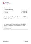
Microcontrollers
ApNote
AP2922
additional file
AP292201.EXE available
‘C’ CAN Driver Routines for the C166 Family
This application note describes CAN protocol driver software routines written in ‘C’ for
the members of the Siemens 16-bit microcontroller family C166 which are equipped
with an on-chip CAN module (e.g. C167CR, C164CI).
Authors: Axel Wolf / SCI Cupertino ICD - Dr. Jens Barrenscheen / HL MC PD 8
Semiconductor Group
05.97, Rel. 01
’C’ CAN Driver Routines
for the C166 family
1 Introduction....................................................................................................................3
1.1 Abstract.........................................................................................................................3
1.2 CAN Driver Routines Overview ....................................................................................3
1.3 Files included in the CAN Driver ApNote......................................................................4
1.4 Global Variables used by the Driver Routines..............................................................4
1.5 Notes concerning this ApNote ......................................................................................5
2 Routine #1: Initialization Procedure for the CAN Module...........................................7
3 Routine #2: Configuring a Message Object of the CAN Module..............................10
4 Routine #3: Load the data bytes of a Message Object.............................................13
5 Routine #4: Read the data bytes of a Message Object (1..14) .................................15
6 Routine #5: Read out Message Object 15 (Basic CAN Message Object) ...............17
7 Routine #6: Send a Message Object ..........................................................................20
8 Routine #7: Check a Message Object (1..14) for new data ......................................22
9 Routine #8: Check Message Object 15 for new data or new remote frame............24
10 Routine #9: Check for a Bus Off Situation in the CAN Module..............................25
11 Hints concerning the CAN Library CAN16X1.LIB....................................................26
12 Hints concerning the Example Programs................................................................26
13 Hints concerning the Interrupt Service Routine CISR16X1.C ................................30
14 Hints concerning the Header File CREG_16X.H......................................................33
15 Hints concerning the CANalyzer Configuration Files (*.CFG) ...............................33
AP2922 ApNote - Revision History
Actual Revision : Rel.01
Previous Revision: --Page of
Page of
Subjects changes since last release)
actual Rel. prev. Rel.
Semiconductor Group
2 of 33
AP2922 05.97
’C’ CAN Driver Routines
for the C166 family
1
Introduction
1.1
Abstract
This application note describes CAN protocol driver software routines for the members of
the Siemens 16-bit microcontroller family C166 which are equipped with an on-chip CAN
module (e.g. C167CR, C164CI).
Whilst every effort has been made to ensure the accuracy of information contained in this
application note, the authors cannot be held responsible for any consequences arising
from its use.
Please report comments, suggestions for improvement etc. to:
[email protected].
For further information concerning the on-chip CAN module on the C166 devices or the
C166 microcontroller itself, please refer to the document “Description of the on-chip CAN
module” and the respective derivative’s User’s Manual.
For further information concerning the CAN protocol, Siemens’ CAN devices and
additional CAN ApNotes, please refer to
− http://www.sci.siemens.com/can.html
For further information concerning Siemens’ Microcontrollers, please refer to
− http://www.sci.siemens.com/
(select the microcontrollers)
− http://www.siemens.de/Semiconductor/products/products.htm (select the MC’s)
1.2
CAN Driver Routines Overview
The following table shows an overview of the included CAN driver routines
Table 1-1:
Included driver routines
Initialization routine for the CAN module:
init_can_16x(..)
Define a message object in the CAN module:
def_mo_16x(..)
Load the data bytes of a message object:
ld_modata_16x(..)
Read the data bytes of a message object:
rd_modata_16x(..)
Read the contents of message object 15:
rd_mo15_16x(..)
Send message object
send_mo_16x(..)
Check for new data in a message object:
check_mo_16x(..)
Check for new data or remote frame in message object check_mo15_16x(..)
15:
Check if a bus off situation has occurred and recover check_busoff_16x(..)
from bus off:
Semiconductor Group
3 of 33
AP2922 05.97
’C’ CAN Driver Routines
for the C166 family
1.3
Files included in the CAN driver ApNote
Table 2 shows all the files that are part of this ApNote. You will find them in the additional
file AP292201.EXE.
Table 1-2:
Files belonging to this ApNote
Name
CAN16X1.LIB
EXS_16X1.C,
EXX_16X1.C,
EXI_16X1.C
CISR16X1.C
CREG_16X.H
EXS_16X1.CFG,
EXX_16X1.CFG
1.4
Explanation
CAN Library
CAN driver routine library to be linked to your application programs. See
also section 11.
Example programs
Gives an idea of how to use the CAN driver routines in your application.
Just standard CAN (11-bit identifier) messages are used in EXS_16X1.C,
standard and extended (29-bit) messages are used in EXX_16X1.C.
Interrupts are evaluated when using EXI_16X1.C plus CAN interrupt
service routine CISR16X1.C. See section 12 for details.
CAN Interrupt service routine
Can be used together with EXI_16X1.C to evaluate interrupts of the CAN
module. See section 13 for details.
Header File
Include file for the declaration of the Control Registers of the CAN
module. Is included in some of the source files and in the CAN interrupt
service routine (see also section 14).
CANalyzer Configuration files
If you have a Windows-based Vector/Softing CANalyzer, this
configuration file is prepared to communicate with the example programs
mentioned above.
EXS16X1.CFG works together with EXS_16X1.C and EXI_16X1.C.
EXX_16X1.CFG works together with EXX_16X1.C.
See section 15 for details.
Global Variables used by the Driver Routines
The global variables used by the CAN driver routines can be found in table 3. These
variables can not be accessed via the example programs, though.
Semiconductor Group
4 of 33
AP2922 05.97
’C’ CAN Driver Routines
for the C166 family
Table 1-3:
Global variables used by the CAN driver routines
Name
id_ptr_16x[16]
Type
unsigned int *
db0_ptr_16x[16]
unsigned char *
msg_ctrl_ptr_16x[16
]
unsigned int *
msg_conf_ptr_16x[16
]
unsigned char *
dir_bit_16x[16]
unsigned char
xtd_bit_16x[16]
unsigned char
dlc_16x[16]
unsigned char
1.5
Task
Field of 16 pointers (only [1]…[15] are used) to
the Upper Arbitration Registers of the message
objects 1..15.
Field of 16 pointers (only [1]..[15] are used) to
the data byte 0 of the message objects 1..15.
Field of 16 pointers (only [1]..[15] are used) to
the Message Control Registers of message
objects 1..15.
Field of 16 pointers (only [1]..[15] are used) to
the Message Configuration Registers of
message objects 1..15.
Field of 16 chars (only [1]..[15] are used) which
contain a copy of the direction bits of the
message objects 1..15.
Field of 16 chars (only [1]..[15] are used) which
contain a copy of the extend bits of the
message objects 1..15.
Field of 16 chars (only [1]..[15] are used) which
contain a copy of the data length code of the
message objects 1..15.
Notes concerning this ApNote
Before using the CAN driver software, please read the following notes.
•
The CAN example programs have been compiled and tested with the BSO/Tasking
compiler C166. To make compilations with other compilers easier, the routines don’t
really use BSO/Tasking specific code. Still slight changes may be necessary to
compile them with an other C166 family compiler.
•
In the additional file AP292201.EXE, you will find all the files discussed in this ApNote
(source files for the routines, example programs, interrupt service routine etc.)
•
At least in this first version of this ApNote, the 16x CAN driver routines are written in a
way that they can be easily ported to other C166 compilers or even to the 8-bit world
to be used together with the Siemens 8-bit derivatives with integrated CAN module
(e.g. C505C, C515C). The routines are furthermore designed for easy handling of the
CAN module by the user. They do not claim to be optimized for small code generation
or fast execution speed.
Semiconductor Group
5 of 33
AP2922 05.97
’C’ CAN Driver Routines
for the C166 family
•
Nevertheless, the names of the driver procedures / functions and all other files
included in this ApNote contain the letters “16X” to differentiate between the different
CAN driver ApNotes that are available (or planned) for other Siemens CAN
components:
Table 1-4:
Differentiation between files belonging to different ApNotes
Name includes… Explanation:
16X
CAN drivers for C166 family
500
CAN drivers for C500 family
92
CAN drivers for Siemens standalone CAN controller 81C92
91
CAN drivers for Siemens standalone CAN controllers 81C91/90
•
The CAN driver routines in this ApNote use two different approaches of accessing the
CAN registers. For the general CAN control registers, on-the-fly casting from near
address to pointers is used. The registers within the message objects, however, are
accessed by proper pointer types.
•
For best efficiency, execute the driver routines in segment 0 of the memory (first 64k
code segment).
•
Within the routines very often the pointers e.g. to the data bytes are copied into a local
dummy pointer so that the original pointer remains untouched during the routine (e.g.
in a loop).
•
The send_mo_16x procedure won’t work without having defined a message object
(def_mo_16x) AND having specified the data bytes with ld_mo_16x to prevent the
transmission of invalid data.
Semiconductor Group
6 of 33
AP2922 05.97
’C’ CAN Driver Routines
for the C166 family
2
Routine #1: Initialization Procedure for the CAN Module
Table 2-1:
Procedure overview
Procedure name:
init_can_16x(P1, P2, P3, P4)
Task:
initialize the global registers of the CAN module
Input parameters:
P1..P4 (see below)
Returns:
---
Name of C-source file:
INCAN16X.C
Table 2-2:
Input parameters
No
Meaning
Type
P1
baud rate
[kbit/s]
unsigned
int
P2
EIE bit
unsigned
char
P3
P4
SIE bit
IE bit
unsigned
char
unsigned
char
Possible
values
50, 125,
250, 500,
1000
0:
Effect
1:
0:
•
•
1:
0:
•
•
1:
•
Bit timing register will be loaded with the values
corresponding to the selected baud rate
•
No error interrupts are generated from the
CAN module to the C16x CPU.
Error interrupts are enabled.
No status interrupts are generated from the
CAN module to the C16x CPU.
Status interrupts are enabled.
Interrupt line from the CAN module to the
C16x CPU is disabled.
Interrupt line enabled.
Calling example:
init_can_16x(
Semiconductor Group
1000, 0, 0, 1);
CAN interrupts enabled
no status interrupts
no error interrupts
Baud rate 1 Mbit/s
7 of 33
AP2922 05.97
’C’ CAN Driver Routines
for the C166 family
Table 2-3:
Local variables
Name
Type
baud_rate
unsigned
char
unsigned
char
unsigned
char
unsigned
char
unsigned
char
unsigned
char *
eie
sie
ie
i, n
dummy_dbptr
Corresp.
Input
parameter
P1
Task
P2
holds error interrupt enable (1) / disable (0)
P3
holds status interrupt enable (1) / disable (0)
P4
holds general CAN interrupt enable (1) /
disable (0)
loop variables
-----
holds selected baud rate
is loaded with db0_ptr_16x[i] in the procedure.
Used to reset all data bytes in all message
objects.
Additional Information:
This will be the first procedure called in the main program. The procedure performs the
following actions:
•
•
•
Set port pin P4.6 (CAN TxD) to output
Set port pin P4.5 (CAN RxD) to input
Load above mentioned pointers to the different registers of the on-chip CAN module:
After the “for” loop the pointers are set as follows:
Table 2-4:
Pointer Setting in procedure init_can_16x
Pointer
msg_ctrl_ptr_16x[n]
Target
Address
EFn0H
id_ptr_16x[n]
EFn2H
msg_conf_ptr_16x[n]
EFn6H
db0_ptr_16x[n]
EFn7H
Register located there
Message Control Registers of message
object n
Upper Arbitration Register of MO n
Message Configuration Registers of
message object n
Data byte 0 of message object n
Please compare to the following figure:
Semiconductor Group
8 of 33
AP2922 05.97
’C’ CAN Driver Routines
for the C166 family
Message Control
+0
Object Start Address
+2
Arbitration
Data0
+4
Message Config.
Msg. Config.
+6
+6
+8
Data 7...0
+10
+12
Reserved
+14
Figure 2-1:
Message Object structure in the C167CR / C164CI
•
•
•
•
•
•
•
Clear the arrays dir_bit_16x[n], xtd_bit_16x[n], dlc_16x[n]
Initialize the Bit Timing Register according to the specified baud rate
Set the Global Masks in a way that for message objects 1..14 each bit of the standard /
extended identifier of the incoming frame must match to store the message into the
respective message object.
Set the Mask of Last Message in a way that all messages which cannot be stored in
message objects 1..14 are stored in message object 15 (enable Basic CAN feature).
Set all message objects to NOT VALID.
Set all data bytes in all message objects to 0.
Set the user specified values for interrupt control (bits EIE, SIE, IE) in the Control
Register (EF00H)
Semiconductor Group
9 of 33
AP2922 05.97
’C’ CAN Driver Routines
for the C166 family
3
Routine #2: Configuring a Message Object of the CAN Module
Table 3-1:
Procedure overview
Procedure name:
def_mo_16x(P1, P2, P3, P4, P5, P6, P7)
Task:
configure one message object of the CAN module
Input parameters:
P1..P7 (see below)
Returns:
---
Name of C-source file:
DEFMO16X.C
Table 3-2:
Input parameters
No
Meaning
Type
P1
# of
message
object to be
configured
eXTenD bit
unsigned
char
P2
unsigned
char
P3
Message
Identifier
(HEX-code!)
unsigned
long
P4
DIRection bit
unsigned
char
Possible
values
1..15
Effect
0:
•
1:
0H …3FFH
(std); 0H …
1FFFFFFFH
(extended)
0:
1:
P5
Specified message object (MO) will be
configured and can then be used for CAN
communication.
MO will be configured for standard CAN
(11-bit identifier).
• Extended CAN (29-bit ID) is selected.
Specified Identifier will be applied to the
message object. The message object will the
receive / transmit message which carry this
specified identifier.
• MO will be configured to receive data
frames and transmit remote frames.
• MO will be configured to transmit data
frames and receive remote frames.
Specifies length of the data field on
transmission of the MO. Set to 0 for remote
frames.
unsigned
char
0..8
P6
Data Length
Code of MO
to be
configured
TXIE bit
unsigned
char
0:
1:
•
•
P7
RXIE bit
unsigned
char
0:
1:
•
•
Semiconductor Group
10 of 33
MO will generate no transmit interrupts.
MO will generate an interrupt on each
successful transmission of a frame.
MO will generate no receive interrupts.
MO will generate an interrupt on each
successful reception of a frame.
AP2922 05.97
’C’ CAN Driver Routines
for the C166 family
Calling example:
def_mo_16x(
4, 0, 0x123, 1, 8, 0, 0
);
RXIE=0
TXIE=0
DLC=8
Transmit data frames
Identifier
Standard CAN MO (11-bit ID)
MO number
Table 3-3:
Local variables
Name
Type
nr
unsigned
char
unsigned
char
unsigned
long
unsigned
char
xtd
id
dir
dlc
Corresp.
input
parameter
P1
Task
P2
holds specified XTD bit
“1” = 29 bit ID; “0” = 11 bit ID
holds specified identifier
P3
P4
unsigned
char
unsigned
char
P5
rxie
unsigned
char
P7
dummy_int
unsigned
int
unsigned
int *
---
txie
dummy_idptr
Semiconductor Group
P6
---
holds specified message object no.
holds specified DIR bit
“1” = transmit data frames,
“0” = receive data frames
holds specified data length code
holds specified TXIE bit
“1” = transmit interrupts enabled,
“0” = transmit interrupts disabled
holds specified RXIE bit
“1” = receive interrupts enabled,
“0” = receive interrupts disabled
used to temporarily store 16 bit values
is loaded with id_ptr_16x[i]+1 in the procedure
which is the Lower Arbitration Register. Used
to load this register.
11 of 33
AP2922 05.97
’C’ CAN Driver Routines
for the C166 family
Additional Information:
Before being able to transmit or receive any frame, the message objects that are going to
be used must be configured which is done with this procedure. Only message object
numbers between 1 and 15 are accepted. The procedure has to be called for each
message object separately.
The procedure performs the following actions:
•
•
•
•
Check if the specified message object is valid (number between 1 and 15).
Load the Upper Arbitration Register and the Lower Arbitration Register with the
specified identifier value.
Load the Message Control Register:
- For transmit objects (DIR=1), CPUUPD is set. Therefore the message object can not
yet be transmitted, because its data bytes do not yet contain valid values. Load the
message object’s data bytes before transmitting (see next procedure).
- For receive objects (DIR=0), there’s no CPUUPD field but this bit field is called
MSGLST here (Message Lost). It will be reset by this procedure as no message has
been lost so far.
- Add the values specified for TXIE and RXIE to the Message Control Register.
Load the Message Configuration Register with the values specified for DLC, DIR and
XTD.
Semiconductor Group
12 of 33
AP2922 05.97
’C’ CAN Driver Routines
for the C166 family
4
Routine #3: Load the data bytes of a Message Object
Table 4-1:
Procedure overview
Procedure name:
ld_modata_16x(P1, P2)
Task:
load the data bytes of one message object of the CAN module
Input parameters:
P1, P2 (see below)
Returns:
---
Name of C-source file:
LDMOD16X.C
Table 4-2:
Input parameters
No
Meaning
Type
P1
# of
message
object
address of
an upload
data array[8]
unsigned
char
P2
address
Possible
values
1..14
Effect
user
specific 8byte buffer
The data bytes of the specified MO will be filled
with the contents of the 8-byte array whose start
address (1st element) is passed on to this
procedure.
Data bytes of specified MO will be loaded.
Calling example:
ld_modata_16x(
Semiconductor Group
4, upload_data_buf );
address of first element of 8-byte
array previously filled with the
data to be sent out (&upload_data_buf[0])
MO number
13 of 33
AP2922 05.97
’C’ CAN Driver Routines
for the C166 family
Table 4-3:
Local variables
Name
Type
nr
unsigned
char
unsigned
char *
upl_data_ptr
Corresp.
Input
parameter
P1
Task
P2
is loaded with the address of the first element
of the 8-byte array filled with the data to be
sent.
is loaded with db0_ptr_16x[nr] in the
procedure. This is where the data will be
copied.
loop variable
dummy_dbptr
unsigned
char *
---
i
uns. char
---
holds specified message object
Additional Information:
Before being able to transmit any data frame, the message object’s data bytes have to be
loaded at least once which can be done with this procedure. Please note that as MO 15
cannot be transmitted, its data bytes cannot be loaded with this procedure.
Only message object numbers between 1 and 14 are accepted. The procedure has to be
called for each message object separately.
The procedure performs the following actions:
•
•
•
•
Check if the specified message object is valid (number between 1 and 14).
Set CPUUPD and NEWDAT in the Message Control Register of the specified
message object to indicate that the CPU is actually working on the message object’s
data.
Copy data bytes from the upload buffer specified in input parameter P2 to the data
bytes of the message object specified in input parameter P1.
Reset CPUUPD in the Message Control Register to enable transmission of the
message object.
Semiconductor Group
14 of 33
AP2922 05.97
’C’ CAN Driver Routines
for the C166 family
5
Routine #4: Read the data bytes of a Message Object (1..14)
Table 5-1:
Procedure overview
Procedure name:
rd_modata_16x(P1, P2)
Task:
read the data bytes of one message object of the CAN module
Input parameters:
P1, P2 (see below)
Returns:
---
Name of C-source file:
RDMOD16X.C
Table 5-2:
Input parameters
No
Meaning
Type
P1
# of
message
object
address of a
download
data array[8]
unsigned
char
P2
address
Possible
values
1..14
Effect
user
specific 8byte buffer
The 8-byte array whose start address (1st
element) is passed on to this procedure is filled
with the data bytes of the specified MO.
Data bytes of specified MO will be read.
Calling example:
rd_modata_16x(
Semiconductor Group
4, download_data_buf );
address of first element of 8-byte
array which shall be filled with the
data bytes of the spec. message object
MO number
15 of 33
AP2922 05.97
’C’ CAN Driver Routines
for the C166 family
Table 5-3:
Local variables
Name
Type
nr
unsigned
char
unsigned
char *
downl_data_ptr
dummy_dbptr
i
dummy_char
unsigned
char *
uns. char
uns. char
Corresp.
input
parameter
P1
Task
P2
is loaded with the address of the first element
of the 8-byte array to be filled with the data
bytes of the specified MO
is loaded with db0_ptr_16x[nr] in the procedure.
This is where the data will be copied from.
loop variable
used to temporarily store 8 bit values
-------
holds specified message object
Additional Information:
This procedure is used to read the data bytes of a certain message object and copy them
into a user specific 8-byte data buffer. Usually it will be called after the software has
detected that new data has been written into a message object using the function
check_mo_16x (see below). Please note that for MO 15 a separate procedure to read out
this message object is available (see below).
Only message object numbers between 1 and 14 are accepted. The procedure has to be
called for each message object separately.
The procedure performs the following actions:
•
•
•
•
Check if the specified message object is valid (number between 1 and 14).
Store the actual data length code of the new message into the global variable
dlc_167[nr]
Clear INTPND and NEWDAT in the Message Control Register of the specified
message object in order to allow a new message to be written into this message object
during this procedure is running
Copy the data bytes (their number is specified by the actual dlc) from the message
object specified in input parameter P1 to the download buffer specified in input
parameter P2.
At the end, the procedure is only left if NEWDAT has not been updated to 1, i.e. no new
message has arrived for this message object during the execution of this procedure. If
NEWDAT has been set to 1 again, the procedure is repeated. In this way, only the latest
data bytes are returned.
Semiconductor Group
16 of 33
AP2922 05.97
’C’ CAN Driver Routines
for the C166 family
6
Routine #5: Read out Message Object 15 (Basic CAN Message Object)
Table 6-1:
Procedure overview
Procedure name:
rd_mo15_16x(P1, P2, P3)
Task:
read message object 15 of the CAN module
Input parameters:
P1..P3 (see below)
Returns:
---
Name of C-source file:
RDM1516X.C
Table 6-2:
Input parameters
No
Meaning
Type
Possible
values
user
specific 8byte buffer
P1
address of a
download
data array[8]
address
P2
address of a
download
identifier
variable
address
user
specific
long
variable
P3
address of a
download
data length
code
variable
address
user
specific
byte
variable
Effect
The 8-byte array whose start address (1st
element) is passed on to this procedure is filled
with the data bytes of the MO 15 buffer which is
momentarily accessed by the CPU.
The long variable whose address is passed on to
this procedure is filled with the hexadecimal
value of the identifier stored in the Upper and
Lower Arbitration Register of the MO 15 buffer
which is momentarily accessed by the CPU.
The char variable whose address is passed on to
this procedure is filled with the data length code
of the MO 15 Message Configuration Register
buffer which is momentarily accessed by the
CPU.
Calling example:
rd_mo15_16x(mo15_data_buf1, &mo15_id1,
&mo15_dlc1);
address of MO 15
data length code variable
address of MO15 identifier variable
address of first element of 8-byte array which shall be filled with
the data bytes of MO 15 (&mo15_data_buf1[0])
Semiconductor Group
17 of 33
AP2922 05.97
’C’ CAN Driver Routines
for the C166 family
Table 6-3:
Local variables
Name
Type
mo15_db_ptr
unsigned
char *
mo15_id_ptr
unsigned
long *
P2
mo15_dlc_ptr
unsigned
char *
unsigned
char *
P3
uns. char
---
dummy_dbptr
i
Corresp.
input
parameter
P1
---
Task
is loaded with the address of the first element
of the 8-byte array to be filled with the data
bytes of the specified MO
is loaded with the address of the long variable
to be filled with the hexadecimal value of MO
15
is loaded with the address of the char variable
to be filled with the data length code of MO 15
is loaded with db0_ptr_16x[15] in the
procedure. This is where the data will be
copied from.
loop variable
Additional Information:
This procedure is used to read the data bytes, the data length code and the identifier of
message object 15 and copy them into a user specific 8-byte data buffer, a user specific
char-variable and a user specific long variable.
Usually it will be called after the software has detected that new data has been written into
message object 15 using the function check_mo_16x (see below).
Whenever using message object 15, please have in mind that message object 15 is
double buffered. This is why the input variables for this procedures have the index “1”.
The main program could have the same variables with index “2” as well (as shown in the
example program for these driver procedures).
For example, if the software has detected that a new data frame has been stored into the
message object 15 (using the procedure check_mo_16x), the software could then call the
rd_mo15_16x-procedure with the variable set indexed “1”. Before returning, this
procedure will release the momentarily accessed buffer. The software could then
immediately check message object 15 again for new data which is probably located in the
other buffer. If new data is detected here as well, the software could read out this data
again by using rd_mo15_16x, but now with the variable set indexed “2” and now
automatically accessing the other buffer.
Semiconductor Group
18 of 33
AP2922 05.97
’C’ CAN Driver Routines
for the C166 family
The procedure performs the following actions:
•
•
•
•
The data length code of the new message is read from the momentarily accessed
buffer and is stored into the user specific MO15 dlc variable and into the global
variable dlc_167[15]. Please have in mind that the dlc may be 0 if you have configured
the MO 15 to receive remote frames.
The identifier of the new message is read from the momentarily accessed buffer, is
converted into hexadecimal format and is stored in the user specific MO15 identifier
variable.
The data bytes of the new message (their number is specified by the actual dlc) are
read from the momentarily accessed buffer and are stored in the user specific MO15
data byte buffer. Please have in mind that the data has to be ignored if you have
configured MO 15 to receive remote frames.
Clear INTPND, RMTPND and NEWDAT in the Message Control Register of MO 15 in
order to release the momentarily accessed buffer of MO 15
Semiconductor Group
19 of 33
AP2922 05.97
’C’ CAN Driver Routines
for the C166 family
7
Routine #6: Send a Message Object
Table 7-1:
Procedure overview
Procedure name:
send_mo_16x(P1)
Task:
request transmission of one message object of the CAN module
Input parameters:
P1 (see below)
Returns:
---
Name of C-source file:
SNDMO16X.C
Table 7-2:
Input parameters
No
Meaning
Type
P1
# of
message
object
unsigned
char
Possible
values
1..14
Effect
Specified MO will be transmitted.
Calling example:
send_mo_16x( 4
);
MO number
Table 7-3:
Local variables
Name
Type
nr
unsigned
char
Semiconductor Group
Corresp.
Input
parameter
P1
Task
holds specified message object
20 of 33
AP2922 05.97
’C’ CAN Driver Routines
for the C166 family
Additional Information:
This procedure transmits the specified message object. If the message object was
configured with DIR=1, then a data frame will be transmitted. If the message object was
configured with DIR=0, then a remote frame will be transmitted. Please note that as MO
15 cannot be transmitted, this procedure cannot be applied to MO 15.
Please note that before being able to transmit any data frame, the message object’s data
bytes have to be loaded at least once which can be done with the procedure
ld_modata_16x.
Only message object numbers between 1 and 14 are accepted. The procedure has to be
called for each message object separately.
The procedure performs the following actions:
•
•
Check if the specified message object is valid (number between 1 and 14).
Set TXRQ in the Message Control Register of the specified message object to request
the transmission of this message object.
Semiconductor Group
21 of 33
AP2922 05.97
’C’ CAN Driver Routines
for the C166 family
8
Routine #7: Check a Message Object (1..14) for new data
Table 8-1:
Function overview
Function name:
check_mo_16x(P1)
Task:
check if new data has been received in one message object of
the CAN module
P1 (see below)
Input parameters:
Returns:
Name of C-source file:
“1” if new the specified message object contains new data, “0”
otherwise.
CHKMO16X.C
Table 8-2:
Input parameters
No
Meaning
Type
P1
# of
message
object
unsigned
char
Possible
values
1..14
Effect
Specified MO will be checked for new data.
Calling example:
if (check_mo_16x( 4 )) {..};
MO number
Table 8-3:
Local variables
Name
Type
nr
unsigned
char
unsigned
char
new_data_var
Semiconductor Group
Corresp.
Input
parameter
P1
Task
---
holds value to be returned to main program
holds specified message object
22 of 33
AP2922 05.97
’C’ CAN Driver Routines
for the C166 family
Additional Information:
This function checks if new data has been written into the data bytes of the specified
message object. It will be applied to message objects that were configured with DIR=0 i.e.
that they are able to receive data frames. Please note that for MO 15 a separate function
called check_mo15_16x is available.
If the result of this function is true, most likely the procedure rd_modata_16x will be called
to read out the new data (as shown in the example program).
Only message object numbers between 1 and 14 are accepted. The function has to be
called for each message object separately.
This function performs the following actions:
•
•
•
Check if the specified message object is valid (number between 1 and 14).
Check NEWDAT in the Message Control Register of the specified message object.
Return “1” if NEWDAT is set, otherwise return “0”.
Semiconductor Group
23 of 33
AP2922 05.97
’C’ CAN Driver Routines
for the C166 family
9
Routine #8: Check Message Object 15 for new data or new remote frame
Table 9-1:
Function overview
Function name:
check_mo15_16x()
Task:
check if new data or a new remote frame has been received in
message object 15 of the CAN module
---
Input parameters:
Returns:
Name of C-source file:
“1” if new the specified message object contains new data, “0”
otherwise.
CHM1516X.C
Input parameters:
none
Calling example:
if (check_mo15_16x()) {..};
Table 9-2:
Local variables
Name
Type
new_event_var
unsigned
char
Corresp.
Input
parameter
---
Task
holds value to be returned to main program
Additional Information:
This function checks if new data has been written into the data bytes of MO 15 (if this
message object has been configured to receive data frames (DIR=0) or if a new remote
frame has been received in MO 15 (if this message object has been configured to receive
remote frames (DIR=1).
If the result of this function is true, most likely the procedure rd_mo15_16x will be called to
read out MO 15 (as shown in the example program).
This function performs the following actions:
•
•
Check NEWDAT and RMTPND in the Message Control Register of MO 15.
Return “1” if one of these bits is set, otherwise return “0”.
Semiconductor Group
24 of 33
AP2922 05.97
’C’ CAN Driver Routines
for the C166 family
10
Routine #9: Check for a Bus Off Situation in the CAN Module
Table 10-1:
Function overview
Function name:
check_busoff_16x()
Task:
check if a bus off situation has occurred in the CAN module
Input parameters:
---
Returns:
“1” if CAN controller was in bus off state, “0” otherwise.
Name of C-source file:
CHKBO16X.C
Input parameters:
none
Calling example:
if (check_busoff_16x()) {..};
Table 9-2:
Local variables
Name
Type
busoff_var
unsigned
char
Corresp.
Input
parameter
---
Task
holds value to be returned to main program
Additional Information:
This function checks if a bus off situation has occurred in the CAN module.
This function performs the following actions:
•
•
•
Check if the BOFF bit in the Status Register has been set to 1 by the CAN controller.
If BOFF is set, this indicates a bus off situation. To recover from the bus off, the
function resets the INIT bit in the Control Register.
Return “1” if BOFF was set, otherwise return “0”.
Semiconductor Group
25 of 33
AP2922 05.97
’C’ CAN Driver Routines
for the C166 family
11
Hints concerning the CAN Library CAN16X1.LIB
The file CAN16X1.LIB contains all CAN driver routines described in this application note.
It was created with the BSO/Tasking archive utility “ar166”. A new class called
“CAN16X1LIB” has been created for the library to be able to locate the CAN driver
routines separately.
To use the CAN driver routines, just link this library to your application programs. At the
beginning of your application programs, you should declare the routines you want to use
as “external” as shown in the example programs.
The source files of the CAN driver routines are also included in this application note. Feel
free to alter the source files and generate your own customized CAN library.
12
Hints concerning the Example Programs
12.1
Overview
There are three example programs included in this application note. The following table
shows the differences between the files.
Table 12-1:
Differences between the example programs
File
11-bit identifier
used:
29 bit identifier
used:
CAN module
interrupts used:
EXS_16X1.C
yes
no
no
EXX_16X1.C
yes
yes
no
EXI_16X1.C
yes
no
yes
Please note that EXI_16X1.C depends on the additional use of the interrupt service
routine CISR16X1.C.
The CAN example programs have been compiled and tested with the BSO/Tasking
compiler C166. Slight changes may be necessary to compile them with an other compiler
for the C166 family.
The example programs are all following the same structure. The parts that are important
for the use of the CAN driver routines are now discussed. Please note that the target of
the example programs is not to execute an ingenious program but to show how to work
with the CAN driver routines.
12.2
#define statements
The example programs use some constants for a better overview. The following table
describes the most important constants.
Semiconductor Group
26 of 33
AP2922 05.97
’C’ CAN Driver Routines
for the C166 family
Table 12-2:
Constants used in the example programs
Defined constant
Meaning in the example program
MY_IEN_BIT
Used to generally enable (=1) or disable (=0) interrupt to the CPU
via the bit IEN in the PSW register.
MY_XP0IC_VALUE
Used to enable the interrupt from the CAN module (CPU side) and
set it to a certain interrupt priority level. This constant will be used to
load the XP0IC register. If XP0IC contains 0, the CAN module
interrupt is disabled.
MY_BAUD_RATE
Used to specify the input parameter P1 of procedure “init_can_16x”.
EIE_BIT
Used to specify the input parameter P2 of procedure “init_can_16x”.
SIE_BIT
Used to specify the input parameter P3 of procedure “init_can_16x”.
IE_BIT
Used to specify the input parameter P4 of procedure “init_can_16x”.
MOx_XTD_BIT
Used to specify the input parameter P2 of procedure “def_mo_16x”.
M0x_ID
Used to specify the input parameter P3 of procedure “def_mo_16x”.
MOx_DIR_BIT
Used to specify the input parameter P4 of procedure “def_mo_16x”.
MOx_DLC
Used to specify the input parameter P5 of procedure “def_mo_16x”.
MOx_TXIE_BIT
Used to specify the input parameter P6 of procedure “def_mo_16x”.
MOx_RXIE_BIT
Used to specify the input parameter P7 of procedure “def_mo_16x”.
12.3
Prototypes for the CAN driver routines
After the #define statements, the CAN driver routines are declared as “external” in the
example programs. This avoids warnings created by your compiler when compiling your
application program.
12.4
Local variables of the example programs
The example programs use different local variables described in the following table.
Semiconductor Group
27 of 33
AP2922 05.97
’C’ CAN Driver Routines
for the C166 family
Table 12-3:
Local variables of the example programs
Name
i
upload_data_buf[8]
download_data_buf[8]
mo15_db_buf1[8]
mo15_db_buf2[8]
mo15_id1
mo15_id2
mo15_dlc1
mo15_dlc2
Type
unsigned
char
unsigned
char
Used by
all example
programs
all example
programs
unsigned
char
unsigned
char
unsigned
char
EXS_16X1,
EXX_16X1
EXS_16X1,
EXX_16X1
EXS_16X1,
EXX_16X1
unsigned
long
unsigned
long
unsigned
char
unsigned
char
EXS_16X1,
EXX_16X1
EXS_16X1,
EXX_16X1
EXS_16X1,
EXX_16X1
EXS_16X1,
EXX_16X1
Task
loop variable
contains dummy data to load
the data bytes of message
object 1
used to store data received in
message object 2
used to store data bytes from
first buffer of MO15
could be used to store data
bytes from second buffer of
MO15
used to store identifier from first
buffer of MO15
could be used to store identifier
from second buffer of MO15
used to store data length code
from first buffer of MO15
could be used to store data
length code from second buffer
of MO15
The variables mo15_db_buf2[8], mo15_id2 and mo15_dlc2 are currently not used by the
example programs. Nevertheless they are defined to show the double buffering of
message object 15. See also section 9.
12.5
Preparations for the main loop
The general preparations for the main loop are the same in all three example programs.
First, the CAN module is initialized by calling the routine “can_init_16x”. Then message
objects 1, 2, 3, and 15 are configured using the routine “def_mo_16x”. After that, the
register XP0IC is loaded and the Bit IEN is set.
12.6
The main loop
Semiconductor Group
28 of 33
AP2922 05.97
’C’ CAN Driver Routines
for the C166 family
The main loop is divided into 4 sections. Between the sections a delay of 10 ms will be
generated by calling the local routine “delay” which generates time delays between 1 ms
and 26 ms using timer T4 of the microcontroller. All example programs execute section 1.
In example program EXI_16X1.C, however, the sections 2, 3 and 4 are no longer in the
example program itself but are all handled interrupt controlled by the interrupt service
routine CISR16X.C. See section 13 for details.
In section 1, the data bytes of message object 1 (which has been configured as a
message object to transmit standard data frames with identifier “001H”) are loaded with the
data stored in the upload data buffer by using the procedure “ld_modata_16x”. After that,
message object 1 is transmitted by calling “send_mo_16x”. Finally, to have different data
bytes each time message object 1 is sent, each byte of the upload data buffer is
incremented by 1. Therefore, section 1 initiates the transfer of a standard data frame with
the identifier “001H” and 8 different data bytes roughly every 40 ms.
In section 2, message object 2 (which has been configured for the reception of standard
data frames with the identifier “002H”) is checked for new data frames by calling
“check_mo_16x”. If new data has been written into message object 2, the function will
return “1” and the software will then read the new data bytes into the download data
buffer. After that, message object 3 (which has been configured as a message object to
transmit standard data frames with identifier “003H”) is loaded with the data bytes just read
from message object 2 and is transmitted. Therefore, section 2 initiates the transfer of a
standard data frame with the identifier “003H” and the data bytes received in message
object 2 each time new data is detected in message object 2.
In section 3, the basic CAN feature of the CAN module is used. Message object 15 (which
has been configured for the reception of standard data frames (EXS_16X1.C) / extended
data frames (EXX_16X1.C) with any identifier) is checked for new data frames by calling
“check_mo15_16x”. If new data has been written into message object 15, the function will
return “1” and the software will then read the new data bytes into the message object 15
data buffer 1. Additionally, the identifier and the data length code of the data frame that
had been written into message object 15 will be read and stored into the respective
variables “mo15_id1” and “mo15_dlc1”. After that, message object 14 is configured as a
message object to transmit data frames with the same identifier as the frame from
message object 15 and the same data length code as well. Message object 14 is then
loaded with the data bytes just read from message object 15 and is transmitted.
Therefore, section 3 initiates the return of exactly the same data frame by message object
14 as was just read from message object 15. In a similar way, remote frames received by
message object 15 (if message object 15 is configured for the reception of remote frames)
could be read, the identifier could be evaluated by the CPU and the corresponding data
frame could be sent in return (if necessary).
Semiconductor Group
29 of 33
AP2922 05.97
’C’ CAN Driver Routines
for the C166 family
Section 4 calls “check_busoff_16x” to check whether the CAN module has entered the
bus off state or not. If so, the bus off recovery is initiated in “check_busoff_16x” itself (bit
INIT in the CAN module’s control register is cleared). Additionally, the main program could
execute some application specific code.
13
Hints concerning the Interrupt Service Routine CISR16X1.C
13.1
Overview
CISR16X1.C is an example for a CAN interrupt service routine. Using the interrupts of the
CAN module will increase the performance of your application because the CPU load is
significantly reduced. Furthermore, your application will be able to react on CAN bus
traffic much faster than it would be able to without using the CAN module interrupt. Please
note that the use of this interrupt service routine depends on the use of the example
program EXI_16X1.C. In other words: To be able to use the interrupt service routine, the
following conditions must be fulfilled:
•
The global interrupt enable bit IEN in register PSW of the microcontroller must be set
to “1” in the main program.
•
The CAN interrupt (CPU side) must be enabled by loading the XP0IC (X-Peripheral 0
Interrupt Control register) with an appropriate value (e.g. 0x44H for priority level 1).
•
CAN interrupts (CAN controller side) must be enabled by setting the Interrupt Enable
bit IE in the Control Register of the CAN module to “1” when initializing the CAN
module using “init_can_16x”. Also select if you want to select Status Change Interrupts
(set SIE to “1”) and / or Error Interrupts (set EIE to “1”).
•
For the enabling of message object specific interrupts, the respective bit fields TXIE
(for transmit interrupts) and/or RXIE (for receive interrupts) must be enabled in the
Message Control Register of the respective message when configuring a message
using “def_mo_16x”.
•
The interrupt service routine has to be linked to the main program, having access to
the CAN library CAN16X1.LIB.
The CAN interrupt service routine has been compiled and tested with the BSO/Tasking
compiler C166. Slight changes may be necessary to compile it with an other compiler for
the C166 family.
The contents of the CAN interrupt service routine is now discussed. Again, please note
that the target of this example interrupt service routine is to show a general example how
to work with the CAN driver routines using the CAN module interrupt.
Semiconductor Group
30 of 33
AP2922 05.97
’C’ CAN Driver Routines
for the C166 family
13.2
Contents of the CAN interrupt service routine
The routine starts with two #include statements to include the register definitions of the
used microcontroller and additionally to include the register declarations for the general
CAN control registers. After that, the CAN driver routines are declared as “external” in the
example programs. This avoids warnings created by your compiler when compiling the
interrupt service routine.
The interrupt service routine uses the following local variables:
Table 13-1:
Local variables of the example interrupt service routine
Name
status
intid
buf_no
download_data_buf[8]
mo15_db_buf[2][8]
mo15_id[2]
mo15_dlc[2]
Type
unsigned
char
unsigned
char
unsigned
char
unsigned
char
unsigned
char
unsigned
long
unsigned
char
Task
contains contents of Status Register of the
CAN module (EF01H)
contains contents of Interrupt Register of the
CAN module
contains actual number of message object
15 buffer
used to store data received in message
object 2
used to store data bytes from the two buffers
of MO15
used to store identifiers from the two buffers
of MO15
used to store data length code from the two
buffers of MO15
The whole interrupt service routine is made of a while loop. The contents of the interrupt
register is copied into the variable “intid” and the while loop is executed until the Interrupt
Register is “0”, which means all pending CAN interrupts have been correctly serviced.
Within the while loop, the CAN module Status Register is copied into the variable “status”
and is cleared afterwards. Please note: Reading the Status Register already clears a
pending Status interrupt and the Interrupt Register is updated.
The rest of the interrupt service routine is a switch statement. Depending on which
interrupt is pending (Status Change Interrupt, Error Interrupt, Message Object Interrupt),
the respective actions can be performed. In all these sections you may insert application
specific code.
Semiconductor Group
31 of 33
AP2922 05.97
’C’ CAN Driver Routines
for the C166 family
The section “Error Interrupts” will be entered e.g. if the bus off bit has been set by the
CAN module. You will also find the recovery from bus off state there which was performed
in section 4 of “main” of the two example programs not using the interrupt service routine.
The section “Message 15 receive interrupt” will be entered if new data has been written
into message object 15, used as Basic CAN receive register (earlier described as “section
3” of “main” of the two example programs not using the interrupt service routine).
If the identifier of the new data frame matches the test identifier, the software will then
read the data bytes and write them into “mo15_ db_buf[0]”. Additionally, the identifier and
the data length code of the data frame that had been written into message object 15 will
be read and stored into the respective variables “mo15_id[0]” and “mo15_dlc1[0]”. This
will also release the momentarily accessed MO15 buffer. After that, message object 14 is
configured as a message object to transmit data frames with the same identifier as the
frame from message object 15 and the same data length code as well. Message object 14
is then loaded with the data bytes just read from message object 15 and is transmitted.
Therefore, this section initiates the return of exactly the same data frame by message
object 14 as was just read from message object 15. In a similar way, remote frames
received by message object 15 (if message object 15 is configured for the reception of
remote frames) could be read, the identifier could be evaluated by the CPU and the
corresponding data frame could be sent in return (if necessary).
Should both buffers of message object 15 have been allocated (containing new data), the
interrupt service routine will not yet be left because the Interrupt Register is still 0x01H.
The “message object 15 interrupt” section will be entered again, now accessing the other
buffer of message object 15. Therefore, the data, id and dlc from this buffer is written into
“mo15_ db_buf[1]”, “mo15_id[1]” and “mo15_dlc1[1]”. Now also the second buffer of
message object 15 is released and the interrupt service routine may be left (if no other
interrupt is pending and no new data has been written again into the other buffer of
message object 15).
Note: The Interrupt service routine will not be left until both buffers of message object 15
are released. Avoid the storage of too many messages coming close to each other into
the Basic CAN message object 15 or giving the CAN interrupt service routine a priority
which is too low to ensure proper functionality.
The section “Message 2 interrupt” will be entered if new data has been written into
message object 2 (earlier described as “section 2” of “main” of the two example programs
not using the interrupt service routine). The software will read the new data bytes into the
download data buffer. After that, message object 3 (which has been configured as a
message object to transmit standard data frames with identifier “003H”) is loaded with the
data bytes just read from message object 2 and is transmitted. Therefore, this section
initiates the transfer of a standard data frame with the identifier “003H” and the data bytes
received in message object 2 each time new data is detected in message object 2.
The interrupt service routine contains templates for the handling of other message
objects. Use these templates if you configure other message objects to generate receive
or transmit interrupts.
Semiconductor Group
32 of 33
AP2922 05.97
’C’ CAN Driver Routines
for the C166 family
14
Hints concerning the Header File CREG_16X.H
Via the #define statements in this header file, the global CAN control registers can be
accessed by using the register names which represent the contents of a pointer pointing
to the address of the respective register.
This header file is included into some of the CAN driver routine source files as well as into
the CAN interrupt service routine example CISR16X1.C.
15
Hints concerning the CANalyzer Configuration Files (*.CFG)
EXS_16X1.CFG and EXX_16X1.CFG are two configuration files designed for the
Vector/Softing CANalyzer for Windows to act as an opposite CAN node to the one that
works with the example program of the same name. You the have a small CAN network
made of the CANalyzer and “your node”.
Start the CANalyzer program and load the configuration file. Start the measurement and
then start your node by running the example program.
The CANalyzer now receives the data frames transmitted by message object 1 (identifier
001) of your node. As an “answer”, the CANalyzer sends back a data frame with identifier
002 which will be received in message object 2 in your node. The data will be copied into
message object 3 and sent out in a data frame with identifier 003 which will again be
received by the CANalyzer.
If you press the “a” key on your CANalyzer once, a data frame which matches with the test
identifier for message object 15 in your node will be sent. Therefore, your node returns
this message. Press “a” a second time and another message with the same identifier will
be sent (different dlc and data) and returned. The third time you press “a”, a data frame
which does not match with the test identifier for message object 15 will be sent. You will
see that your node performs a correct software acceptance filtering and will not return this
message. Pressing “a” for the 4th time will start this message series over again.
Note: The CANalyzer configuration files were created with the software version that works
together with the PCMCIA CANalyzer card. Problems might occur using the files with
other software designed to work with other hardware.
Semiconductor Group
33 of 33
AP2922 05.97