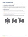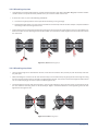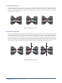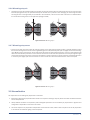
1
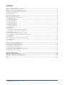
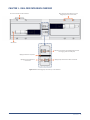
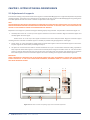
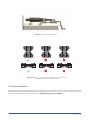
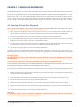
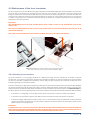
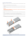
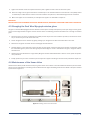
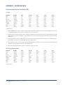
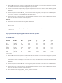
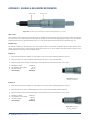
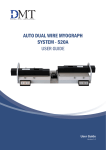
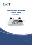
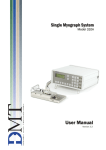
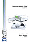
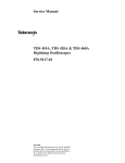
DUAL WIRE MYOGRAPH SYSTEM - 420A USER GUIDE User Guide Version 1.0 1 CONTENTS Chapter 1 - Dual Wire Myograph overview.......................................................................................................................................3 Chapter 2 - Setting up the Dual Wire Myograph..............................................................................................................................4 2.1 Adjustment of supports......................................................................................................................................................................4 2.2 Force calibration.................................................................................................................................................................................5 Chapter 3 - Experimental set-up .......................................................................................................................................................6 3.1 Mounting protocol for small arteries.................................................................................................................................................6 3.1.1 Mounting step one.......................................................................................................................................................................6 3.1.2 Mounting step two.......................................................................................................................................................................7 3.1.3 Mounting step three....................................................................................................................................................................7 3.1.4 Mounting step four.......................................................................................................................................................................8 3.1.5 Mounting step five........................................................................................................................................................................8 3.1.6 Mounting step six.........................................................................................................................................................................9 3.1.7 Mounting step seven...................................................................................................................................................................9 3.2 Normalization.....................................................................................................................................................................................9 3.3 Standard start................................................................................................................................................................................. 10 3.3.1 Principles of the standard start procedure............................................................................................................................. 10 3.2.1 Principles of the normalization procedure.............................................................................................................................. 10 3.4 Endothelium function...................................................................................................................................................................... 11 3.4.1 Principles of checking endothelium function.......................................................................................................................... 11 3.5 In vitro experiment 1: Noradrenaline contractile response.......................................................................................................... 12 3.5.1 Background............................................................................................................................................................................... 12 3.5.2 Protocol...................................................................................................................................................................................... 12 3.6 In vitro experiment 2: Acetylcholine relaxation curve................................................................................................................... 13 3.6.1 Background............................................................................................................................................................................... 13 3.6.2 Protocol...................................................................................................................................................................................... 13 Chapter 4 - Cleaning and Maintenance......................................................................................................................................... 14 4.1 Cleaning the Dual Wire Myograph.................................................................................................................................................. 14 4.2 Maintenance of the force transducer............................................................................................................................................ 15 4.2.1 Checking force transducer....................................................................................................................................................... 15 4.2.2 Force transducer replacement................................................................................................................................................. 16 4.3 Changing the Dual Wire Myograph window glass ........................................................................................................................ 17 4.4 Maintenance of the linear slides.................................................................................................................................................... 17 Appendix 1 - Buffer recipes............................................................................................................................................................ 18 Appendix 2 - Normalization theory................................................................................................................................................. 20 Appendix 3 - Reading a millimetre Micrometer............................................................................................................................ 22 Notes................................................................................................................................................................................................. 23 2 WIRE MYOGRAPH SYSTEM - 420A - USER GUIDE CHAPTER 1 - DUAL WIRE MYOGRAPH OVERVIEW Allen screws for fine alignment of the Myograph jaws (4 on each side) Port for connection to Wire Interface Micrometer Window at the bottom of the Myograph chamber for imaging (under the wire jaws) Myograph chamber separator Myograph jaw connected to micrometer Myograph jaw connected to force transducer Figure 1.1 Dual Wire Myograph with close-up of the chamber CHAPTER 1 3 CHAPTER 2 - SETTING UP THE DUAL WIRE MYOGRAPH 2.1 Adjustment of supports A successful mounting of any kind of tubular tissue segment in the Dual Wire Myograph is to a high extent dependent on perfectly matching supports. The supports are matched prior to the shipment but daily use of the Dual Wire Myograph and greasing of the transducer pinhole will over time create a need for an adjustment of the supports. NOTE THE TRANSDUCERS ARE FRAGILE AND SENSITIVE TO MECHANICAL STRAIN. BE VERY CAUTIOUS NOT TO PUT STRAIN ON THE TRANSDUCER WHEN CHANGING OR ADJUSTING THE MOUNTING SUPPORTS. IN ADDITION, VERY LITTLE FORCE SHOULD BE APPLIED TO THE SCREWS IN ORDER TO AVOID BREAKING THE THREADS. Adjustment of the supports is performed using the following step-by-step procedure. The procedure is illustrated in figure 2.1. 1. C arefully loosen screw “D” on the top of the support connected to the force transducer. Align the horizontal support and carefully tighten the screw again. Loosen screw “E” on the top of the support connected to the linear slide/micrometer. Align the horizontal support matching the force transducer connected support as carefully as possible and gently tighten the screw again. 2. L oosen screw “C” on the linear slide to roughly match the linear slide support to the force transducer support in the horizontal plane. Tighten the screw before proceeding with step 4. 3. T he plate “B” on which the linear slide is mounted is balanced on top of a small stainless steel ball making it possible to finely adjust the linear slide support in all vertical and horizontal planes using the four Allen screws “A”. Use the four Allen screws to make the final horizontal (see arrow in figure 2.1) and vertical (see arrow in figure 2.2) adjustments to match the linear slide support to the force transducer support. The correct matching of the supports is illustrated in figure 2.3. IMPORTANT AVOID CONTINUOUSLY TIGHTENING THE ALLEN SCREWS DURING THE FINAL ADJUSTMENTS: LOOSEN THE ALLEN SCREW PLACED DIAGONALLY TO THE ALLEN SCREW BEING TIGHTENED, OTHERWISE THERE IS A HIGH RISK OF DAMAGING THE DUAL WIRE MYOGRAPH FRAME. A A A A B D E C Figure 2.1 Illustration of screws for adjusting supports and horizontal adjustment 4 WIRE MYOGRAPH SYSTEM - 420A - USER GUIDE Figure 2.2 Illustration of vertical adjustment Figure 2.3 Illustration of correctly aligned supports for small vessels (left) and incorrectly aligned supports (middle and right) 2.2 Force calibration DMT recommends that the Dual Wire Myograph is force calibrated at least once every month. DMT also recommends that the Dual Wire Myograph is force calibrated every time the system has been moved or has not been used for a long period of time. See the force calibration procedure in chapter 3.7.1 in Wire Myograph Systems - User Manual. CHAPTER 2 5 CHAPTER 3 - EXPERIMENTAL SET-UP This chapter contains experimental set-up for the Dual Wire Myograph. For dissection of a vessel, please see Procedures for investigations of small vessels using a small vessel Myograph by M.J. Mulvany. 3.1 Mounting protocol for small arteries The procedure involves attaching the mounting wires to jaws which are in turn mounted on the force transducer. This force transducer is capable of measuring with a sensitivity of about 0.01 mN (1 mg), but can be damaged if the applied force exceeds about 1 N (100 g). Therefore care must be taken to avoid pressing the jaws too hard together. A movement of ~20 µm after they have touched is sufficient to hold the wires clamped. 3.1.1 Mounting step one • Cut lengths of 40 μm wire ~2.2 cm long. Mount one wire on left-hand jaw of the Dual Wire Myograph as follows. • Holding wire at far end, place centre of wire between jaws and screw jaws together so that the wire is clamped (figure 3.1 A). NOTE DO NOT CLOSE THE JAWS TOO HARD AGAINST EACH OTHER. • Bend the far end of the wire towards the left, and wrap it around under fixing screw, so the wire is wound clockwise: tightening the screw will then tighten the wire. This procedure should result in the wire being clamped between the jaws and with near end of wire pointing towards operator (figure 3.1 B-C). • Fill the Dual Wire Myograph chamber with PSS (at room temperature). See appendix 1 for example of buffer recipes. A B Figure 3.1 A, B and C Mounting step 1 6 WIRE MYOGRAPH SYSTEM - 420A - USER GUIDE C 3.1.2 Mounting step two • Using forceps to hold the handle segment, transfer excised vessel from petri dish to Dual Wire Myograph chamber. Hold the vessel as close to the proximal end as possible and try to mount the vessel onto the wire. • If the lumen is shut, try one of the following possibilities: 1. Use the wire to gently push the lumen open (blood streaming out is a good sign). 2. H old excised vessel about 3 mm from the cut end with one set of forceps and use the other forceps to squeeze the blood remaining in lumen out through the cut end. • P ull the proximal end of the excised vessel segment along the wire such that the vessel segment acts as its own feeder to be feed into the wire into the vessel (figure 3.2 A-C). Be careful not to stretch the vessel segment if the end of the wire catches the vessel wall. A B C Figure 3.2 A, B and C Mounting step 2 3.1.3 Mounting step three • Once the vessel segment is threaded onto the wire, catch the free end of the wire (nearest you) with the forceps and move the jaws apart. • While controlling the movement of the wire with the forceps, use the other forceps to gently pull the vessel segment along the wire until the area of interest is situated in the gap between the jaws. The near end of the vessel segment shall lie about 0.1 mm inside the jaw gap to insure no point of contact (figure 3.3 A). • Still controlling the free wire end with the forceps, move the jaws together to clamp the wire and in one movement secure the wire under the near fixing screw on the left-hand jaw. Again in a clockwise direction so that tightening the screw also tightens the wire (figure 3.3 B). B Figure 3.3 A and B Mounting step 3 CHAPTER 3 7 3.1.4 Mounting step four • Using forceps, gently rub the vessel segment on the far side of the jaw to separate any excess vessel segment from the area of interest clamped in the gap between the jaws (figure 3.4 A). Make sure that the vessel segment is separated as close as possible to the jaws (figure 3.4 B). The excessive vessel segment is finally dissected free and removed from the Dual Wire Myograph chamber (figure 3.4 C). A B C Figure 3.4 A, B and C Mounting step 4 3.1.5 Mounting step five • Move the jaws apart (figure 3.5 A). Take a second wire holding it about one third down from the far end using forceps. Align the wire parallel with the vessel segment such that the wire can be passed into the far end of the lumen. Gently feed the wire through the lumen of the vessel segment in one movement using the first mounted wire as a guide (figure 3.5 B-C). Hold the wire at a point at least 10 mm from the vessel to prevent the vessel being stretched during the manoeuvre. Be careful not to touch the lumen of the vessel with the end of the wire and when pushing the wire end through the near end of the lumen. Once the wire has successfully passed through the lumen of the vessel segment, place the wire in a position, which ensures sufficient length for the wire to be secured both at the near and far fixing screws on the right-hand jaw A B Figure 3.5 A, B and C Mounting step 5 8 WIRE MYOGRAPH SYSTEM - 420A - USER GUIDE C 3.1.6 Mounting step six • Carefully move the jaws together while ensuring that the second mounted wire lies underneath the first one secured on the left-hand jaw (figure 3.6 A). The procedure clamps the second wire to prevent it from damaging the vessel segment when securing the wire to the right-hand jaw (connected to the transducer). Secure the near end of the wire in a clockwise direction under the far fixing screw on the right-hand jaw (figure 3.6 B). B A Figure 3.6 A and B Mounting step 6 3.1.7 Mounting step seven • Secure the far end of the wire under the near fixing screw on the right-hand jaw. Again the wire is passed clockwise around the screw stretching the wire as the screw is tightened (figure 3.7 A-B). Move the jaws apart to slightly stretch the vessel segment. Make sure that the vessel on the far side of the jaws does not extend beyond the jaws, as even a small extension will affect the normalisation procedure. In case of excess of vessel on the far side of the jaws then move the jaws together again and remove excessive tissue using a forceps as described in mounting step four. A better method for the skilled operator is to move the jaws slightly apart and use scissors to make a small slit in the vessel wall where the vessel is clamped. B A Figure 3.7 A and B Mounting step 7 3.2 Normalization The importance of normalizing the preparation is three-fold: 1. E xperiments with elastic preparations like vessels can only have meaning if they are performed under conditions where the size is clearly defined. 2. C learly defined conditions are required in pharmacological experiments as the sensitivity of preparations to agonists and antagonists is dependent on the amount of stretch. 3. T he active response of a preparation is dependent on the extent of stretch, which makes it important to set the preparation to an internal circumference giving maximal response. CHAPTER 3 9 The aim of the normalization procedure is to stretch the segment to a so-called normalized internal circumference (IC1): defined as a set fraction of the internal circumference (IC100) that a fully relaxed segment would have at a specified transmural pressure. For small rat arteries the target transmural pressure is typically 100 mmHg = 13.3 kPa. 3.2.1 Principles of the normalization procedure In practice the normalization is performed by distending the segment stepwise and measuring sets of micrometer and force readings (figure 3.8). These data are converted into values of internal circumference (μm) and wall tension T (mN/mm) respectively. Plotting wall tension against internal circumference reveals an exponential curve and by applying the isobar curve corresponding to 100 mmHg, IC100 is calculated from the point of intersection using the Laplace relation (figure 3.9). IC1 is calculated from IC100 by multiplying a factor giving an internal circumference at which the active force production as well as the sensitivity to agonists of the segment is maximal. For rat mesenteric arteries the factor is 0.9 but both this factor as well as the transmural pressure has to be optimized for each particular segment. The normalized internal diameter is calculated by dividing IC1 with . Appendix 2 contains a complete description of the mathematical rationale and calculations of the normalization procedure. Figure 3.8 Illustration of the stepwise normalization procedure Figure 3.9 Illustration of the exponential curve fitting and determination of IC100 3.3 Standard start The purpose of performing a standard start is to: 1. Re-activate the mechanical and functional properties of the vessel segment. 2. C heck that responses to different types of stimuli are normal in appearance and thereby ensuring that the functionality of the vessel segment has not been damaged during the dissection or mounting procedures. 3. E nsure that the tension development gives an effective active pressure that is above the chosen accepted value (usually 13.3 kPa = 100 mmHg). The standard start is performed after the vessel segment has been heated, equilibrated and normalized. The present procedure is suitable for rat mesenteric arteries. Another procedure may be needed for other animal species and tissue or vessel types. 3.3.1 Principles of the standard start procedure The standard start procedure consists of a series of five stimuli and washout periods. The first two stimuli are performed using a mixture of KPSS and 10 μM noradrenaline to give a maximum contractile response. The third stimulus is performed using a mixture of PSS and 10 μM noradrenaline to give a maximum pure agonist mediated (α-adrenoceptor) contraction. The fourth stimulus is performed using KPSS to give a depolarising contractile response (this stimulus also includes a component from neurally released noradrenaline). The final stimulus is performed using a mixture of PSS and 10 μM noradrenaline. All solutions are preheated to 37oC and aerated with a mixture of 95% O2 and 5% CO2 before use. Instructions for making the necessary solutions are described in appendix 1. 10 WIRE MYOGRAPH SYSTEM - 420A - USER GUIDE Repeat 1 x -- Stimulus 1 & 2 -KPSS + 10 μM NA Stimulate for 3 minutes -- Wash out -4 x with PSS Wait 5 minutes -- Stimulus 3 -PSS + 10 μM NA Stimulate for 3 minutes -- Wash out -4 x with PSS Wait 5 minutes -- Stimulus 4 -KPSS Stimulate for 3 minutes -- Wash out -4 x with PSS Wait 5 minutes -- Stimulus 5 -KPSS + 10 μM NA Stimulate for 3 minutes -- Wash out -4 x with PSS Ready for experiment 3.4 Endothelium function The reasons for checking endothelium function may include: 1. To check whether the relaxing function of the endothelium is intact. The procedure is performed to make sure that the endothelium is not damaged during the dissection or mounting procedure. 2. If an experiment requires removal of the endothelium this procedure is useful to check whether the endothelial cells were successfully removed. The procedure can be performed after the vessel segment has been heated, equilibrated and normalized. Preferably the procedure should be done after performing a standard start to make sure that the vessel segment is viable. The present procedure is for use with rat mesenteric arteries. Another procedure may be needed for other animal species and tissue or vessel types. 3.4.1 Principles of checking endothelium function Stimulating a vessel segment with acetylcholine causes a release of nitric oxide (NO, also known as EDRF) from the endothelium cells and subsequent relaxation of the vascular smooth muscle cells. If the endothelium is undamaged by the dissection and mounting procedures, then a substantial relaxation will occur. With complete removal or damaged endothelium, a partial relaxation or no relaxation to acetylcholine is observed. It is important to note that the amount of NO or EDRF in a vessel is often dependent upon its size. In certain vessels, endotheliumderived hyperpolarizing factor (EDHF) can contribute more or less than EDRF, and in other vessels the same stimulation with ACh can promote release of endothelium-derived contracting factor (EDCF). Therefore, it is important to check the existing literature in order to determine the expected response in your particular vessel with the given concentration of agonist. CHAPTER 3 11 3.5 In vitro experiment 1: Noradrenaline contractile response The purpose of the present protocol is to determine the sensitivity of rat mesenteric small arteries to the vasoconstrictor noradrenaline/norepinephrine with a cumulative concentration-response curve. 3.5.1 Background Noradrenaline (norepinephrine) causes contraction of mesenteric small arteries through activation of α-adrenoceptors whereas noradrenaline activation of β-adrenoceptors causes vasodilatation. As the purpose is to determine the contraction sensitivity to noradrenaline, the vasodilatory effect of noradrenaline is eliminated throughout the experiment by the constant presence of the β-adrenoceptor antagonist, propranolol. Rat mesenteric arteries are densely innervated by sympathetic nerves, which have a highly efficient reuptake mechanism that removes noradrenaline from the neuromuscular junction. The reuptake mechanism will create a concentration gradient between the solution around the vessel segment and the receptors on the smooth muscle. To correctly determine the sensitivity to noradrenaline it is necessary to eliminate this concentration gradient by performing the experiment in the presence of cocaine to block the noradrenaline reuptake. To determine the sensitivity to noradrenaline the vessel segment is exposed to increasing concentrations of noradrenaline. Each concentration is applied until a steady response has been reached and then the next concentration is applied. When the vessel segment is fully contracted or does not response more upon increasing the noradrenaline concentration, the experiment is ended. 3.5.2 Protocol Prepare the following stock solutions: Noradrenaline: 10-4, 10-3, 10-2 M Propranolol: 10-3 M Cocaine: 10-3 M 1. Mount and normalize the vessels as described in chapter 3.1 and 3.2. 2. Perform a standard start as described in chapter 3.3. 3. Incubate the vessel segment in 1 μM propranolol (add 5 µL of 10-3 M to 5 mL PSS in chamber) and 3 μM cocaine (add 15 µL of 10-3 M to 5 mL PSS in chamber) for at least 10 minutes. 4. Add increasing concentrations of noradrenaline into the bath (use the table below as a guideline). Wait for a stable contractile response or a standard time such as 2 minutes between each application. [NA] in chamber (µM)* Volume of stock solution to add to chamber 0.1 5 μL of 10-4 M 0.3 1 μL of 10-3 M 0.5 1 μL of 10-3 M 1 2.5 μL of 10-3 M 1.3 1.5 μL of 10-3 M 1.5 1 μL of 10-3 M 3 7.5 μL of 10-3 M 5 1 μL of 10-2 M 10 2.5 μL of 10-2 M *In calculating the [NA] in the Dual Wire Myograph chamber, the applied volume of noradrenaline is ignored. 12 WIRE MYOGRAPH SYSTEM - 420A - USER GUIDE 3.6 In vitro experiment 2: Acetylcholine relaxation curve The purpose of the present protocol is to determine the sensitivity of the endothelium dependent vasodilator acetylcholine in noradrenaline pre-contracted rat mesenteric small arteries. 3.6.1 Background Acetylcholine causes relaxation of rat mesenteric small arteries by activating of muscarinic M3 receptors at the endothelial cell layer leading to release of endothelium-derived relaxing factors. Rat mesenteric arteries do not show spontaneous tone in the wire myograph, which is why it is necessary to first induce a contraction to be able to observe the relaxation to acetylcholine. In this protocol the contraction is induced by noradrenaline. The required concentration of noradrenaline needs to be optimized since a too low concentration makes it impossible to evaluate the relaxation. On the other hand it may be difficult to relax super maximally contracted arteries, which may lead to an underestimation of the sensitivity to acetylcholine. Therefore it is recommended to apply a concentration of noradrenaline inducing 60-70% of maximal contraction response. In practice this concentration is found by performing a noradrenaline concentration-response curve as described in the previous section. The vessel segment is exposed to the noradrenaline concentration and when the response has stabilised, increasing concentrations of acetylcholine are added to relax the vessel. Each concentration is applied until a steady response has been reached and then the next concentration is applied. When the vessel segment is either fully relaxed or does not relax more upon increasing the acetylcholine concentration, the experiment is ended. 3.6.2 Protocol Prepare the following stock solutions: Acetylcholine: 10-4, 10-3, 10-2 M Noradrenaline: 10-2 M 1. Mount and normalize the vessels as described in chapter 3.1 and 3.2. 2. Perform a standard start and check the vessel segment for endothelium function, as described in chapter 3.3 and 3.4. 3. A dd noradrenaline to obtain a response around 60% of maximum (determined from the previous noradrenaline concentration-response curve). When the contractile response is stable, add increasing concentrations of acetylcholine to the chamber, using the table below as a guideline. Wait for a stable contractile response or a standard time such as two minutes between each application. [ACh] in chamber (µM)* Volume of stock solution to add to chamber 0.1 5 μL of 10-4 M 0.3 1 μL of 10-3 M 0.5 1 μL of 10-3 M 1 2.5 μL of 10-3 M 1.3 1.5 μL of 10-3 M 1.5 1 μL of 10-3 M 3 7.5 μL of 10-3 M 5 1 μL of 10-2 M 10 2.5 μL of 10-2 M *In calculating the [ACh] in the Dual Wire Myograph chamber, the applied volume of ACh is ignored. CHAPTER 3 13 CHAPTER 4 - CLEANING AND MAINTENANCE The Daul Wire Myograph is a very delicate and sophisticated piece of research equipment. DMT recommends that the following sections are read carefully and that the instructions are followed at all times. As a part of the general maintenance of the Dual Wire Myograph, DMT recommends that the Dual Wire Myograph is force calibrated at least once a month. The Dual Wire Myograph should also be force calibrated every time the Wire Interface has been moved. Although lab benches are all supposedly perfectly horizontal, small differences in lab bench pitch can affect the calibration of the system. The Dual Wire Myograph also should be calibrated if the system has been idle for longer than a month. A step-by-step procedure is explained in chapter 3.7.1 in Wire Myograph System - User Manual. 4.1 Cleaning the Dual Wire Myograph DMT STRONGLY RECOMMENDS THAT THE DUAL WIRE MYOGRAPH AND SURROUNDINGS WILL BE CLEANED AFTER EACH EXPERIMENT. PLEASE REMEMBER TO TAKE OUT THE CHAMBER DIVIDER. 1. F ill the chamber to the edge with an 8% acetic acid solution and allow it to stand for a few minutes to dissolve calcium deposits and other salt build-up. Use a swab stick to mechanically clean all the surfaces of the Dual Wire Myograph. 2. Remove the acetic acid and wash the chamber and supports several times with double distilled water. 3. If any kind of hydrophobic reagent have been used, which might be difficult to remove using step 1) and 2) then try incubating the chamber and supports with 96% ethanol or a weak detergent solution. 4. To remove more resistant or toxic chemicals incubate the chamber and supports with 1 M HCl for up to 1 hour. In exceptional cases incubate the chamber and supports with an up to 3 M HNO3 solution for about 15 minutes. 5. Wash the chamber and supports several times with double distilled water. To prevent the pipes from being blocked by buffer salt deposits after an experiment, remove the chamber cover from the myograph and turn on the vacuum pump and vacuum valve for about 10 seconds. Wait to turn off the oxygen supply until turning off the vacuum pump. Wipe off any buffer remaining on the outside of the pipes using a piece of paper tissue. IMPORTANT NOTES BE VERY CAREFUL USING STEP 3 AND 4 REPEATEDLY AS STRONG REAGENTS CAN CAUSE EXTREME DAMAGE TO THE DUAL WIRE MYOGRAPH. BE VERY CAREFUL NOT TO EXERT ANY FORCE ON THE WIRE JAWS DURING THE CLEANING PROCEDURE. AFTER CLEANING, ALWAYS CHECK THAT THE GREASING AROUND THE TRANSDUCER PIN IS SUFFICIENT TO KEEP OUT THE BUFFER SOLUTION FROM THE TRANSDUCER COMPARTMENT (SEE FIGURE 4.1). In cases of red or brown discolorations appearing on the chamber sides or on the supports, the following cleaning procedure will work in most cases: 1. Incubate the chamber and supports for 30 minutes with 20 μl of a 2 mM T-1210 Tetrakis- (2-pyridylmethyl)-ethylenediamine solution dissolved in double distilled water. 2. Use a swab-stick to mechanically clean all the affected surfaces during the last 15 minutes of the incubation period. 3. Wash the chamber and supports several times with double distilled water. 4. Incubate the chamber with 96% ethanol for 10 minutes while continuing the mechanical cleaning with a swab-stick. 5. R emove the ethanol solution and wash a few times with double distilled water. Incubate the chamber and supports with an 8% acetic acid solution for 10 minutes and continue the mechanical cleaning with a swab-stick. 6. Wash the chamber and supports several times with double distilled water. IMPORTANT IN EXCEPTIONAL CASES IT MAY BE NECESSARY TO UNMOUNT THE SUPPORTS AND CLEAN THEM AND THE CHAMBER SEPARATELY TO ENSURE THAT ALL SURFACES ARE CLEANED. 14 WIRE MYOGRAPH SYSTEM - 420A - USER GUIDE 4.2 Maintenance of the force transducer The force transducer is the most delicate and fragile component of the Dual Wire Myograph. Careful handling is very important. Two of the jaws is connected to the transducer pins (on each side in the chamber). The transducer pins enters the chamber through a pinhole in the chamber wall located below the surface level of the buffer (see figure 4.1). To prevent the buffer from running into the transducer house the hole is filled with high-vacuum grease. As a part of daily maintenance it is very important to inspect the greasing of the transducer hole before starting any experiment. Insufficient greasing will cause damage and malfunction of the force transducer. IMPORTANT DMT RECOMMENDS USE OF THE HIGH VACUUM GREASE ONCE A WEEK TO SEAL UP THE TRANSDUCER HOLE BY FREQUENTLY USE. DMT TAKES NO RESPONSIBILITIES FOR THE USE OF ANY OTHER KINDS OF HIGH VACUUM GREASE THAN THE ONE TO BE PURCHASED FROM DMT. DMT TAKES NO RESPONSIBILITIES FOR ANY KIND OF DAMAGE APPLIED TO THE FORCE TRANSDUCER. Figure 4.1 Transducer pin hole to be sealed up with high vacuum grease seen in the transducer house (left) and inside the chamber (right) 4.2.1 Checking force transducer The force transducer is a strain gauge connected in a Wheatstone bridge. The force transducers are placed in separate compartment. The separate compartments provide some mechanical protection for the force transducer but the transducers are still very vulnerable to applied forces exceeding 1 newton (100 g) or fluid running into the transducer compartment due to insufficient greasing of the transducer pinhole. If the force reading on the Wire Interface appears unstable then first check that the Wire Interface and the Dual Wire Myograph are properly connected through the 25-pin grey cable. If the force reading still appears unstable then perform a new force calibration of the force transducer. During the force calibration monitor the relative force reading values in the Calibration Menu on the Wire Interface. The normal operating values for the force transducer during calibration should be between 3000 and 3500. • If the value is 0, a single digit, or a three digit number, the force transducer is broken and needs to be replaced. • If the value is less than 2000 or greater than 4500, the force transducer is broken and needs to be replaced. • If the force reading(s) appear yellow, cannot be reset to zero, or the transducer cannot be recalibrated, the force transducer is broken and needs to be replaced. If any other problems related to the force transducer are encountered, please contact DMT for advice or further instructions.. IMPORTANT IF THE MESSAGE “OFF” IS DISPLAYED IN EITHER OF THE FORCE READING LINES IN THE MAIN MENU ON THE WIRE INTERFACE THEN THE FORCE TRANSDUCER IS BROKEN AND NEEDS TO BE REPLACED. IN CASE OF ANY OTHER PROBLEMS RELATED TO THE FORCE TRANSDUCER, PLEASE CONTACT DMT FOR FURTHER INSTRUCTION AND ADVICE. CHAPTER 4 15 4.2.2 Force transducer replacement In case that the force transducer is broken and needs to be changed, please follow this step-by-step replacement procedure carefully: 1. Disconnect the Dual Wire Myograph from the Wire Interface (grey cable). 2. Carefully remove the support connected to the transducer pin by loosening the screw “D” on top of the support as illustrated in figure 2.1. 3. Turn the Dual Wire Myograph up side down and remove the bottom plate by loosening the four screws “A” as illustrated in figure 4.2. IMPORTANT NOTICE HOW THE PLUG IS CONNECTED TO THE FORCE TRANSDUCER SO NO MISTAKE IS MADE WHEN CONNECTING THE PLUG TO THE NEW FORCE TRANSDUCER. 4. Carefully disconnect the plug on the force transducer. 5. Loosen and remove the two Allen screws “B” and washers as illustrated in figure 4.2 and carefully remove the old transducer. 6. Remove any remaining grease from the transducer pin left inside of the transducer compartment of the Dual Wire Myograph. Clean the hole leading from the transducer compartment to the Dual Wire Myograph chamber. 7. Gently place the new force transducer into position. Place the Allen screws and washers in their positions ready to be tightened. 8. Before tightening the Allen screws be sure that the transducer pin is placed directly in the center of the “chamber pinhole” when viewing from the side of the Dual Wire Myograph. A A A A B B Figure 4.2 Illustration of how to replace the force transducer 16 WIRE MYOGRAPH SYSTEM - 420A - USER GUIDE 9. Tighten the two Allen screws and replace the bottom plate. Tighten the four screws on the bottom plate. 10. Place some high vacuum grease around the transducer pin in the chamber. Make sure that the hole is completely sealed so absolutely no buffer solution is able to enter the transducer compartment, which will damage the force transducer. 11. Mount the support on the transducer pin and adjust the supports as described in chapter 2.1. IMPORTANT BEFORE MAKING ANY EXPERIMENT ON THE DUAL WIRE MYOGRAPH, REMEMBER TO PERFORM A NEW FORCE CALIBRATION. 4.3 Changing the Dual Wire Myograph window glass The glass in the Dual Wire Myograph chamber window is fixed in place and kept waterproof by a thin layer of high vacuum grease on the circular edge between the glass and the chamber base. The following procedure describes how to change the window glass: 1. S crew the jaws as far apart as possible and carefully remove the jaw from the transducer pin side (it should not be necessary to remove the jaw on the micrometer side). 2. Loosen the glass from the chamber by gently pushing up on the glass from below the window with a blunt tool. 3. Remove the old grease and clean the area thoroughly with 96% ethanol. 4. Carefully apply a small, continuous amount of high vacuum grease around the edge of the window. Using forceps, place the new window glass in place. Push down gently around the edges to create a seal between the glass, the grease and the chamber base. 5. Check that the new window forms a tight seal by filling the chamber with distilled water. If there is a leak, repeat the replacement procedure. 6. Finally, replace the jaw on the transducer pin and adjust the supports according to the instructions provided in chapter 2.1. 4.4 Maintenance of the linear slides Check the linear slides (under the black covers) for grease at least once a week. In case of insufficient lubrication (the micrometer will not move as effortlessly as it should) grease the slides with the original enclosed grease for linear slides at the points marked by the arrows in figure 4.3. Figure 4.3 Greasing points on the linear slides. CHAPTER 4 17 APPENDIX 1 - BUFFER RECIPES Physiological Saline Solution (PSS) 1x PSS: ChemicalMol.WtmMg/0.5Lg/Lg/2Lg/4L NaCl(58.45)1303.7997.59815.2030.39 KCl(74.557)4.70.1750.350.701.40 KH2PO4 (136.09)1.180.080.160.320.64 MgSO4 7H2O (246.498)1.170.1450.290.581.16 NaHCO3 (84.01)14.90.6251.252.505.00 Glucose (180.16) 5.5 0.5 1.00 2.00 4.00 EDTA(380)0.0260.0050.010.020.04 CaCl2(110.99)1.160.8mL1.6mL3.2mL6.4mL (1.0 M solution) 1. Make a 1.0M solution of CaCl2 (110.99) in double-distilled H2O. Filter-sterilize the calcium solution through a 0.22 μm filter. The sterilized solution can be stored in the refrigerator for up to 3 months. 2. Dissolve all the chemicals except the CaCl2 in approximately 80% of the desired final volume of double distilled H2O while being constantly stirred. For example, if 1 litre of PSS is to be made, then dissolve all the chemicals in 800mL of double distilled H2O. 3. Add the appropriate volume of 1.0M CaCl2 for the total volume of PSS being made (for example, 1.6mL of 1.0M CaCl2 for 1 litre of buffer). Continue to stir the PSS while the CaCl2 is being added. 4. Bring the solution up to the final volume with double-distilled H2O. Continue to stir the solution until the EDTA is fully dissolved. This takes about 15 minutes at room temperature. 5. Aerate the solution with carbogen (95% O2 + 5% CO2) for about 20 minutes. 25x Concentrated PSS: ChemicalMol.WtmMg/0.5Lg/Lg/2Lg/4L NaCl(58.45)325094.98189.96379.92759.84 KCl(74.557)117.54.3758.7517.535.0 KH2PO4 (136.09)29.52.04.08.016.0 MgSO4 7H2O (246.498)29.253.6257.2514.529.0 NaHCO3 (84.01)14.90.6251.252.505.00 Glucose (180.16) 5.5 0.5 1.00 2.00 4.00 EDTA(380)0.650.1250.250.501.0 CaCl2(110.99)4020mL40mL80mL160mL (1.0 M solution) 18 WIRE MYOGRAPH SYSTEM - 420A - USER GUIDE 1. Make a 1.0M solution of CaCl2 (110.99) in double-distilled H2O. Filter-sterilize the calcium solution through a 0.22 μm filter. The sterilized solution can be stored in the refrigerator for up to 3 months. 2. Dissolve all the chemicals except the CaCl2 in approximately 80% of the desired final volume of double distilled H2O while being constantly stirred. For example, if 1 litre of PSS is to be made, then dissolve all the chemicals in 800mL of double distilled H2O. 3. Add the appropriate volume of 1.0M CaCl2 for the total volume of PSS being made (for example, 1.6mL of 1.0M CaCl2 for 1 litre of buffer). Continue to stir the PSS while the CaCl2 is being added. 4. Bring the solution up to the final volume with double-distilled H2O. Continue to stir the solution until the EDTA is fully dissolved. This takes about 15 minutes at room temperature. Before use: 5. Dilute the 25 x PSS stock solution 1:25 using double distilled H2O. 6. Add: 091 g/L Glucose 100 g/L NaHCO3 7. Aerate the solution with carbogen (95%O2 + 5%CO2) for at least 20 minutes. If necessary wait further for the pH of the buffer to reach pH 7.4. High potassium Physiological Saline Solution (KPSS) 1x 60mM KPSS: ChemicalMol.WtmMg/0.5Lg/Lg/2Lg/4L NaCl(58.45)74.72.184.378.7317.46 KCl(74.557)602.244.478.9517.89 KH2PO4 (136.09)1.180.080.160.320.64 MgSO4 7H2O (246.498)1.170.1450.290.581.16 NaHCO3 (84.01)14.90.6251.002.005.00 Glucose (180.16) 5.5 0.5 1.00 2.00 4.00 EDTA(380)0.0260.0050.010.020.04 CaCl2(110.99)1.60.8mL1.6mL3.2mL6.4mL (1.0 M solution) 1. Make a 1.0M solution of CaCl2 (110.99) in double-distilled H2O. Filter-sterilize the calcium solution through a 0.22 μm filter. The sterilized solution can be stored in the refrigerator for up to 3 months. 2. Dissolve all the chemicals except the CaCl2 in approximately 80% of the desired final volume of double distilled H2O while being constantly stirred. For example, if 1 litre of PSS is to be made, then dissolve all the chemicals in 800mL of double distilled H2O. 3. Add the appropriate volume of 1.0M CaCl2 for the total volume of PSS being made (for example, 1.6mL of 1.0M CaCl2 for 1 litre of buffer). Continue to stir the PSS while the CaCl2 is being added. 4. Bring the solution up to the final volume with double-distilled H2O. Continue to stir the solution until the EDTA is fully dissolved. This takes about 15 minutes at room temperature. 5. Aerate the solution with carbogen (95% O2 + 5% CO2) for about 20 minutes. APPENDIX 1 19 APPENDIX 2 - NORMALIZATION THEORY The importance of making a normalization before initiating an experiment with any tubular tissue segment is described in chapter 3.2. In this appendix the mathematical rationale and calculations underlying the normalization procedure are described in detail. Mathematical calculations Let (Xi, Yi) be the pair of values representing the micrometer reading (see appendix 3) and force reading respectively characterizing each step in the normalization procedure. Y0 is the force reading at the start position of the normalization procedure where the wires are just separated and the force reading is approximately zero. Then, given that tension on the vessel is equal to force divided by wall length, the wall tension at the i-th micrometer reading is calculated by: Ti = (Yi – Y0) 2δ • (a1 – a2) where δ is the microscope eyepiece reticule calibration factor in mm per division and a1 and a2 are the vessel end points when measuring the length of the mounted vessel segment. The internal circumference of the mounted vessel at the i-th reading is calculated by: ICi= IC0 + (2•(Xi – X0)) where IC0 is the internal circumference of the mounted vessel when the wires are just separated and is given by: IC0 = (2 + ) • d where d is the wire diameter. For 40 µm wires, IC0 = 205.6 µm. Using the Laplace relation, the effective pressure Pi is calculated for each pair of readings. The effective pressure is an estimate of the internal pressure, which is necessary to extend the vessel to the measured internal circumference. Pi = Ti ( ) ICi 2 The stepwise distension is continued until the calculated effective pressure exceeds the target transmural pressure. The target value needs to be optimized for the individual tissue preparation (optimal active force as determined by the length-tension relationship for that tissue). For rat mesenteric arteries the target transmural pressure is normally 100 mmHg (13.3 kPa): IC 2 ( ( T100 mmHg = 100 mmHg• An exponential curve is fitted to the internal circumference pressure data as illustrated in figure 3.9. Now the isobar corresponding to 100 mmHg is used to calculate the IC100 value from the point of interception between the function of the exponential curve and the function of the 100 mmHg isobar. The normalised internal circumference IC1 is calculated by multiplying the internal circumference corresponding to 100 mmHg, IC100, by a factor k. The factor is for rat mesenteric arteries 0.9. Again, this value should be optimized for the particular tissue preparation being used by a length-tension curve. IC1 = k •IC100 20 WIRE MYOGRAPH SYSTEM - 420A - USER GUIDE The normalized internal (lumen) diameter is then calculated by: d1= IC1 The micrometer reading X1 at which the internal circumference of the normalized vessel is set to is calculated by: X1 = X 0 + (IC1 – IC0) 2 APPENDIX 2 21 APPENDIX 3 - READING A MILLIMETRE MICROMETER Sleeve scale Thimble scale Figure A3.1 Overview of the micrometer parts (actual reading 20000 µm = 20 mm) Sleeve scale The micrometer sleeve scale has a total length of 25 mm divided into 50 equal parts. Each part of a division above the horizontal line represents 1 mm, where each 5th line is marked by a longer line and a number designating the length in mm. Each division below the horizontal line is placed between each 1 mm mark (scale above the horizontal line) and represents 0.5 mm. Thimble scale The thimble is divided into 50 equal parts, and one complete rotation of the thimble is indicated by the smallest division on the sleeve, which equals 0.5 mm. Each division on the thimble scale is 10 µm. If the thimble scale falls between two lines, then a number between 0 and 10 µm must be approximated. Example 1 1. Note that the thimble has stopped at a point beyond “10” on the sleeve indicating 10000 µm (10 mm). 2. Note that there is no mark completely visible between the 10 mm mark and the thimble. 3. Read the value on the thimble corresponding to the intersection with the horizontal line on the sleeve. A. Reading on sleeve: B. No additional mark visible: C. Thimble reading: Total reading: 10000 µm 0 µm 380 µm 10380 µm Figure A2.2 Example 1: reading = 10380 µm Example 2 1. Note that the thimble has stopped at a point beyond “16” on the sleeve indicating 16000 µm (16 mm). 2. Note that this time a mark is visible between the 16 mm mark and the thimble indication 500 µm. 3. Read the value on the thimble corresponding to the intersection with the horizontal line on the sleeve. A. Reading on sleeve: 16000 µm B. One additional mark visible: 500 µm C. Thimble reading: 280 µm 16780 µm Total reading: Figure A2.3 Example 2: reading = 16780 µm 22 WIRE MYOGRAPH SYSTEM - 420A - USER GUIDE NOTES NOTES 23 Aalborg Hospital South • Academic Medical Center Amsterdam • Academy of Sciences of the Czech Republic • Actelion Pharmaceuticals Ltd • Ahmadu Bello University • Akzo Nobel/Organon • Albert Einstein College of Medicine • Albert-Ludwigs-Universität Freiburg • Arete Therapeutics • Aarhus Kommunehospital • Arizona State University • Asterand UK Ltd. • Aston University • AstraZeneca • AstraZeneca R&D Mölndal • Aventis Pharma • Bayer HealthCare AG • Baylor College of Medicine • Bristol-Myers Squibb • Brock University • Bulgarian Academy of Sciences • Campus Charité Mitte • Cardiff University • Case Western Reserve University • Charles University • Childrens Hospital of Pittsburgh • Chinese University of Hong Kong • Christian-Albrechts-Universität zu Kiel • Clinica Medica, PUGD Udine • CNRS d’Orléans • CNRS UMR 6097 • Columbia University • Copenhagen Hospital Glostrup • Copenhagen University • Cork University Maternity Hospital • Cornell University • Coventry University • CV Therapeutics Inc. • Cytokinetics Inc. • Daegu Catholic University • Deakin University • Der Universität Freiburg • Der Universität Im Neuenheimer Feld 326 • Deutsche Forschungsgemeinschaf (DFG), Bonn • Duke University • Duke University Pharmacology • Dundalk Institute of Technology • East Carolina University • Eastern Virginia Medical School • Ecole Polytechnique Fédérale De Lausanne • Ege University • Emory University • Emory University, School of Medicine • Erasmus Universiteit Rotterdam • Federal University of Minas Gerais • Ferring Research Institute Inc. • Florida Atlantic University • Florida International University • Forschungsverbund Berlin E.V. • Fourth Military Medical University • Franz-Volhard-Clinic • Free University Berlin • Freie Universität Berlin • Friedrich Schiller University • Fudan University • Georgetown University • Glasgow Caledonian University • Glasgow University • GlaxoSmithKline • Glenfield Hospital • Göteborg University • Grand Vally State University • Harefield Hospital • Harvard Medical School • Harvard University • Hebei Medical University • Henry Ford Health System • Hospital Clinic (Barcelona) • Hospital Lariboisiere • Hospital Ramón y Cajal (Madrid) • Hospital Universitario de Getafe (Madrid) • Hospital Universitario La Fe (Valencia) • Hospital Universitario Virgen del Rocío (Sevilla) • Humboldt Universität zu Berlin • ICBM University of Chile • Imperial College London • Indiana University • INSERM U541 • INSERM U637 • INSERM U644 • INSERM U772 College de France • Inserm U858 • Institut de Pharmacologie Moléculaire et Cellulai • Institut De Recherches Cliniques De Montréal • Institute of Cellular Biology and • Institute of Immunology & Physiology • Istanbul University • J.W. Goethe-Universität • Jagiellonian University • James Cook University • Johann-Wolfgang-Goethe-Universität • Johns Hopkins University • Juntendo University • Justus-Liebig-Universität Giessen • Kaohsiung Medical University • Karolinska Institute • KAS Glostrup • Katholieke Universiteit Leuven • King’s College London • King’s College London GKT School of Medicine • KK Women’s and Children’s Hospital • Klinikum Der Universität Zu Köln • København Universitet • Korea University • Laboratorios Almirall (Barcelona) • Linköping University • Liverpool University • Loma Linda University • Loyola University At Chicago • Ludwig Maximilians University • Lund Universitet • Lundbeck Pharmaceuticals • Luther College • M.V.Lomonosov Moscow State University • Manchester Royal Infirmary • Manchester University • Manitoba Institute of Child Health • Marquette University • Martin-Luther Universität Halle-Wittenberg • Massachusetts General Hospital • Max-Delbrück-Centrum • Mayo Clinic • McMaster University • MDC Berlin • Medical College of Georgia • Medical College of Wisconsin • Medical University of South Carolina • Memorial University Of Newfoundland • Michigan State University • Mogiglass Artigos Para Laboratorio LTDA • Monash University • Mount Sinai School of Medicine • Nanyang Technological University • Nat. Inst. Of Pharnaceutical Education & Research • National Defencse Medical Center • National Institute on Aging • National University of Ireland • NeuroSearch A/S • Neurox Pharmaceuticals LLC • New York Medical College • New York Presbytarian • North Carolina Central University • North Sichuan Medical College • Norwegian Univ Sci Tech • Novo Nordisk A/S • Ohio State University • Ono Phamaceutical Co., Ltd. • Oregon Health And Science University • Orthologic Corp. • Pathology “Nicolae Simionescu” • PDL BioPharma • Pennsylvania State University • Pfizer Ltd. • Philipps Universität • Proteon Therapeutics • Queen Mary University London • Queen’s University • Queens University Belfast • Radboud University Nijmegen Medical Centre • Ranbaxy • RMIT University • Robert Gordon University • Royal College Of Surgeons In Ireland • Ruhr-Universität Bochum • Saarland University • Saint Louis University • Samsung Deutschland GmbH • Sanofi-Aventis • Shanghai Institute of Materia Medica • Skejby Sygehus, Aarhus • Slovak Academy of Sciences • SmithKline Beecham • South Florida VA Hospital • St. George’s Hospital • St. Paul’s Hospital • St. Thomas’ Hospital, London • State University of New York • Stony Brook University • Sultan Oaboos University • Swedish Defence Research Agency, FOI • Swiss Cardiovascular Ct. Bern • Swiss Federal Institute Of Technology • Syddansk Universitet • Technischen Universität Dresden • Technischen Universität München • Temple University School of Medicine • Texas A&M University HSC • Texas Southern University • The American Cardiovascular Research Institute • The Australian National University • The Chinese University of Hong Kong • The Cleveland Clinic • The College Of William & Mary • The Edith Wollfson Medical Center • The John Curtin School of Medical Research • The Ohio State University School of Public Health • The Panum Institute, Copenhagen • The University of Alabama At Birmingham • The University of Chicago • The University of Edinburgh • The University of Hong Kong • The University of Liverpool • The University of Naples -Federico II • The University of Newcastle • The University of Queensland • The University of Sydney • The University of Texas Medical Branch • Theravance, Inc. • Tokyo Medical and Dental University, School of Medicine • Tufts University • UCL Université Catholique • UHI Millennium Institute • Ulleval University Hospital • Universidad Autónoma de Barcelona • Universidad Autónoma de Madrid • Universidad Complutense de Madrid • Universidad de Castilla-La Mancha (Albacete) • Universidad De Chile • Universidad De Murcia • Universidad de Salamanca • Universidad de Santiago de Compostela • Universidad de Sevilla • Universidad de Valencia • Universidade Do Estado Do Rio De Janeiro • Universit Milano Bicocca • Universitá Degli Studi De Torino • Universitá Degli Studi Di Brescia • Universitaet Göttingen • Universitaet Hamburg • Universität Bern • Universität Geissen • Universität Göttingen • Universität Hamburg • Universität Heidelberg • Universität Klinikum Der JWG • Universität Marburg • Universität Regensburg • Universität Rostock • Universität Tübingen • Üniversität Zürich • Universitätshospital Zürich • Universitätsklinik Essen • Universitätskliniken des Saarlandes • Universitätsklinikum Berlin • Universitätsklinikum Bonn • Universitätsklinikum Carl Gustav Carus • Universitätsklinikum Eppendorf, Hamburg • Universitätsklinikum Essen • Universitätsklinikum Münster • Universitätsklinikum Schleswig-Holstein • Universitätsmedizin Berlin-Charité • Universite Bordeaux 2 • Université catholique de Louvain • Université D’Angers • Université de Genéve • Université de Tours • Université Henri Poincaré • Université Victor Segalen • Universiteit Antwerpen • Universiteit GENT • Universiteit Maastricht • Universitetssjukhuset UMAS MALMÖ • Universitetssykehuset Nord-Norge • Universiti Brunei Darussalam • University College Dublin • University College London • University Hospital (CHUV) • University Hospital of Copenhagen Rigshospitalet • University Hospital Zürich • University Newcastle upon Tyne • University of Aarhus • University of Alberta • University of Amsterdam AMC • University of Arizona • University of Bath • University of Bern • University ff Birmingham • University of Bonn • University of Brescia • University of Brighton • University of Bristol • University of British Colombia • University of Calgary • University of California - Irvine • University of Cambridge • University of Catania • University of Cologne • University of Colorado • University of Debrecen Inst Cardio • University of Dresden • University of Dundee • University of Edinburgh • University of Essen • University ff Exeter • University of Florida • University of Georgia • University of Glasgow • University of Göttingen • University of Groningen • University of Guelph • University of Heidelberg • University of Iceland • University of IL Urbana-Champ • University of Iowa • University of Kansas • University of Kentucky • University of Leeds • University of Leicester • University of Liverpool • University of London • University of Louisville • University of Lübeck • University of Lund • University of Maastricht • University of Malaya • University of Manchester • University of Manitoba • University of Maryland • University of Medicine and Pharmacy • University of Melbourne • University of Miami • University of Michigan • University of Missouri • University of Montreal • University of Nevada, Reno • University of New Hampshire • University of New Mexico • University of New South Wales • University of North Dakota • University of North Texas • University of Northern British Columbia • University of Nottingham • University of Osijek • University of Otago • University of Ottawa • University of Oxford • University of Padova • University of Pennsylvania • University of Pisa • University of Pittsburgh • University of Queensland • University of Rochester • University of Sao Paulo • University of Saskatchewan • University of Scranton • University of Sheffield Medical School • University of South Alabama • University of Southampton • University of St. Andrews • University of Strathclyde • University of Sunderland • University of Sydney • University of Szeged • University of Tampere • University of Texas • University of Texas Health Science Center • University of Toronto • University of Tsukuba, Graduate School of Comprehensive Human Sciences • University of Tübingen • University of Turku • University of Utah • University of Vermont • University of Virginia • University of Wales • University of Warwick • University of Washington • University of Zurich • University of Virginia • University Victor Segalen • Virginia Commonwealth University • Wake Forest University School of Medicine • Washington University in St. Louis • Wayne State University • Wenzhou Medical College • West Virginia University • Western Michigan University • Westfälische Wilhelms- DMT A/S Skejby Science Center Skejbyparken 152 DK-8200 Aarhus N Denmark DMT-Asia Ltd. Rm 2402B, Great Eagle Centre 23 Harbour Road Wanchai, Hong Kong S.A.R. P.R. China DMT-Asia (China office) Rm 28C, No. 8 Dong Fang Road Lu Jia Zui Financial District Shanghai 200120 P.R. China DMT-USA, Inc. 525 Avis Drive Suite 10 Ann Arbor, MI 48108 USA Tel.: +45 87 41 11 00 Fax: +45 87 41 11 01 Tel.: +852 6621 8337 Fax: +852 3020 7554 Tel.: +86 (0) 21 5425 1330 Fax: +86 (0) 21 5877 0063 Tel.: +1 770 612 8014 Fax: +1 678 302 7013 www.dmt.dk [email protected] [email protected] www.dmt-asia.com [email protected] [email protected] www.dmt-asia.com [email protected] [email protected] www.dmt-usa.com [email protected] [email protected] 24 USER GUIDE/420A/12/2013 Universität Münster • William Harvey