1
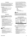
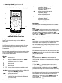
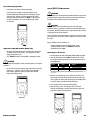
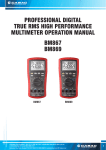
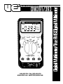
INSTRUCTION MANUAL
DM391/393
1-800-547-5740 • Fax: (503) 643-6322
www.ueitest.com • email: [email protected]
Introduction
The DM391/393 are some of our safest industrial duty meters ever made.
All inputs, ranges and functions protected to 1000 Volts CAT III. Perfect for
HVAC and electrical technicians whose applications require higher
accuracy measurements and True RMS precision. Built in temperature
means one less instrument to bring to the job. The DM393 has convenient
access to battery and fuses without breaking ca l i b ration seals.
Features include
• All inputs, ranges and functions protected to 1000 V CAT III
• True RMS AC Volts and Amps
• Access to battery and fuses without breaking calibration
• Capacitance measurement from 40.00 nF to 100.0 µF
• 0.5% basic DC accuracy
• Frequency measurement to 10 MHz
• 4,000 count backlit display
• Autoranging
• Temperature from -40˚ to 2372˚F
• 4,000 count backlit display
Safety Notes
Before using this meter, read all safety information carefully. In
this manual the word "WARNING" is used to indicate conditions
or actions that may pose physical hazards to the user. The word
"CAUTION" is used to indicate conditions or actions that may
damage this instrument.
• Do not attempt to measure any voltage that exceeds the
ca t e g o rybased rating of this meter
• Do not attempt to use this meter if either the meter or the test
leads have been damaged. Turn it in for repair at a qualified
repair facility
• Ensure meter leads are fully seated by making a quick continuity
check of the leads prior to making voltage measurements
• Keep your fingers away from the test lead’s metal probe
contacts when making measurements. Always grip the leads behind
the finger guards molded into the probes
• Use a current clamp adapter when measuring current that may
exceed 10 amps. See the accessories in UEi’s full-line catalog
• Do not open the meter to replace batteries or fuses while the
probes are connected
WARNING!
Exceeding the specified limits of this meter is dangerous and can
expose the user to serious or possibly fatal injury.
• Voltages above 60 volts DC or 25 volts AC may constitute a
serious shock hazard
• Always turn off power to a circuit (or assembly) under test
before cutting, unsoldering, or breaking the current path Even small amounts of current can be dangerous
• Always disconnect the live test lead before disconnecting the
common test lead from a circuit
DM391/393-MAN
• In the event of electrical shock, ALWAYS bring the victim to
the emergency room for evaluation, regardless of the victim’s
apparent recovery - Electrical shock can cause an unstable heart
rhythm that may need medical attention
• Higher voltages and currents require greater awareness of
physical safety hazards - Before connecting the test leads; turn
off power to the circuit under test; set the meter to the desired
function and range; connect the test leads to the meter first, then
to the circuit under test. Reapply power
• If any of the following indications occur during testing, turn
off the power source to the circuit under test:
• Arcing
• Flame
• Smoke
• Extreme Heat
• Smell of Burning Materials
• Discoloration or Melting of Components
CAUTION!
Do not attempt to remove the meter leads from the circuit under test.
The leads, the meter, or the circuit under test may have degraded to
the point that they no longer provide protection from the voltage and
current applied. If any of these erroneous readings are observed,
disconnect power immediately and recheck all settings and connections
International Symbols
Controls and Indicators
NOTE: Although this manual describes the operation of the DM391 and
DM393, all illustrations and examples assume use of the DM393.
1. Digital Display: Readings are displayed on a digital, 4000
count display.
2. Push-button: Used for special functions and features.
3. Rotary Switch: A l l ows you to switch between any of the
functions or values indicated by the numbers, icons, and group
outlines printed around the rotating dial.
4. Input Terminal For 10A: (20A for 30 seconds) current
measurement function.
5. Input Terminal For Millii-amp and Micro Amps: Current
measurement function.
P. 1
6. Common Input Terminal (ground reference): All
measurement functions.
µA:
Micro-amps AC rms and micro-amps DC
measurements (DM393)
Micro-amps AC and milli-amps DC
measurements (DM391)
mA:
Milli-amps AC rms and milli-amps DC
measurements (DM393)
Milli-amps AC and milli-amps DC
measurements (DM391)
A:
Amperes AC rms and amperes DC
measurements (DM393)
Amperes AC and amperes DC
measurements (DM391)
7. Input Terminal for All Functions: Except current (A, mA, µA).
1
2
Push-Buttons
The buttons activate features that augment the function selected with
the rotary switch.
3
6
4
7
5
Rotary Switch
and Push-button Overv i e w
Turning the Meter On
To turn the meter on, turn the rotary switch from “OFF” to any
switch setting.
Rotary Switch
Turn the meter on by selecting any measurement function. The meter
presents a standard display for that function (range, measurement
units, etc.). Use the “SELECT” push-button to select any rotary switch
alternate function.
When you turn the rotary switch from one function to another, a display
for the new function appears. Button choices made in one function do
not carry over into another function.
Indicators
OFF:
Turns the meter off
V:
(DM393) AC volts RMS and DC volts. Press “SELECT”
push-button to choose AC or DC voltage
V:
(DM391) AC volts
V:
(DM391) DC volts
Ω
:
Access to resistance measurement, continuity test and
diode test
Hz (Duty): Frequency measurement. Duty cycle is also displayed if it
is toggled by the “Hz/Duty” push-button
CAP:
Capacitance measurement
Temp:
(DM393) Temperature measurement in degrees
Centigrade or Fahrenheit. Changing the reading mode
is preset at the factory
DM391/393-MAN
Range
Use the “RANGE” push-button to manually select a range. Press and
hold “RANGE” push-button for two seconds to return the meter to auto
range mode. The meter is in auto range mode when the “AUTO”
indicator is on. The “RANGE” selection function is not available in “Hz”
(Duty), “CAP”, and “Temp” modes.
The range and units are displayed on the LCD.
REL∆
Use this button to set the meter to relative (∆) mode and make relative
measurements. Relative zero allows the user to offset the meter
consecutive measurements with the displaying reading as the reference
value. Practically all displaying readings can be set as relative reference
value. Press the “REL∆” push-button momentarily to activate and to
exit relative zero mode.
Hz/Duty
Press this button to toggle between the “Hz” measurement mode and
the “Duty” measurement mode when the selector switch is set at “Hz”
(Duty), V, µA, mA, and 10A.
Hold
Press this button to turn “HOLD” mode ON and OFF. When the
“HOLD” mode is activated, the meter beeps, freezes the display and
displays the “D.H.” indicator on the LCD. Hold mode freezes the display
for later view.
(Backlight)
Press the “HOLD” ( ) push-button for two seconds to turn the
backlight ON or OFF, when the “HOLD” function is simultaneously
activated with the “D.H.” symbol on the display. Press the “HOLD”
push-button momentarily again to activate the backlight function only.
Select
Press this button to toggle between the DC measurement mode and the
AC measurement mode when the rotary selector switch is set to V
(DM393 only), µA, mA, and 10A. Press the “SELECT” push-button to
cycle through Ω, or measurement modes when the rotary
selector switch is set to Ω, , .
P. 2
Operating Instructions
Voltage (V or V, V) Measurements
Voltage is the difference in electrical potential between two points. The
p o l a r i tyof AC (alternating current) voltage varies over time, while the
p o l a r i tyof DC (direct current) voltage is constant over time. V function
defaults at DC. Press the “SELECT” push-button momentarily to select AC.
Range available in volts function are:
400mV, 4V, 40V, 400V, and 1000V
When measuring voltage, the meter acts like a 10MΩ (10 x 10˚Ω)
impedance in parallel with the circuit. This loading effect can cause
measurement errors in high impedance circuits. In most cases, the
error is negligible (0.1% or less) if the circuit impedance is 10kΩ or less.
WARNING!
To avoid damaging the meter or the equipment under test, remove all
power from the circuit and discharge all high-voltage capacitors before
measuring resistance.
Resistance is an opposition to current flow. The unit of resistance is the
ohm (Ω). The meter measures resistance by sending a small current
through the circuit.
Ranges available in resistance functions are:
4000.0Ω, 4.000 kΩ, 40.00 kΩ, 400.0 kΩ, 4 MΩ, and 40 MΩ
Tips for Measuring Resistance
Tips for Measuring Voltage
• In 400mV range, displayed value may fluctuate while disconnecting
input terminals - This is normal
• AC voltage measuring circuit in DM393 is of root-mean-square
(True RMS) value systems so the meter can accurately measure
AC voltage of non-sinusoidal waveforms including harmonics
caused by various non-linear loads
• To improve the accuracy of DC voltage measurement taken in the
presence of AC voltages (such as, measuring the DC voltage of an
amplifier in the presence of an AC signal), measure the AC volt
age first. Note the just measured AC voltage range and select a
DC voltage rage that is the same or higher than the AC voltage
range - This method improves the DC voltage accuracy by
preventing the input protection circuits from being activated.
WARNING!
To avoid the risk of electrical shock and instrument damage, input
voltages must not exceed 1000 V DC or AC (RMS). Do not attempt to
take any unknown voltage measurement that may be in excess of
1000 V DC or AC (RMS).
Resistance (Ω, , ) Measurement
(Ohms, Diode, and Continuity)
DM391/393-MAN
• Because the meters test current flows through all possible paths
between the test prove tips, the measured value of a resistor in a
circuit is often different from the resistor’s rated value
• The test leads can add 0.1Ω to 0.2Ω of error to resistance
measurements - To measure the resistance of the leads, touch the
probe tips together and read the resistance - If necessary, you can
press the “REL∆” push-button to automatically subtract this value
• The resistance function can produce enough voltage to
forward-bias silicon diode or transistor junctions, causing them to
conduct - Do not use the 40 MΩ range for measuring the in-circuit
resistance to avoid this
• When measuring large resistance, reading may be unstable due to
environmentally induced electrical noise - In this case, directly
connect the resistor to input terminals of the meter or shield the
resistor at potential of the “COM” input terminal to obtain
stable reading
• For resistance above 1 MΩ, the display may take a few seconds
to stabilize - This is normal for high resistance readings
• The meter has a circuit to protect the resistance range from
over-voltage - However, to prevent accidentally exceeding the
protection circuit’s rating and to ensure a correct measurement,
NEVER CONNECT THE LEADS TO A SOURCE OF VOLTAGE
when the rotary switch is set to Ω, , or
functions
P. 3
Diode (
) Test
CAUTION!
Discharge all high-voltage capacitors before testing diodes. Large
value capacitors should be discharged through an appropriate
resistance load.
Use the diode test to check diodes, transistors, silicon controlled rectifiers
( S CRs), and other semiconductor devices. The test sends a current through
a semiconductor junction, then measures the junction’s voltage drop.
Tips for Measuring Frequency
• In frequency, the meter is always autoranging
• When disconnecting the input terminals, the overload sign may be
displayed or the display may unsteadily fluctuate - This is typical
Normal forward voltage drop (forward biased) for a good silicon diode
is between 0.4V to 0.9V. A reading higher than that indicates a leaky
(defective) diode. A zero reading indicates a shorted (defective) diode.
An “OL” indicates an open (defective).
Reverse the test leads connections (reverse biased) across the diode.
The display shows “OL” if the diode is good. Any other readings
indicate the diode is shorted or resistive.
Continuity (
) Test
The continuity function detects intermittent opens and shorts lasting as
little as 1 millisecond. These brief contacts cause the meter to emit a short
beep. This function is convenient for checking wiring connections and
o p e ration of switches. A continuous beep tone indicates a complete wire.
CAUTION!
Using resistance and continuity function in a live circuit will produce
false results and may damage the instrument. In many cases the
suspicious components must be disconnected from the circuit under
test to obtain accurate results.
Frequency (Hz) Measurement
Frequency is the number of cycles a signal completes each second. The
meter measures the frequency of a voltage or current signal by counting
the number of times the signal crosses a threshold level each second. To
measure the frequency of a voltage or current signal, press the “Hz/D u t y”
push-button momentarily while measuring volts or currents.
Duty Cycle Measurement
D u ty Cycle (or Duty Factor) is the percentage of time a signal is above or
b e l ow a trigger level during one cycle. The duty cycle mode is optimized
for measuring the ON or OFF time of logic and switching signals. Systems
such as electronic fuel injection systems and switching power supplies are
controlled by pulses of varying width, which can be checked by measuring
d u ty cy c l e .
Press the “Hz/Duty” push-button to toggle between the Hz mode and the
D u ty Cycle mode when the rotary selector knob is set to “Hz” (Duty),
V, µA, mA, and 10A.
Capacitance Measurement
CAUTION!
To avoid damaging the meter or the equipment under test, remove all
power from the circuit and discharge all high-voltage capacitors before
measuring capacitance. Large value capacitors should be discharged
through an appropriate resistance load. Use the DC voltage function to
confirm that the capacitor is discharged.
Capacitance is the ability of a component to store an electrical charge.
The unity of capacitance is the farad (F). Most capacitors are in the
nanofarad (nF) to microfarad (µF) range.
The available capacitance ranges are 40nF, 400nF, 4µF, 40µF, and 100µF.
The available frequency ranges are: 5Hz, 50Hz, 500Hz, 5kHz, 50kHz,
500kHz, 5MHz, and 10MHz.
DM391/393-MAN
P. 4
Tips for Measuring Capacitance
Current (µA, mA, 10A) Measurement
• In capacitance, the meter is always autoranging
• In 40nF range, the readings are probably unstable due to
environmentally induced electrical noise and floating capacity
of the test leads. Therefore, directly connect the object to be
measured to the input terminals. Use “REL∆” in this range for
accurate measurement - The meter will display 0.33 nF with
no connectors
WARNING!
Never attempt an in-circuit current measurement where the open-circuit
potential to earth is greater than 1000V. You may damage the meter or
be injured if the fuse blows during such a measurement.
CAUTION!
Check the meter fuses before measuring current. Use the proper
terminals, functions, and range for current measurements. Never place
the probes in parallel with any circuit or component when the test leads
are plugged into the current terminal.
Current is the flow of electrons though a conductor. To measure current
you must open the circuit under test, then place the meter in series with
the circuit.
Ranges available in current functions are:
Temperature (Temp) Measurements (DM393 only)
• The meter comes with temperature reading in either Centigrade
or Fahrenheit preset at the factory - The reading mode can be
changed at the factory only
*The “SELECT” function is not available in temperature mode.
WARNING!
DO NOT apply thermocouple to circuits exceeding 30V rms, 42.4V peak
or 60V DC.
• Be sure to insert the banana plug K-type temperature bead probe
with correct + - polarities - You can also use a thermocouple
probe adapter (optional purchase) to adapt other standard
K-type thermocouple probes
400.0µA, 4000µA, 40.00mA, 400.0mA, 4.000A, 10.00A
The meter defaults at DC. Press “SELECT” push-button
momentarily to select “AC”.
Measuring AC or DC Current
1. Turn off power to the circuit and discharge all high-voltage capacitors.
2. Insert the black lead into the “COM” terminal and the red lead
into an input terminal appropriate for the measurement range as
the following table.
Range
Input
mAµA
mAµA
10A
Ranges
400.0 µA, 4000 µA
400.0 µA, 4000 µA
4.000 A, 10.00 A
*To avoid blowing the meter’s 440 mA fuse, use the mAµA terminal only if you are sure the current is
less than 400 mA.
3. Open the current path to be tested. Touch the red probe to the
more positive side of the break and touch the black probe to the
more negative side of the break. (Reversing the leads will produce
a negative reading, but will not damage the meter).
4. Turn on power to the circuit and read the display.
5. After measuring current, turn off power to the circuit and
discharge at high-voltage capacitors. Disconnect the meter and
restore the circuit to normal operation.
DM391/393-MAN
P. 5
Tips for Measuring Current
• When measuring a 3-phase system, special attention should be taken
to the phase to phase voltage which is significantly higher than the
phase to earth voltage. To avoid exceeding the voltage rating of the
protection fuse(s) accidentally, always consider the phase to phase
voltage as the working voltage for the protection fuse(s).
• When measuring current, the meter’s internal shunt resistors
develop a voltage across the meter’s terminals called “burden
voltage”. This voltage drop may affect precision circuit
or measurements.
Auto/Manual Range Operation
Press the “RANGE” push-button momentarily to select manual-ranging
in volts, ohms, and current measurement functions, and the meter will
remain in the range it was in, when the LCD annunciator “AUTO”
turns off.
Cleaning
Periodically clean your meter’s case using a damp cloth. DO NOT use
abrasive, flammable liquids, cleaning solvents, or strong detergents as
they may damage the finish, impair safety, or affect the reliability of the
structural components.
Battery, Fuse and Test Load Replacement
Always use a fresh replacement battery of the specified size and type.
Immediately remove the old or weak battery from the meter and
dispose of it in accordance with your local disposal regulations. Batteries
can leak chemicals that corrode electronic circuits. If your meter is not
going to be used for a month or more, remove and store the battery in
a place that will not allow leakage to damage other materials. This
meter uses a single standard 9V battery (NEDA 1604, JIS006P, IEC 6F
22), a 1000V/440 mA IR 10 kA fast acting F fuse for mAµA current input,
and a 1000V/11A IR 10 Ka fast acting F fuse for A current input
Press the button momentarily again to step through the ranges.
Press and hold the “RANGE” push-button for 2 seconds to resume
auto-ranging.
WARNING!
Disconnect the test leads from the circuit under test and from the meter
prior to removing or installing batteries.
Note: Manual-ra n ging feature is not available in Hz (Duty), CAP, TEMP,
and
functions.
To install a new battery, follow these procedures:
Auto Power-Off
The Auto-Power-Off feature automatically turns the meter off to extend
battery life after approximately 30 minutes of no activities. To turn on
the meter after Auto-Power-Off, turn the rotary switch from OFF to any
function (ON).
Maintenance
Periodic Service
WARNING!
Repair and service of this instrument is to be performed by qualified
personnel only. Improper repair or service could result in physical
degradation of the meter. This could alter the protection from
electrical shock and personal injury this meter provides to the
operator. Perform only those maintenance tasks that you are
qualified to do.
These guidelines will help you attain long and reliable service from
your meter:
• Calibrate your meter annually to ensure it meets original
performance specifications
• Keep your meter dry. If it gets wet, wipe dry immediately.
Liquids can degrade electronic circuits
• Whenever practical, keep the meter away from dust and
dirt that can cause premature wear
• Although your meter is built to withstand the rigors of daily
use, it can be damaged by severe impacts. Use reasonable
caution when using and storing the meter
DM391/393-MAN
1. Turn off the meter.
2. Remove the rubber boot from the meter, starting at the top.
3. Place meter face down on a clean cloth.
4. Remove the screws from the rear case. Two machined screws
fasten the bottom and two self-tapping screws fasten the top.
5. Separate the two halves to expose the battery.
6. Remove and discard the old battery. Always dispose of old batteries
promptly in a manner with local disposal regulations.
WARNING!
Under no circumstances should you expose batteries to extreme heat or
fire as they may expose and cause injury.
7. Place a fresh 9V battery in the battery clip.
8. Reassemble the meter.
Troubleshooting
If the meter fails to operate even with the battery or fuse replacements,
check twice according to operating procedures as described in this manual.
If the meter’s V/ input terminal was subjected to high voltage transient
( caused by lightning or switching surge to the system) by accident or
abnormal operating conditions, the series fusible resistors will be blown in
order to protect the user and the meter. Most measuring functions through
this terminal will then be open circuit.
In this case, the series fusible resistors and the spark gaps should be
replaced by qualified personnel. Refer to the LIMITED WA RRA NTY &
LIMITATIONS OF L I A BIL ITY section for obtaining warranty or
repairing service.
P. 6
Specifications
Backlight
Fast autoranging
Safety and Compliance
Maximum voltage between any
terminal and the ground
Compliances
Certifications
Surge protection
Fuse protection fro mA or µA inputs
Fuse protection for A input
Operating temperature
Storage temperature
Temperature coefficient
Relative humidity
Altitude
Complies with CSA C22.2 No 1010.1-92,
NASI/ISA-S82, 01-94 to 1000 V
overvoltage category III
UL & cUL standard UL 3111-1
listed CE-marking certified
8kV peak per IEC 1010.0-92
1000 V/440mA IR 10kA FAST fuse
1000 V/11A IR 10kA FAST fuse
Digital -4000 counts display;
updates 5 times/sec.
32˚ to 104˚F (-0˚ to 40˚C)
-4˚ to 140˚F (-20˚ to 60˚C)
Nominal 0.15 x (specified accuracy)/˚C @
(0˚ to 8˚C or 28˚ to 40˚C),
or otherwise specified
0% to 80% @ (32˚ to 95˚F)
0% to 70% @ (95˚ to 104˚F)
Operating - up to 6,500 feet
Storage - 32,000 feet
Specifications
Battery type
Battery life
Shock degree
Pollution degree
Electromagnetic compatibility
(EMC)
Size
Weight
Warranty
Calibration interval
For clear readings in poorly lit areas
Meter automatically selects the best
range momentarily
Holds readings on display
Beeper sounds
Battery or fuse replaceable without
voiding calibration
Protective holster features
1000 V AC/DC
Physical Specifications
Display
Feature Summary
Single 9V battery - NEDA 1604, JIS
006P ir IEC 6F 22
250 hrs. typical (w/backlight off) DM393
250 hrs. typical (w/backlight off) DM391
Per MIL-T-PRE 28800 for Class II
instruments
2
Susceptibility - commercial limits for
EN 50082-1
Emissions - commercial limits for
EN 50081-1
1.6 x 3.6 x 6.8 inches
13.6 oz.
Five (5) year limited warranty
One (1) year recommended
HOLD
Continuity/open test
Battery/fuse access door
High-impact over-molded case
Electrical Specifications
Accuracy is given as ±([% of reading] + [number of digits]) at 64˚ to 82˚F
with relative humidity up to 80%, for period of one year after
calibration. True RMS responding accuracies are specified from 5% to
100% of range or otherwise specified; Crest Factor < 3:1 at full scale
and < 6:1 at half scale.
Range
Resolution
Accuracy
DM391
400mV
4V
40V
400V
1000V
100µV
1mV
10mV
100mV
1V
DM393
0.5% + 2
0.5% + 2
0.75% + 3
0.75% + 3
NMRR
>60db @ 50/60 Hz
CMRR
(Common Mode Rejection Ratio)
>120db @ DC, 50/60 Hz, Rs = 1kΩ
Input Impedance
10 MΩ, 30 pF nominal
(50 MΩ, 100 pF nominal for 400
mV range)
AC Voltage
Range
Resolution
400mV
4V
40V
400V
1000V
100µV
1mV
10mV
100mV
1V
Accuracy
40 Hz - 400 Hz
400 Hz - 1 kHz
1 kHz - 20 kHz
DM391
DM393
DM393
2.0% + 10
2.0% + 10
0.75% + 3 0.75% + 3
1.0% + 5
1.0% + 5
2.0% + 3
2.0% + 5*1
-
CMRR
(Common Mode Rejection Ratio)
>60db @ DC Hz, Rs = 1kΩ
Input Impedance
10 MΩ, 30 pF nominal
(50 MΩ, 100 pF nominal for 400
mV range)
*1Accuracy for 400 Hz to 1 kHz
DM391/393-MAN
P. 7
DC Current
Range
Frequency and Duty Cycle
Resolution
Accuracy
DM391
400µA
4000µA
40mA
400mA
4A
10A
0.1µA
1µA
10µA
100µA
1mA
10mA
1.0% + 2
1.0% + 2
1.5% + 5
1.5% + 5
AC Current
Range
Resolution
Accuracy
40 Hz - 400 Hz
DM391
DM393
400µA
4000µA
40mA
400mA
4A
10A
0.1µA
1µA
10µA
100µA
1mA
10mA
400Ω
4000Ω
40kΩ
400kΩ
4MΩ
10MΩ
1.0% + 5
1.0% + 5
1.5% + 10 1.5% + 10
1.5% + 5
2.0% + 10
Resolution
0.001Hz
0.01Hz
0.1Hz
1Hz
10Hz
100Hz
1kHz
10kHz
0.1%
DM393
1.0% + 5
Range
-40˚ to 14˚F
(-40˚ to -10˚C)
14˚ to 752˚F
(-10˚ to -400˚C)
752˚ to 2372˚F
(400˚ to 1300˚C)
0.5% + 3
1.0% + 5
1.5% + 10
0.5% + 3
1.0% + 5
1.5% + 10
: the beeper sounds if the measured resistance is lower
than 10Ω, and turns off when greater than about 60Ω
: <1 msec.
V
(4V tp 1000V)
µA
(400µA to 400mA)
mA
(40mA to 400mA)
A
(4.0A to 10A)
Sensitivity
5Hz - 1MHz, > 250mV
1MHz - 10MHz, > 350mV
0.5Hz to 500kHz (pulse width > 2µ sec.)
(0.1% + 0.05% per khz + 1 count) for 5 V input
(Logic signals only)
Range
Resolution
4V
2%
Test Current
(Typical)
0.25mA
Open Circuit Voltage
mA/µA
<1.5V DC
10A
Capacitance
Resolution
10pF
100pF
1nF
10nF
100nF
DM391/393-MAN
Resolution
1˚F
1˚C
1˚F
1˚C
1˚F
1˚C
Accuracy
3% ± 5˚F
(3% ± 5˚C)
1% ± 3˚F
(1% ± 3˚C)
3% of reading
(3% of reading)
Minimum Sensitivity (RMS Sine Wave)
40Hz to 10kHz
10Hz to 20kHz
500mV
500mV
> 15% F.S. of AC range
Not Specified
> 15% F.S. of AC range
Not Specified
> 15% F.S. of AC range
Not Specified
Burden Voltage (A, mA, µA)
Function
Diode Test
40nF
400nF
4µF
40µF
100µF
Minimum frequency:
0.05% + 3 0.05% + 3 0.5Hz
Frequency Counter Sensitivity
Range
Continuity
Range
Remark
Accuracy
DM391
1.0% + 5
Open circuit voltage: <1.3 V DC
Response time
5Hz
50Hz
500Hz
5kHz
50kHz
500kHz
5MHz
10MHz
0.1% to
99.9%
Accuracy
DM391
DM393
Temperature (DM393)
0.1Ω
1Ω
10Ω
100Ω
1kΩ
10kΩ
Audible threshold
Resolution
400 Hz - 10 kHz
DM393
Resistance
Range
Range
DM393
Range
400µA
4000µA
40mA
400mA
4A
10A
Burden Voltage (typical)
150µV/µA
150µV/µA
3.3mV/mA
3.3mV/mA
0.03V/A
0.03V/A
Accuracy
DM391
DM393
2.5% + 10
2.5% + 10
Electromagnetic Compatibility (EMC)
The meters meet EN 61326: 1997 A1: 1998.
P. 8
Glossary of Terms
Average sensing RMS calibrated: RMS (Root-Mean-Square) is the
term used to describe the effective or equivalent DC value of an AC
signal. most digital multimeters use average sensing RMS calibrated
technique to measure RMS values of AC signals. This technique is to
obtain the average value by rectifying and filtering the AC signal. The
average value is ten scaled upward (that is, calibrated) to read the RMS
value of a sine wave. in measuring pure sinusoidal waveform. This
technique is fast, accurate, and cost effective. However, in measuring
non-sinusoidal waveforms, significant errors can be introduced because
of different scaling factors relating average to RMS values.
True RMS: True RMS is a term which identifies a DMM that accurately
responds to the effective RMS value regardless of the waveform shapes
such as square, sawtooth, triangle, pulse trains, spikes, and transient
glitches as well as distorted waveforms with the presence of harmonics.
Non-sinusoidal waveforms may cause:
• Overheated transformers, generator and motors to burn out
faster than normal
• Circuit breakers to trip prematurely
• Fuses to blow
• Neutrals to be overheated due to the triplen harmonics present
on the neutral
• Bus bars and electrical panels to vibrate
Crest Factor: Is the ratio of the Crest (instantaneous peak) value to the
True RMS value, which is commonly used to define the dynamic range
of a True DMM. A pure sinusoidal waveform has a Crest Factor of 1.414.
A badly distorted sinusoidal waveform normally has a much higher
Crest Factor.
NMRR: (Normal Mode Rejection Ratio) is the DMM’s ability to
reject unwanted AC noise effect which can cause inaccurate DC
measurements. NMRR is typically specified in terms of db (decibel). The
meter has a NMRR specification of > 60db at 50Hz/60Hz, which means
a good ability to reject the effect of AC noise in DC measurements.
CMRR: (Common Mode Rejection Ratio) common mode voltage is
voltage existing on both the COM and Voltage input terminals of a
DMM, with respect to ground. CMRR is a DMM’s ability to reject
common mode voltage effect which can cause digit rattle or offset in
voltage measurements. The meter has a CMRR specification of > 60db
at DC to 60Hz in AC volts measurement function and > 120db at DC,
50Hz and 60Hz in DC volts measurement function.
Burden Voltage: Burden voltage is a voltage drop across the input
terminals of a current measuring device, caused by internal shunt
resistance. Burden voltage contributes measurement error, and should
be as low as practical.
Temperature Coefficient: Is a factor used to calculate the change in
indication or output of an instrument with changes in temperature.
Uncompensated changes in temperature contribute uncertainty by an
amount determined by the temperature coefficient to instrument.
DM391/393-MAN
P. 9
DM391/393
Digital Multimeter
Limited Warranty
The DM391/393 is warranted to be free from defects in materials and workmanship for a
period of five years from the date of purchase. If within the warra n ty period your instrument
should become inoperative from such defects, the unit will be repaired or replaced at UEi’s
option. This warra n ty covers normal use and does not cover damage which occurs in shipment or
failure which results from alteration, tampering, accident, misuse, abuse, neglect or improper
maintenance. Batteries and consequential damage resulting from failed batteries are not
covered by warra n ty.
Any implied warranties, including but not limited to implied warranties of merchantability
and fitness for a particular purpose, are limited to the express warranty. UEi shall not be
liable for loss of use of the instrument or other incidental or consequential damages,
expenses, or economic loss, or for any claim or claims for such damage, expenses or
economic loss. A purchase receipt or other proof of original purchase date will be required
before warra n ty repairs will be rendered. Instruments out of warra n ty will be repaired (when
repairable) for a service charge. Return the unit postage paid and insured to:
1-800-547-5740 • FAX: (503) 643-6322
www.ueitest.com • Email: [email protected]
This warranty gives you specific legal rights. You may also have other rights which vary from
state to state.
PLEASE
RECYCLE
Copyright © 2007 UEi
DM391/393-MAN 1/07