1
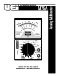
INSTRUCTION MANUAL
M110A
1-800-547-5740 • Fax: (503) 643-6322
www.ueitest.com • email: [email protected]
Introduction
The M110A, in addition to high-resolution voltage and ohms scales
needed for electrical troubleshooting also includes the features that
help you maintain and troubleshoot HVAC/R systems. Features like DC
millivolts and microamps let you troubleshoot flame safeguard circuits
and the millivolts function helps you evaluate heat anticipators.
Features include
• 21 ranges
• 600 Volts AC and 300 Volts DC
• 2 Megohm resistance
• High resolution DC µA for flame safeguard testing
• DC millivolt scale allows use of adapters
• Color-coded and mirrored scale plate
Safety Notes
Before using this meter, read all safety information carefully. In
this manual the word "WARNING" is used to indicate conditions
or actions that may pose physical hazards to the user. The word
"CAUTION" is used to indicate conditions or actions that may
damage this instrument.
• Always follow industry standard safety practices including protective
clothing, gloves and safety glasses when appropriate
• Do not attempt to measure any voltage that exceeds the
ca t e g o rybased rating of this meter
• Do not attempt to use this meter if either the meter or the test
leads have been damaged. Turn it in for repair at a qualified
repair facility
• Ensure meter leads are fully seated by making a quick continuity
check of the leads prior to making voltage measurements
• Keep your fingers away from the test lead’s metal probe
contacts when making measurements. Always grip the leads behind
the finger guards molded into the probes
• Use a current clamp adapter when measuring current that may
exceed 10 amps. See the accessories in UEi’s full-line catalog
• Do not open the meter to replace batteries or fuses while the
probes are connected
WARNING!
Exceeding the specified limits of this meter is dangerous and can
expose the user to serious or possibly fatal injury.
• Voltages above 60 volts DC or 25 volts AC may constitute a
serious shock hazard
• Always turn off power to a circuit (or assembly) under test
before cutting, unsoldering, or breaking the current path Even small amounts of current can be dangerous
• Always disconnect the live test lead before disconnecting the
common test lead from a circuit
• In the event of electrical shock, ALWAYS bring the victim to
the emergency room for evaluation, regardless of the victim’s
apparent recovery - Electrical shock can cause an unstable heart
rhythm that may need medical attention
M110A-MAN
• Higher voltages and currents require greater awareness of
physical safety hazards - Before connecting the test leads; turn
off power to the circuit under test; set the meter to the desired
function and range; connect the test leads to the meter first, then
to the circuit under test. Reapply power
• If any of the following indications occur during testing, turn
off the power source to the circuit under test:
• Arcing
• Flame
• Smoke
• Extreme Heat
• Smell of Burning Materials
• Discoloration or Melting of Components
CAUTION!
Do not attempt to re m ove the meter leads from the circuit under test.
The leads, the meter, or the circuit under test may have degraded to
the point that they no longer provide protection from the voltage and
c u r rent applied. If any of these erroneous re a d i n gs are observed,
disconnect power immediately and recheck all settings and connections.
Controls and Indicators
1. Selector Switch: Is used to select the circuit function and range.
It is good practice to start with the highest range setting of the
“SELECTOR” switch for a particular function if the magnitude of
the function is unknown.
2. Ω ADJ: The “Ω ADJ” control is used on the OHMS function. The
purpose of this control is to calibrate the M110A on the particular
range selected (Rx1, Rx10, etc.)
3. Mechanical Zero Adjust: Is a plastic screw located on the meter
face just beneath the “LOCK” switch. This adjustment is used to set
the pointer to the zero index mark at the left side of the scale plate.
4. Input Jacks:
COM (-): The black test lead is used to connect this jack to the
negative, or common, side of the circuit test.
VΩM (+): The red test lead is used to connect this jack to the
positive side of the circuit test.
DC 12 0 0 V: This jack is used for the 0 - 1200 V DC (0 - 12 K V DC with
optional probe) range of the M110A. The red (positive) test lead is
connected to this jack.
3
2
4
1
P. 1
Operating Instructions
Color Coding
The meter scale plating and front panel are color coded. The DC Voltage
and DC Current meter scale and SELECTOR switch positions are in BLACK.
The OHMS meter scale and SELECTOR switch positions are in GREEN. The
AC Voltage meter scales and SELECTOR switch positions are in RED.
To provide an uncrowded easy-to-read meter scale plate a single meter
s cale may be used for more than one position of the SELECTOR switch.
For example, the meter scale numerals 0 - 30 are used for the follow i n g
positions of the SEL E C TO R switch: 300 V DC, 3 V DC, 300 mV DC, 0.03 mA
DC and 300 V AC. If the SELECTOR switch range is 300, divide the sca l e
numerals by ten.
Measuring DC Voltage
Set the SELECTOR switch to the appropriate range. Always start with the
300 V DC position if unsure of the magnitude of voltage present. Connect
the black test lead to the “COM” jack and to the negative side of the
circuit under test. Connect the red test lead to the “+VΩM” jack and to
the positive side of the circuit under test. Read the voltage on the black
meter scale corresponding to the SELECTOR switch setting. When
measuring DC voltage on the 1200 V DC range set the SELECTOR switch
to the 300 V Dc position and connect the red test lead to the 1200 V DC
jack. The black test lead is connected as before.
Measuring DC Current
Set the SELECTOR switch to the appropriate range. Always start with the
600 mA DC position if unsure of the magnitude of current present.
(Note: 0.03 mA DC = 30 µA DC and 0.06 mA DC = 60 µA). When
taking current measurements the meter must be connected in SERIES
with the circuit, or circuit element, under test. Break the connection at
the point at which current is to be measured. Place the M110A in series
with the circuit by connecting the black test lead to the “COM” jack
and to the lower voltage side of the circuit. Connect the red test lead
to the “+VΩM” jack and to the higher voltage side of the circuit. Read
the current on the black meter scale corresponding to the SELECTOR
switch setting.
Set the SELECTOR switch to the appropriate range. Connect one test
lead to the “COM” jack and the other test lead to the “ +VΩM” jack.
Touch the free ends of the test leads together. The pointer will swing to
the right hand side of the scale. Adjust the “Ω A D J” control until the
pointer is set on the green numeral 0. (Note: If this adjustment cannot
be made refer to the MAINTENANCE section). Rezero the M110A each
time the OHMS setting of the SELECTOR switch is changed. To make the
resistance measurement, connect the free ends of the test leads across
the element to be measured. The measured resistance value will be the
green numeral indicated on the OHMS scale times the multiplier on the
SELECTOR switch. For example, if the pointer is on the numeral 4, and
the SELECTOR switch is set on Rx10, the resistance is 40 ohms (4 Ω x 10
= 40 Ω).
Continuity tests are normally made to test a wire, or element, to see if it
is unbroken. Because continuity tests involve low values of resistance,
the SELECTOR switch should be set on the Rx1 position.
Testing Diodes / Transistors
A simple check of diode or transistor quality may be made with the
M110A. Using the same test procedure as for measuring resistance,
connect one test lead to one end of the diode and the other test lead to
the other end of the diode. Note the resistance reading. Then reverse
the test leads and again note the reading. If the two readings differ by a
factor of ten then the diode, (or transistor junction) is probably good.
If the readings are approximately the same then the diode is shorted.
If a reading cannot be obtained in either direction, the diode is
probably between the base and emitter leads, or between the base
and collector leads.
Measuring AC Voltage
Set the SELECTOR switch to the appropriate range. Always start with the
600 V AC position if unsure of the magnitude of voltage present. Connect
the test leads to the “COM” jack and the “+VΩM” jack and to the circuit
under test. Read the voltage on the red meter scale corresponding to the
SEL E C TOR switch setting. Use the lower red scale marked 6 V ONLY when
the SELECTOR switch is set on 6 V AC. For all other V AC measurements
use the upper red scale marked 30 V UP.
Measuring Resistance
Maintenance
WARNING!
Remove all power to the circuit under test when making resistance
measurements. If any voltage is present in the test circuit an erroneous
reading will result ad the 6/10A fuse may open.
NOTE: When the M110A is set on the Rx1 OHM range, the accuracy
of the measurements can be degraded if there is dirt on the probe
tips. If the measurements are questionable, clean the tips and input
connections of the probes and the input jacks of the M110A.
M110A-MAN
Periodic Service
WARNING!
Repair and service of this instrument is to be performed by qualified
personnel only. Improper repair or service could result in physical
degradation of the meter. This could alter the protection from
electrical shock and personal injury this meter provides to the
operator. Perform only those maintenance tasks that you are
qualified to do.
P. 2
These guidelines will help you attain long and reliable service from
your meter:
• Calibrate your meter annually to ensure it meets original
performance specifications
• Keep your meter dry. If it gets wet, wipe dry immediately.
Liquids can degrade electronic circuits
• Whenever practical, keep the meter away from dust and dirt
that can cause premature wear
• Although your meter is built to withstand the rigors of daily use,
it can be damaged by severe impacts. Use reasonable caution
when using and storing the meter
Cleaning
Periodically clean your meter’s case using a damp cloth. DO NOT use
abrasive, flammable liquids, cleaning solvents, or strong detergents as
they may damage the finish, impair safety, or affect the reliability of the
structural components.
Fuse Replacement
The 6/10A, 0.5 ohm, fuse is in series with the “+VΩM” input jack. If this
fuse is open none of the circuit functions will work. When replacing the
fuse be sure to replace it with a fuse of the same current rating and
internal resistance. The use of a fuse with a different internal resistance
may cause the accuracy of the OHMS scale to be off. Remove the single
screw in the rear of the case for access to the fuse.
Mechanical Zero Adjust
The pointer is set to register 0 at the left hand edge of the scale when
there is no input to the M110A and it is laying face up on a flat surface.
If the pointer does not register 0, it may be reset to that position by
carefully adjusting the plastic screw in the meter face, just below the
green “FUSE PROTECTED OHMS CIRCUIT” label.
Specifications
Clean the input terminals as follows:
1. Turn the meter off and remove all test leads.
Ranges
DC Millivolts
0 - 60, 300, 1200m V
2. Shake out any dirt that may be in the terminals.
DC Volts
0 - 3, 12, 60, 300, 1200 V
3. Soak a new swab with alcohol and work the swab around in
each terminal.
DC Microamps
0 - 30, 60µ A
DC Milliamps
0 - 60, 600m A
OHMS
0 - 200Ω, 2K, 20K, 2M
AC Volts
0 - 6, 30, 60, 300, 600 V
Temperature
0 - 60, 300, 500˚F
Battery Replacement
The purpose of the batteries is to supply power to the circuit under test
while making resistance measurements. Eventually the batteries will age
to the point where it will not be possible to zero the meter with the
“Ω ADJ” control. When this happens the batteries should be replaced.
The two 1.5V size “AA” batteries are used only on the Rx1, Rx10 and Rx100
setting of the SELECTOR switch and should be replaced as a pair. The 9 V
battery affects only the Rx10K setting of the SELECTOR switch. It may not
be necessary to replace it when replacing the two 1.5V batteries. Observ e
the proper battery polarity when replacing batteries. It is recommended
that all batteries be removed if the M110A is not to be used for a long
period of time. Remove the single screw in the rear of the case for access
to the batteries.
(0 - 12,000 V with optional probe)
Accuracy
DC
±3% of full scale
OHMS
±3% of scale length
AC
±4% of full scale
Temperature
±2 divisions
General
Input Impedance
30K/V DC, 15K/V AC
Batteries
Two 1.5V, size “AA” (NEDA #15D) batteries
One 9 V (NEDA #1604) battery
Fuse
6/10A (0.5 ohm internal resistance) 3AG series
Note: To maintain calibration accuracy and instrument
protection, replacement fuse must be of the proper
current and resistance value.
WARNING!
Disconnect the test leads from the circuit under test and from the meter
prior to removing or installing batteries.
WARNING!
Under no circumstances should you expose batteries to extreme heat or
fire as they may explode and cause injury.
M110A-MAN
Optional Accessories
Optional
Battery 1.5V, size “AA” . . . . . . . . . . . . . . . . . . . . . . . . . . . . . . . . .AB1
Battery 9V . . . . . . . . . . . . . . . . . . . . . . . . . . . . . . . . . . . . . . . . . . .AB9
Fuse 6/10A, 0.5Ω (pkg. of 3) . . . . . . . . . . . . . . . . . . . . . . . . . . . .AF10
Test leads, (set) . . . . . . . . . . . . . . . . . . . . . . . . . . . . . . . . . . . . . . .ATL50
Test leads, rubber (set) . . . . . . . . . . . . . . . . . . . . . . . . . . . . . . . . .ATL25
Alligator clip adapters, insulated (pr) . . . . . . . . . . . . . . . . . . . . .AAC
High voltage probe (12K V DC) . . . . . . . . . . . . . . . . . . . . . . . . . .A12K
Carrying case . . . . . . . . . . . . . . . . . . . . . . . . . . . . . . . . . . . . . . . .AC110
Temperature adapter . . . . . . . . . . . . . . . . . . . . . . . . . . . . . . . . . .TA2K
P. 3
M110A
Analog Multimeter
Limited Warranty
The M110A is warranted to be free from defects in materials and workmanship for a period of
three years from the date of purchase. If within the warra n ty period your instrument should
become inoperative from such defects, the unit will be repaired or replaced at UEi’s option.
This warra n ty covers normal use and does not cover damage which occurs in shipment or
failure which results from alteration, tampering, accident, misuse, abuse, neglect or improper
maintenance. Batteries and consequential damage resulting from failed batteries are not
covered by warra n ty.
Any implied warranties, including but not limited to implied warranties of merchantability
and fitness for a particular purpose, are limited to the express warranty. UEi shall not be
liable for loss of use of the instrument or other incidental or consequential damages,
expenses, or economic loss, or for any claim or claims for such damage, expenses or
economic loss. A purchase receipt or other proof of original purchase date will be required
before warra n ty repairs will be rendered. Instruments out of warra n ty will be repaired (when
repairable) for a service charge. Return the unit postage paid and insured to:
1-800-547-5740 • FAX: (503) 643-6322
www.ueitest.com • Email: [email protected]
This warranty gives you specific legal rights. You may also have other rights which vary from
state to state.
PLEASE
RECYCLE
Copyright © 2007 UEi
M110A-MAN 1/07