1
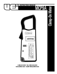
INSTRUCTION MANUAL
MCP4
1-800-547-5740 • Fax: (503) 643-6322
www.ueitest.com • email: [email protected]
Introduction
The MCP4 includes 5 amperage ranges to give you precise readings on
low or high amp circuits. It also includes volts and ohms readings to
give you the complete picture of your circuit path.
Features include
• 10 ranges
• 300 Amps AC
• 750 Volts AC
• Resistance to 1000 ohms
• Color-coded, high res scale-plate
• Pointer-lock switch (data hold)
• 1-1/4” jaw capacity
Safety Notes
Before using this meter, read all safety information carefully. In
this manual the word "WARNING" is used to indicate conditions
or actions that may pose physical hazards to the user. The word
"CAUTION" is used to indicate conditions or actions that may
damage this instrument.
• Always follow industry standard safety practices including protective
clothing, gloves and safety glasses when appropriate
• Do not attempt to measure any voltage that exceeds the
ca t e g o rybased rating of this meter
• Do not attempt to use this meter if either the meter or the test
leads have been damaged. Turn it in for repair at a qualified
repair facility
• Ensure meter leads are fully seated by making a quick continuity
check of the leads prior to making voltage measurements
• Keep your fingers away from the test lead’s metal probe
contacts when making measurements. Always grip the leads behind
the finger guards molded into the probes
• Use a current clamp adapter when measuring current that may
exceed 10 amps. See the accessories in UEi’s full-line catalog
• Do not open the meter to replace batteries or fuses while the
probes are connected
WARNING!
Exceeding the specified limits of this meter is dangerous and can
expose the user to serious or possibly fatal injury.
• Voltages above 60 volts DC or 25 volts AC may constitute a
serious shock hazard
• Always turn off power to a circuit (or assembly) under test
before cutting, unsoldering, or breaking the current path Even small amounts of current can be dangerous
• Always disconnect the live test lead before disconnecting the
common test lead from a circuit
• In the event of electrical shock, ALWAYS bring the victim to
the emergency room for evaluation, regardless of the victim’s
apparent recovery - Electrical shock can cause an unstable heart
rhythm that may need medical attention
MCP4-MAN
• Higher voltages and currents require greater awareness of
physical safety hazards - Before connecting the test leads; turn
off power to the circuit under test; set the meter to the desired
function and range; connect the test leads to the meter first, then
to the circuit under test. Reapply power
• If any of the following indications occur during testing, turn
off the power source to the circuit under test:
• Arcing
• Flame
• Smoke
• Extreme Heat
• Smell of Burning Materials
• Discoloration or Melting of Components
CAUTION!
Do not attempt to remove the meter leads from the circuit under test.
The leads, the meter, or the circuit under test may have degraded to
the point that they no longer provide protection from the voltage and
current applied. If any of these erroneous readings are observed,
disconnect power immediately and recheck all settings and connections
Controls and Indicators
1. Selector Switch: Is used to select the circuit function and range.
It is good practice to start with the highest range setting of the
“SELECTOR” switch for a particular function if the magnitude of
the function is unknown.
2. OHM ADJ: Used only on the “OHMS” function. The purpose of
this control is to calibrate the MCP9A to compensate for changes
in the voltage of the internal 1.5 V battery.
3. Lock Switch: Is located at the upper left side of the scale plate. It
is used to secure the pointer at the last reading when measurements
must be made in a confined or difficult-to-read location.
4. Mechanical Zero Adjust: Is a plastic screw located on the meter
face just beneath the “LOCK” switch. This adjustment is used to set
the pointer to the zero index mark at the left side of the scale plate.
5. Input Jacks: Are a special twist lock banana type. The twist lock
feature prevents the test leads from accidentally separating from the
jacks during the taking of AC Voltage measurements.
6. Volts: The jacks located on the left side of the MCP4 are used for
taking AC and DC Voltage measurements.
7. OHMS: The jacks located on the right side of the MCP4 are used
for taking resistance measurements.
P. 1
Operating Instructions
Measuring AC Current
When measuring current, always be sure the “SEL ECTOR” switch is set
to the appropriate AMP range. When in doubt, always use the highest
current range first. The switch can always be reset to a lower range for a
more precise reading. AC current measurements are made on the red
A MP scales on the scale plate.
Clamp the jaw of the MCP4 around a single circuit wire.
NOTE: Clamp only one wire at a time for measurement. If two or more
wires are clamped together, the tester will not read.
Measuring Temperature
Set the MCP4 to the “R x 10 0 / TEMP” range. Insert both of the black plugs
on the temperature probe into the “OHM” input jacks on the MCP4.
Adjust the green “OHM ADJ” control on the left side of the instrument
until the pointer is set on the green numeral 0.
NOTE: If this adjustment cannot be made refer to the “MAINTENANCE”
section
To make the temperature measurement, remove one of the black
t e m p e rature probe plugs from the input jack and insert the red
t e m p e rature probe plug. The measured temperature will be read
directly from the blue temperature scale on the scale plate.
If the measured value on the meter scale is less than the full scale value
of the next lower range, reset the “SEL ECTOR” switch to the lower range
for a more accurate reading.
Slide P OINTER LOCK switch toward the right to lock the pointer at its
indicating point when readings must be made in a confined or difficult-toread loca t i o n .
Measuring AC Voltage
When measuring voltage be sure the “SEL ECTOR” switch is set to the
appropriate Volt range. When in doubt, always use the highest Volt ra n g e
first. The switch can always be set to a lower range for a more precise
reading. AC voltage measurements are made on the red Volt scales.
Insert the red and black test leads into the “VOLT” input jacks. Connect
the two test leads to the circuit under test.
Measuring DC Voltage
The MCP4 has one DC Volt range which can measure up to 75 Volts.
DC Voltage is read on the red 750 scale and divided by 10. Observe the
proper polarity in the voltage input jacks. Red test lead to “+”, black test
lead to “-”.
Measuring Resistance
WARNING!
Remove all power to the circuit under test when making resistance
measurements. If any voltage is present in the test circuit an erroneous
reading will result and the MCP4 fuse may open.
Maintenance
Periodic Service
WARNING!
Repair and service of this instrument is to be performed by qualified
personnel only. Improper repair or service could result in physical
degradation of the meter. This could alter the protection from
electrical shock and personal injury this meter provides to the
operator. Perform only those maintenance tasks that you are
qualified to do.
These guidelines will help you attain long and reliable service from
your meter:
• Calibrate your meter annually to ensure it meets original
performance specifications
• Keep your meter dry. If it gets wet, wipe dry immediately.
Liquids can degrade electronic circuits
• Whenever practical, keep the meter away from dust and dirt
that can cause premature wear
• Although your meter is built to withstand the rigors of daily use,
it can be damaged by severe impacts. Use reasonable caution
when using and storing the meter
Insert the red and black plug ends of the test leads into the “Ω”
input jacks.
Cleaning
Periodically clean your meter’s case using a damp cloth. DO NOT use
abrasive, flammable liquids, cleaning solvents, or strong detergents as
they may damage the finish, impair safety, or affect the reliability of the
structural components.
Select the resistance range to be used.
Clean the input terminals as follows:
Touch the free ends of the test leads together. The pointer will swing to
the right hand side of the scale. Adjust the green “OHM ADJ” control
on the left side of the instrument until the pointer is set on the green
numeral 0.
NOTE: If this adjustment cannot be made refer to the “MAINTENANCE”
section. Re-zero the MCP9A each time that the tester is used for making
resistance measurements.
1. Turn the meter off and remove all test leads.
2. Shake out any dirt that may be in the terminals.
3. Soak a new swab with alcohol and work the swab around in
each terminal.
To make the resistance measurement, connect the free ends of the test
leads across the element to be measured. The measured resistance
value will be the green numeral indicated on the “OHMS” scale.
MCP4-MAN
P. 2
Battery Replacement
The purpose of the internal 1.5 V, size “AA”, battery is to supply power
tot he circuit under test while making resistance measurements.
Eventually the battery will age to the point where it will not be possible
to zero the meter with the “OHM ADJ” control. When this happens the
battery should be replaced.
Observe the proper battery polarity when replacing the battery. It is
recommended that the battery be removed if the MCP9A is not to be
used for a long period of time. Remove the battery compartment cover
for access to the battery.
Optional Accessories
Optional
Battery 1.5V, size “AA” . . . . . . . . . . . . . . . . . . . . . . . . . . . . . . . . .AB1
Fuse 0.5 Amp, 0.5 OHM . . . . . . . . . . . . . . . . . . . . . . . . . . . . . . . .AF3
Test leads . . . . . . . . . . . . . . . . . . . . . . . . . . . . . . . . . . . . . . . . . . .ATL50
Temperature probe . . . . . . . . . . . . . . . . . . . . . . . . . . . . . . . . . . . .ATT28
Alligator clip adapters, insulated (pr) . . . . . . . . . . . . . . . . . . . . .AAC
Plug-in line splitter . . . . . . . . . . . . . . . . . . . . . . . . . . . . . . . . . . . .ASL1
WARNING!
Disconnect the test leads from the circuit under test and from the meter
prior to removing or installing batteries.
WARNING!
Under no circumstances should you expose batteries to extreme heat or
fire as they may explode and cause injury.
Fuse Replacement
The fuse is in series with the “OHM” circuit. If this fuse is open the
OHM circuit will not work. When replacing the fuse be sure to replace it
with a fuse of the same current rating and internal resistance. The use
of a fuse with a different internal resistance may cause the accuracy of
thee “OHMS” scale to be off. Remove the screws in the rear of the case
for access to the fuse. Fuse should be 0.5 Amp / 0.5 OHM resistance.
Mechanical Zero Adjust
The pointer is set to register 0 at the left edge of the scale when there
is no input to the MCP4 and it is laying face up on a flat surface. If
the pointer does not register 0, it may be reset to that position by
carefully adjusting the black screw in the meter face, just below the
“LOCK” switch.
Specifications
Ranges
AC Amps
0 - 6, 15, 60, 150, 300A
AC Volts
0 - 150, 300, 750V
DC Volts
0 - 75V
OHMS
X1, X100 (30Ω center scale)
Temperature
-50˚ to 400˚F
Accuracy
AC Amps
±3% of full scale
AC Volts
±3% of full scale
DC Volts
±3% of full scale
OHMS
±3% of scale length
General
Jaw opening
1 - 1/4”
Battery
One 1.5 V, size “AA” (NEDA #15D) battery supplied
Fuse
0.5 Amp 0.5 OHM (size 5 x 20 mm)
Size
7.75” x 3” x 1.4” (199 mm x 76 mm x 36 mm)
Weight
12 ounces
MCP4-MAN
P. 3
MCP4
Clamp-On Meter
Limited Warranty
The MCP4 is warranted to be free from defects in materials and workmanship for a period of
three years from the date of purchase. If within the warra n ty period your instrument should
become inoperative from such defects, the unit will be repaired or replaced at UEi’s option.
This warra n ty covers normal use and does not cover damage which occurs in shipment or
failure which results from alteration, tampering, accident, misuse, abuse, neglect or improper
maintenance. Batteries and consequential damage resulting from failed batteries are not
covered by warra n ty.
Any implied warranties, including but not limited to implied warranties of merchantability
and fitness for a particular purpose, are limited to the express warranty. UEi shall not be
liable for loss of use of the instrument or other incidental or consequential damages,
expenses, or economic loss, or for any claim or claims for such damage, expenses or
economic loss. A purchase receipt or other proof of original purchase date will be required
before warra n ty repairs will be rendered. Instruments out of warra n ty will be repaired (when
repairable) for a service charge. Return the unit postage paid and insured to:
1-800-547-5740 • FAX: (503) 643-6322
www.ueitest.com • Email: [email protected]
This warranty gives you specific legal rights. You may also have other rights which vary from
state to state.
PLEASE
RECYCLE
Copyright © 2007 UEi
MCP4-MAN 1/07