1
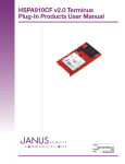
Terminus T3
Products User Manual
Bulletin
Revision
Date
JA19-UM
A00
01 July 2015
TABLE OF CONTENTS
TABLE OF CONTENTS and DISCLAIMER............................................................................................................................... 2
T3 General Description............................................................................................................................................................ 3
Block Diagram......................................................................................................................................................................... 3
T3 Overview............................................................................................................................................................................. 3
T3 Connections..................................................................................................................................................................... 3-5
Terminals
RS232
USB
LED Indicators
Antenna Connections
SIM Card
T3 Electrical Specifications................................................................................................................................................... 6-8
Absolute Maximum Ratings
Recommended Operating Conditions
Cellular Antenna Specifications
GPS Antenna Specifications
Mechanical Specifications....................................................................................................................................................... 9
Getting started with T3 Terminus Applications................................................................................................................. 10-13
Starting a Terminal Session
Sending an SMS
Making a GPRS Data Call
GPS
Ordering Information.............................................................................................................................................................. 14
Revision History..................................................................................................................................................................... 14
DISCLAIMER
The information contained in this document is the proprietary information of Connor-Winfield Corporation and its affiliates (Janus Remote Communication). The contents are confidential and any disclosure to
persons other than the officers, employees, agents or subcontractors of the owner or licensee of this document, without the prior written consent of Connor-Winfield, is strictly prohibited. Connor-Winfield
makes every effort to ensure the quality of the information it makes available. Notwithstanding the foregoing, Connor-Winfield does not make any warranty as to the information contained herein, and does
not accept any liability for any injury, loss or damage of any kind incurred by use of or reliance upon the information. Connor-Winfield disclaims any and all responsibility for the application of the devices
characterized in this document, and notes that the application of the device must comply with the safety standards of the applicable country, and where applicable, with the relevant wiring rules. ConnorWinfield reserves the right to make modifications, additions and deletions to this document due to typographical errors, inaccurate information, or improvements to programs and/or equipment at any time and
without notice. Such changes will, nevertheless be incorporated into new editions of this application note.
All rights reserved 2011 Connor-Winfield Corporation
Terminus T3 User Guide JA19-UM
Page 2
Rev: A00
Date: 07/01/15
© Copyright 2015 Janus Remote Communications Specifications subject to change without notice
All Rights Reserved See website for latest revision.
Not intended for life support applications.
T3 Terminus Description
The Terminus T3 is a communication control terminal with a compact, rugged enclosure that encapsulates everything
needed for easy M2M integration. The multiple orderable versions allow for system deployment in different networks
with little to no change in the design investment.
Powered by the Terminus Common Footprint devices, the T3 contains all circuitry required to give your application
access to GSM, HSPA, EVDO, even LTE based network technology. It can receive power from a 5v source, contains
two communication interfaces, and an easy to use input to control ON/OFF remotely. Additionally, Janus offers
Python examples for the modems equipped with the interpreter to add scripting capabilities to your application.
T3 Connections
Terminals
The 4 position terminal section serves as the power supply input. It is also the access point for the external disable
input. Janus carries mating connectors for the terminal block, but the part number is referenced for the user if they
need to find something we do not carry.
Pin
Description
1
2
3 4 External Disable
Ground
Ground
5V Supply
Terminal Part Number: OSTOQ041251
Figure 1: T3 Terminal Block Diagram
External Disable
This input signal is designed to put the unit into the lowest possible power state without needing to cut power
entirely. It can be used by simply grounding the signal, then released when not needed.
This signal is internally pulled up to 5v. It should only be controlled via grounding or floating.
Terminus T3 User Guide JA19-UM
Page 3
Rev: A00
Date: 07/01/15
© Copyright 2015 Janus Remote Communications Specifications subject to change without notice
All Rights Reserved See website for latest revision.
Not intended for life support applications.
T3 Connections continued
RS232
The DB9 port follows the standard for RS-232 communications and gives the connections for serial interaction with
hardware handshaking.
Pin
Description
Direction
1 2
3
4 5
6 7
8
9 DCD
RXD
TXD
DTR
GND
DSR
RTS
CTS
RING
Output
Output
Input
Input
Supply
Output
Input
Output
Output
USB
The USB B type port is directly connected to the modem, giving several interfaces in one connection for application
ease. This port can be used for various functions, including firmware updates of the modem. This port does not
provide power to the T3, which must come from the main terminal input.
LED Indicators
The T3 contains two LEDs for feedback to the user.
Status – Green LED
This LED is T3 feedback on readiness of the modem to accept commands, and is automatically controlled
internally. When the unit is available for communications this will be illuminated. When the modem is not ready,
either through external disable control or the use of low power AT+CFUN modes this LED will be turned off.
Logically, it is tied to the CTS (clear to send) signal.
Cellular – Amber LED
This LED is directly connected to the modem’s cellular status signal. It can be user controlled through AT
commands, or set to automatic control by the modem for cellular status feedback.
Please consult the modem AT command guide for control commands. AT#GPIO and AT#SLED are the common
commands.
Description of status:
LED Status Permanently Off Permanently On
Slow Blinking (0.3 sec on / 2.7 sec off) Fast Blinking (0.5 sec on / 0.5 sec off) Device Status
Cellular radio is off
On/Searching
Registered
Shutting down
Terminus T3 User Guide JA19-UM
Page 4
Rev: A00
Date: 07/01/15
© Copyright 2015 Janus Remote Communications Specifications subject to change without notice
All Rights Reserved See website for latest revision.
Not intended for life support applications.
T3 Connections continued
Antenna Connections
These are bulkhead antenna connections for wireless communication to cellular and GPS technology.
SMA
Cellular and RX Diversity antenna connections
Pin
Description
Center Pin
Shield
Signal
Ground
MCX
GPS antenna connection
Pin
Description
Center Pin
Shield
Signal
Ground
SIM Card
The SIM card port is located inside of the T3, on the module itself.
To insert a SIM card, please follow these instructions.
Step 1.
To access the SIM card holder, remove the four TX-10 screws from the ruggedized aluminum enclosure.
These screws are located on the panel of the T3 that includes the RS232 DB9 and RF connections.
Step 2. Slide out the panel which will include the T3 board.
Step 3. Locate the SIM card holder on top of the Terminus Plug-In board.
Step 4. Slide the top of the SIM card holder back to unlock, insert the SIM card and close. Slide back to the original
position to lock back in place.
Step 5. Slide the panel back into the enclosure, replace, and tighten the four TX-10 screws.
Terminus T3 User Guide JA19-UM
Page 5
Rev: A00
Date: 07/01/15
© Copyright 2015 Janus Remote Communications Specifications subject to change without notice
All Rights Reserved See website for latest revision.
Not intended for life support applications.
Electrical Specifications:
Absolute Maximum Ratings:
Parameter
Minimum
Nominal
Maximum
Unit
Note
Storage Temperature
Supply (Supply & Enable Input)
VIN (RS-232 Inputs)
-40
0
-25
-
-
-
85
6
25
°C
Volt
Volt
1
1,2
1
Notes:
1) Operation of the device at these or any other conditions beyond those listed under Recommended Operating Conditions is not implied. Exposure to Absolute Maximum Rating conditions for extended periods of time may affect device reliability.
2) The supply inputs are protected from transients beyond the Recommended Operating Conditions. If transients persist the supply will be latched in a disable state until the input is lowered.
Recommended Operating Conditions:
Parameter
Minimum
Nominal
Maximum
Unit
Note
Operational Temperature:
Supply Peak Supply Current
-40
4.75
1.5
25
5.0
-
80
5.25
-
°C
Volt
Amp
1
Mode
Type
Terminal Disabled
-
Average (mA)
Description
.140External Disable Grounded, modem off.
Using: RS-232
AT+CFUN=1
WCDMA
34
Idle, no call in progress. Full functionality of
GSM
-
the module
AT+CFUN=4
WCDMA
33
Disabled TX and RX; module is not registered
GSM
-
on the network
AT+CFUN=5
WCDMA
10Full functionality with power saving; Module registered
GSM
-
on the network can receive incoming call sand SMS
AT+CFUN=0
WCDMA
10Minimum functionality. In this mode the AT interface GSM
-
is not accessible. Must be woken up externally by
SMS or Socket attempt.
Using: USB
AT+CFUN=1
AT+CFUN=4
AT+CFUN=0
WCDMA
38
GSM
-
WCDMA
37
GSM
-
WCDMA
5
GSM-
Idle, no call in progress.
Full functionality of the module.
Disabled TX and RX; module is not registered on the
network
Full functionality with power saving; Module registered
on the network can receive incoming call sand SMS
Using: RS-232 & USB
AT+CFUN=1
WCDMA
51Idle, no call in progress. Full functionality of
GSM
-
the module.
AT+CFUN=4
WCDMA
51Disabled TX and RX; module is not registered on the
GSM
-
network
AT+CFUN=5
WCDMA
11
Full functionality with power saving; Module registered
GSM
-
on the network can receive incoming call sand SMS
AT+CFUN=0
WCDMA
10
Minimum functionality. In this mode the AT interface
GSM
-
is not accessible. Must be woken up externally by
SMS or Socket attempt.
Notes:
1)Peak Supply Current specification is stated as the minimum amount of current the external power supply must be able to supply during the TX burst
of the embedded cellular radio. Please refer to the Plug-In User Manual for power supply characteristics of the embedded Plug-In Module in the
Terminus T3. Plug-In User Manual can be downloaded at http://www.janus-rc.com/terminuscf.html
2)Average Supply Current specification is stated as the maximum average current the Terminus T3 terminal can draw while maintaining junction temperatures within the internal power supply IC’s specifications. It is the applications responsibility to maintain operation within this limit to maintain
reliable operation over the life of this terminal product.
3)Values taken with GPS turned OFF. When GPS is used, expect a 20mA increase during operating states.
Terminus T3 User Guide JA19-UM
Page 6
Rev: A00
Date: 07/01/15
© Copyright 2015 Janus Remote Communications Specifications subject to change without notice
All Rights Reserved See website for latest revision.
Not intended for life support applications.
Electrical Specifications continued
Cellular Antenna Specifications:
Parameter
HSPA910T3
Description
Frequency Range
Bandwidth
Gain
Impedance
Input Power
VSWR Absolute Max
VSWR Recommended
Depending on frequency bands provided by the network operator, the customer
should use the most suitable antenna for those frequencies.
70MHz in GSM850
80 MHz in GSM900
170 MHz in DCS & 140 MHz PCS
70 MHz in WCDMA850
80 MhHz in WCDMA900
460 MHz in WCDMA1700
140 MHz in WCDMA1900
250 MHz in WCDMA2100
Gain < 3dBi
50W
>33 dBm (2W) peak power in GSM
>24 dBm Average power in WCDMA
≤ 5:1
≤ 5:1
EVDO910T3
Frequency Range
Bandwidth
Gain
Impedance
Input Power
VSWR Absolute Max
VSWR Recommended
Depending on frequency bands provided by the network operator, the customer
should use the most suitable antenna for those frequencies.
70MHz in CDMA BC0
140 MHz in CDMA BC
Gain < 5dBi
50W
> 24.4 dBm in CDMA
≤ 5:1
≤ 2:1
CDMA910T3
Frequency Range
Bandwidth
Gain
Impedance
Input Power
VSWR Absolute Max
VSWR Recommended
Depending on frequency bands provided by the network operator, the customer
should use the most suitable antenna for those frequencies.
70MHz in CDMA BC0
140 MHz in CDMA BC
Gain < 5dBi
50W
> 24.4 dBm in CDMA
≤ 5:1
≤ 2:1
Terminus T3 User Guide JA19-UM
Page 7
Rev: A00
Date: 07/01/15
© Copyright 2015 Janus Remote Communications Specifications subject to change without notice
All Rights Reserved See website for latest revision.
Not intended for life support applications.
Electrical Specifications continued
Cellular Antenna Specifications:
LTE910T3 – AT&T
Frequency Range
Bandwidth
Gain
Impedance
Input Power
VSWR Absolute Max
VSWR Recommended
Depending on frequency bands provided by the network operator, the customer
should use the most suitable antenna for those frequencies.
GSM850: 70Mhz
GSM1900 (PCS): 140Mhz
WCDMA 1900 (B2): 140Mhz
WCDMA 850 (B5): 70Mhz
LTE 1900 (B2): 140Mhz
LTE 1700 (B4): 445Mhz
LTE 850 (B5): 70Mhz
LTE 700 (B17): 42Mhz
Gain < 3dBi
50Ω
>33 dBm (2W) peak power in GSM
>24 dBm Average power in WCDMA & LTE
≤ 10:1
≤ 2:1
LTE910T3 – Verizon
Frequency Range
Bandwidth
Gain
Impedance
Input Power
VSWR Absolute Max
VSWR Recommended
Depending on frequency bands provided by the network operator, the customer
should use the most suitable antenna for those frequencies.
LTE 1700 (B4): 445Mhz
LTE 700 (B13): 41Mhz
Gain < 3dBi
50Ω
>24 dBm Average power
≤ 10:1
≤ 2:1
GPS Antenna Specifications:
Parameter
GPS Enabled Units
Description
Input Voltage Range
Frequency Range
Gain
Impedance
VSWR
Current Consumption
2.85V
1575.42± 2 MHz
=< 15dB overall at the connector (Antenna and LNA included)
50Ω
TBD
30mA Max, 20mA Typ
Terminus T3 User Guide JA19-UM
Page 8
Rev: A00
Date: 07/01/15
© Copyright 2015 Janus Remote Communications Specifications subject to change without notice
All Rights Reserved See website for latest revision.
Not intended for life support applications.
Mechanical Specifications:
.4491
.2250
2.3500
1.0625
.3250
5.2142
4.1142
1.811
0.790
All measurements in inches unless otherwise noted.
Terminus T3 User Guide JA19-UM
Page 9
Rev: A00
Date: 07/01/15
© Copyright 2015 Janus Remote Communications Specifications subject to change without notice
All Rights Reserved See website for latest revision.
Not intended for life support applications.
Getting started with the T3
This will take you through the basic steps required to power the Terminus T3 and communicate with the modem.
Please confirm that you have these items before continuing. If you are evaluating the GSM or HSPA based T3 ensure
that you have an active SIM card. If evaluating the CDMA or EVDO based T3 you will not have a SIM card, but will
need an account attached to your device’s MEID which can be found on the bottom of the T3. You can evaluate the
basic functions without these steps, but in order to fully evaluate cellular connectivity it is required.
• Power Supply with the terminal block mating connection
• RS232 DB9 ended cable or USB B to A cable
• SMA Cellular Antenna
Starting a Terminal Session
Step 1
• Attach the cellular antenna to the SMA bulkhead connector.
• If applicable, insert the SIM card to the modem’s SIM holder.
• Connect the RS232 cable or USB cable to the DB9 or USB connection, respectively.
Step 2
Apply power to the T3 via the terminal blocks. The T3 will begin booting the modem, and you will see the amber
LED illuminate. In a few moments the green LED should illuminate, indicating the modem is ready to accept
commands.
Step 3 – Using RS232
Open HyperTerminal or an equivalent terminal emulator and start a new session. Use the following settings as
they are the default for T3 communications.
Bits per second: 115200
Data Bits: 8
Parity: None
Stop Bits: 1
Flow control: Hardware
Step 3 – Using USB
If this is the first time using this modem type on your PC, you should see several virtual COM ports appear in the
device manager. You will want to download the USB drivers for your modem type, which can be found on the
Janus-RC website.
Once the drivers are installed and the ports are available, you can open a terminal session with the following
settings as they are the default for T3 communications.
Bits per second: 115200
Data Bits: 8
Parity: None
Stop Bits: 1
Flow control: None
Terminus T3 User Guide JA19-UM
Page 10
Rev: A00
Date: 07/01/15
© Copyright 2015 Janus Remote Communications Specifications subject to change without notice
All Rights Reserved See website for latest revision.
Not intended for life support applications.
Getting started with the T3 continued
Starting a Terminal Session continued
Step 4
Click on the “Call” button in HyperTerminal to make the connection. In the window you should now be able to
send AT commands. To make sure you have a proper connection, type “AT” into the window (without quotes), and
press Enter. You should receive a response of “OK”.
If you do not receive that response, go back and check to make sure you’ve selected the correct COM port, as
well as the settings.
Step 5
The next thing is to set the modem for proper operation and wait for registration. Although the modems are
factory set by default to work in a wide range, ensuring these are set is still a good idea.
GSM and HSPA
For T-Mobile & MVNO
• AT#SELINT=2 – This makes use of the most recent AT command set
• AT#ENS=1 – Ensures some automatic settings used
CDMA and EVDO
These units require some extra steps that are thoroughly detailed in our Provisioning App Note found here:
http://www.janus-rc.com/Documentation/JA01-AN111_Provisioning-CDMA.pdf
Step 6
Check the network status by entering “AT+CREG?” without the quotations and press ENTER.
The response will be +CREG: 0,1 or +CREG: 0,5 meaning the device is registered to the home network or
roaming, respectively. If the response is different than this please refer to the AT Command guide as well as verify
the account is active.
Step 7
Check the signal quality by entering “AT+CSQ” without the quotations and press ENTER.
The response will be +CSQ: <rssi>,<ber>
<rssi> Signal Strength
99
Not known or detectable
0-31 dBm = (rssi*2) – 113
Example: A result of 31 indicates -51dBm or greater.
An rssi value of >=10 in typical applications if fine and you will usually see about 12-20 in normal to good signal,
but note that worst case it can be lower but still register and perform normal functions.
Sending an SMS
SMS (Select Message Service) mode allows you to send a text message (max 160 characters) to an SMS capable
subscriber unit.
• Set the SMS mode to text. This must be entered every power cycle.
AT+CMGF=1<cr>
• To enter the receiving subscriber unit phone number and message enter:
AT+CMGS=”8885551234”
Wait for response”>” then enter message text
Enter “ctrl z” <cr> to end the message
Terminus T3 User Guide JA19-UM
Page 11
Rev: A00
Date: 07/01/15
© Copyright 2015 Janus Remote Communications Specifications subject to change without notice
All Rights Reserved See website for latest revision.
Not intended for life support applications.
Getting started with the T3 continued
Making a GPRS data call (socket dial)
GPRS is a data service that uses Packet Data Protocol (PDP).
• Set up the PDP context parameters
Enter AT+CGDCONT=1, “IP”, “APN”, “0.0.0.0”,0,0<cr>
Where APN is specific to the service provider being used.
• Activate the PDP context
Enter AT#SGACT=1,1,”v”, “p”
Where v is your user ID and p is your password.
If there are none required for your account you can leave them blank.
• Open the socket connection
Enter AT#SD=1,0,IPP,IPA,0,0,0
Look for response “CONNECT”. This opens a remote connection via socket
IPP = the remote host port of the server you are trying to connect to. (0 to 65535)
IPA = the IP address of the server hyou are trying to connect to in the format:
“xxx.xxx.xxx.xxx”
• At this point a data session is active and data can be sent from the Terminus to the remote device and visa versa.
• To exit the data session and return to command mode, send the characters”+++” and wait for the OK response
• Enter AT#SH=1 to close the socket
GPS
HSPA910T3
The data can be acquired in two methods.
Method 1:
• Send command AT$GPSP=1<cr>
• Send command AT$GPSACP<cr>
$GPSACP can retrieve GPS data at any point when $GPSP=1
Method 2:
• Configure Unsolicited NMEA Data:
• Send command to enable NMEA stream
AT$GPSNMUN=<enable><gga><gll><gsa><gsv><rmc><vtg><cr>
Select parameter “1” to enable or “0” to disable for your NMEA stream requirements
EXAMPLE: AT$GPSNMUN=1,1,1,1,1,1,1
• Start NMEA Stream:
Send command AT$GPSP=1<cr>
• End NMEA Stream:
Send command AT$GPSP=0<cr>
Terminus T3 User Guide JA19-UM
Page 12
Rev: A00
Date: 07/01/15
© Copyright 2015 Janus Remote Communications Specifications subject to change without notice
All Rights Reserved See website for latest revision.
Not intended for life support applications.
Getting started with the T3 continued
GPS continued
EVDO910T3
The data can be acquired in two methods.
Method 1:
• Send command AT$GPSP=1<cr>
• Send command AT$GPSACP<cr>
$GPSACP can retrieve GPS data at any point when $GPSP=1
Method 2:
• Configure Unsolicited NMEA Data:
• Send command to enable NMEA stream
AT$GPSNMUN=<enable><gga><gll><gsa><gsv><rmc><vtg><cr>
Select parameter “3” to enable or “0” to disable for your NMEA stream requirements
EXAMPLE: AT$GPSNMUN=3,1,1,1,1,1,1
• Start NMEA Stream:
Send command AT$GPSP=1<cr>
• End NMEA Stream:
Send command AT$GPSP=0<cr>
Terminus T3 User Guide JA19-UM
Page 13
Rev: A00
Date: 07/01/15
© Copyright 2015 Janus Remote Communications Specifications subject to change without notice
All Rights Reserved See website for latest revision.
Not intended for life support applications.
Terminus T3
Products User Manual
Terminus Models & Ordering
Ordering
Description
HSPA910T3 v1.0
EVDO910T3 v3.0
CDMA910T3 v2.0
CDMA910T3 v3.0
CDMA910T3 v4.0
LTE910T3 v1.0
LTE910T3 v2.0
LTE910T3 v3.0
HSPA+/UMTS/EDGE/GPRS/GSM
(AT&T Certified)
EV-DO (Verizon)
CDMA-1xRTT (Sprint)
CDMA-1xRTT (Verizon)
CDMA-1xRTT (Aeris)
LTE (AT&T)
LTE (Sprint)
LTE (Verizon)
Revision History
Revision Revision Date
Note
A00
A01
Advanced Release - User Manual
Terminal Block update and Mechanical Dimensions update
07/01/15
07/23/15
Division of The Connor-Winfield Corporation
2111 Comprehensive Drive • Aurora, Illinois 60505
630.499.2121 • Fax: 630.851.5040
www.janus-rc.com