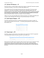
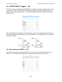
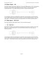
1
TVI I300 Hardware Manual
© Essential Viewing Systems Limited 2010
Essential Viewing
TVI I300 Hardware Manual
Page 1
TVI I300 Hardware Manual
© Essential Viewing Systems Limited 2010
1
OVERVIEW ......................................................................................................................................................... 3
2
SPECIFICATIONS.............................................................................................................................................. 4
3
MECHANICAL DIMENSIONS......................................................................................................................... 5
4
TVI I300 BOARD CONNECTORS.................................................................................................................... 6
5
6
4.1
CONNECTOR PARTS........................................................................................................................................ 7
4.2
CELLULAR RF ANTENNA – J9 ........................................................................................................................ 8
4.3
AUDIO INPUTS/OUTPUTS – J21....................................................................................................................... 8
4.4
POWER INPUT – J23........................................................................................................................................ 8
4.5
RS422/RS485 & TRIGGERS – J24 .................................................................................................................. 9
4.6
ASYNCHRONOUS RS232 – J25 ....................................................................................................................... 9
4.7
SYNCHRONOUS RS232 – J26........................................................................................................................ 10
4.8
ETHERNET – J27........................................................................................................................................... 10
4.9
STATUS LEDS – J31 & J32........................................................................................................................... 11
4.10
VIDEO OUTPUT – J34 ................................................................................................................................... 12
4.11
VIDEO INPUTS – J35 & J36........................................................................................................................... 12
4.12
EXTERNAL SIM – J38 .................................................................................................................................. 13
4.13
USB PORTS – J39......................................................................................................................................... 13
FACTORY CONFIGURATION ...................................................................................................................... 14
5.1
OEM DEFAULTS .......................................................................................................................................... 14
5.2
FACTORY RESET .......................................................................................................................................... 15
5.3
COMPLETE CONFIGURATION ERASE............................................................................................................. 15
SAFETY RECOMMENDATIONS .................................................................................................................. 17
Page 2
TVI I300 Hardware Manual
© Essential Viewing Systems Limited 2010
1 Overview
TVI I300
OEM CODEC Rev 2.0
WARNING - OBSERVE PRECAUTIONS
FOR HANDLING ELECTROSTASTIC
SENSITIVE DEVICES
To support OEM integration Essential Viewing provides two boards providing equivalent
functionality to the TVI C200 and TVI C300 encoders. This manual covers the TVI I300 which
has been designed to allow for the construction of a unit providing as a minimum the capabilities
of the TVI C300 encoder.
The I300 provides for the capture and compression of analogue video and audio to a digital
stream where this stream can be forwarded to a TVI Server for distribution to one or more
recipients. This stream is normally formed into IP packets for transport over any network
supporting IP. The I300 provides two routes for IP streaming, namely;
•
•
An Ethernet port for operation over a LAN or for connection to a router for operation
over a WAN,
An integrated cellular modem supporting streaming over GPRS, EDGE, WCDMA and
HSDPA networks.
The I300 has been designed for integration into an enclosure offering RF shielding and
operation as an open system may cause harmful interference to other electrical devices in
close proximity.
To meet EMC regulations it is imperative that the board is mounted in an enclosure that
provides RF shielding. All bulkhead connectors must be grounded to the enclosure and, where
stated in the documentation, shielded cables must be used to link the board to the bulkhead
connectors.
It is the responsibility of the integrator to obtain the necessary regulatory compliance to cover
operation of the unit within the territories into which the unit will be deployed.
Page 3
TVI I300 Hardware Manual
© Essential Viewing Systems Limited 2010
2 Specifications
Input supply voltage
9v to 36v DC
Power requirements @ nominal 12v DC
Sleep
Standby
Operational over LAN
Operation over WCDMA
Operation over GPRS
0.1W
1.7W
6.1W
8.3W
9.5W
Max power requirement (Low signal GPRS) 1A @ 12v, 12W
Operating temperature (free air)
-32oC to 80oC
Storage temperature
-32oC to 125oC
Dimensions (L x W)
127 x 145 mm
Video Inputs
2 x composite 1v p-p
Video Output
1 x composite 1v p-p
Audio Inputs
2 x line level (-10 dBv)
Audio Outputs
2 x line level (-10 dBv)
Ethernet Interface
10/100 Base-T
USB
Dual USB 2.0 Host
Cellular Modem
Telit UC864-G
Serial Ports
1 x RS232
1 x RS422/RS485
1 x Synchronous Serial (SSI)
Status
drives 5 x Tri-state LEDs
Page 4
TVI I300 Hardware Manual
© Essential Viewing Systems Limited 2010
3 Mechanical Dimensions
The TVI I300 PCB is 120mm long by 145mm wide by 1.6mm deep. The board incorporates six
M3 sized grounded holes to support mounting of the board within an enclosure. The mounting
points are specified by the following diagram where all dimensions are in mm and the view is of
the top side of the board.
Note that when using the mounting holes, an M3 flat washer must be used on both sides of the
board where the washer must have a diameter no greater than 7mm.
The I300 board includes a SIM carrier to support cellular operation where this is mounted at the
front of the board extending the length by 7mm to 127mm.
Page 5
TVI I300 Hardware Manual
© Essential Viewing Systems Limited 2010
4 TVI I300 Board Connectors
The I300 board has been designed for mounting within an enclosure where connectivity to either
a companion board or to bulkhead connectors is achieved via flying leads to board mount
headers. The following diagram illustrates the layout and location of the I300 headers and
connectors where these are prefixed by a “J” code on the PCB.
Note that headers utilised for only for manufacture are not documented and must remain
unconnected during normal operation.
Page 6
TVI I300 Hardware Manual
© Essential Viewing Systems Limited 2010
4.1 Connector Parts
The following parts are required for connection to the I300 board. Note that wires must not be
soldered directly to any pins on the board.
Part
50 ohm SMA plug
Quantity Port(s)
1
Cellular RF
Mini SMB 75ohm plug (RG-179 cable)
3
Amphenol: 903-586P-71A
2 x video in
1 x Video out
Tyco Electronics: 5415484-1
1
JST, PHR connector
Audio
PHR-5
(24 to 28 AWG cable)
3
JST, PHDR connector
Ethernet
PHDR-08VS
Status LEDs
(24 to 28 AWG cable)
Ext. SIM
5
JST, PHDR connector
USB 2.0
PHDR-10VS
RS232
(24 to 28 AWG cable)
RS422
SSI
Status LEDs
1
Molex
Power
43025-0200
(24 AWG cable)
JST – (Crimp connector for all parts
except power)
75
1 x PHR-5
3 x PHDR-08VS
SPHD-002T-P0.5
5 x PHDR-10VS
Molex – (Crimp for power)
43030-0007
Page 7
2
Power
TVI I300 Hardware Manual
© Essential Viewing Systems Limited 2010
4.2 Cellular RF Antenna – J9
The I300 includes an onboard cellular modem which requires an external RF antenna to operate.
The antenna connector on the I300 is an SMA socket labelled as J9.
The connection from J9 to the external antenna must be via coax with a 50 ohm per meter
impendence. If the link to the antenna is routed through a bulkhead connector then this
connector must be a 50 ohm coax RF connector where the body of the RF connector is grounded
to the enclosure. The internal linkage from J9 to the bulkhead connector must be 50 ohm coax
and a 50 ohm SMA plug must be used. It is vital that the connection between the coax cable
and the bulkhead connector maintain the integrity of the coax shielding.
Failure to use the correct coax cable and connectors will result in poor cellular performance and
is likely to cause undesirable EM interference and potentially damage to the modem.
4.3 Audio Inputs/Outputs – J21
The I300 provides dual channel line in audio and dual channel line out audio on header J21
where inputs and outputs are at line level. The following table specifies the mating connector
and connector pins.
J21 – 5x1 JST PHR connector
Description
Pin
Audio left input
1
Common ground
2
Audio left output
3
Audio right input
4
Audio right output
5
4.4 Power Input – J23
The I300 is powered via J23 where an input voltage in the range of 9v to 36v DC is supported.
The following table specifies the mating connector and connector pins.
J23 – 2x1 Molex Micro-Fit header 3.0mm pitch
Description
+DC supply
0v (chassis GND)
Pin
1
2
Note that while the I300 board incorporates a filter on the DC input it may be necessary in some
circumstances to utilise a common mode choke on the power input to suppress induced
electromagnetic interference and DC-DC switching noise. Where a choke is utilised within an
enclosure it is important to minimise the length of the cables between the DC input socket and
the choke.
Page 8
TVI I300 Hardware Manual
© Essential Viewing Systems Limited 2010
4.5 RS422/RS485 & Triggers – J24
The I300 provides a configurable RS422/RS485 port together with three isolated trigger inputs
on header J24. Each of the triggers is activated by applying an external voltage across the
trigger input and the trigger ground. The following table specifies the mating connector and
connector pins.
J24 – 5x2 JST PHD connector
Description
Pin
Tx GND
1
Tx +ve
2
Tx -ve
3
Rx GND
4
Rx +ve
5
Rx -ve
6
Trigger 1
7
Trigger GND
8
Trigger 2
9
Trigger 3
10
When using RS422 the impedance of the Rx and Tx pairs can be switched between 120 ohms
and high impedance via the jumpers J5 and J28 respectively. The impedance is 120 ohms with
the jumper inserted.
4.6 Asynchronous RS232 – J25
The I300 provides a fully connected RS232 port for asynchronous serial communications on
header J25. The following table specifies the mating connector and connector pins.
J25 – 5x2 JST PHD connector
Description
Pin
DCD
1
RxD
2
TxD
3
DTR
4
GND
5
DSR
6
RTS
7
CTS
8
RI
9
GND
10
Page 9
TVI I300 Hardware Manual
© Essential Viewing Systems Limited 2010
4.7 Synchronous RS232 – J26
The I300 provides an RS232 port for synchronous serial communications with devices generating
a clock signal via header J26. The following table specifies the mating connector and connector
pins.
J26 – 5x2 JST PHD connector
Description
Pin
TxD
1
RxD
2
RTS
3
CTS
4
DCD
5
CLOCK
6
DTR
7
GND
8
<not connected>
9
<not connected>
10
4.8 Ethernet – J27
The I300 provides a 10/100 Base-T Ethernet port for IP communications on header J27. The
following table specifies the mating connector and connector pins.
J24 – 4x2 JST PHDR connector
Description
Pin
Pair A +ve
1
Pair A -ve
2
Pair B +ve
3
Pair C +ve
4
Pair C -ve
5
Pair B -ve
6
Pair D +ve
7
Pair D -ve
8
It is recommended that where possible shielded CAT-5E cable is utilised for linking J27 to a
bulkhead RJ45 connector to ensure signal integrity and to avoid EM interference. Where this is
not possible or where linkage to a companion device is internal to an enclosure, twisted pairs
must be used for each of the four Ethernet pairs.
It is imperative that a shielded RJ45 connector be used where the connector is grounded to the
enclosure (chassis ground) to avoid electromagnetic interference.
Page 10
TVI I300 Hardware Manual
© Essential Viewing Systems Limited 2010
4.9 Status LEDs – J31 & J32
The operational status reporting of the I300 is provided via five common cathode tri-state LEDs
where each should nominally be capable of illuminating as red, green, or orange (red plus
green). The function of the LEDs is defined as follows where the function and states are
detailed in the user manual;
LED
LED
LED
LED
LED
1
2
3
4
5
Power
IP-Link
Server-Link
HSDPA/3G State
EDGE/GPRS State
The I300 provides two headers to power the five status LEDs via J31 and J32. The forward
voltage of the LEDs must be 2v @ 20mA. The following tables specify the mating connectors
and connector pins for J31 and J32.
J31 – 5x2 JST PHDR connector
Description
Pin
LED 4 Red anode
1
LED 4 Green anode
2
LED 3 Red anode
3
LED 3 Green anode
4
LED 2 Red anode
5
LED 2 Green anode
6
GND
7
GND
8
GND
9
GND
10
J32 – 4x2 JST PHDR connector
Description
Pin
LED 5 Red anode
1
LED 5 Green anode
2
LED 1 Red anode
3
LED 1 Green anode
4
Reserved (do not connect)
5
GND
6
GND
7
GND
8
Page 11
TVI I300 Hardware Manual
© Essential Viewing Systems Limited 2010
4.10 Video Output – J34
The I300 provides a single video output via a 75 ohm mini SMB connector on J34. Note that the
connection from the board to the bulkhead connector must be 75 ohm coax cable and it is
recommended that a 75 ohm BNC bulkhead connector is used as illustrated below.
It is important to follow the manufacturer’s instructions in the connection of the coax cable to
the mini SMB connector and to the BNC connector to avoid EM interference and/or noise in the
video signal. The bulkhead connector must be grounded to the enclosure (chassis ground).
4.11 Video Inputs – J35 & J36
The I300 provides two video inputs via two 75 ohm mini-SMB connectors.
•
•
J35 – video input 1
J36 – video input 2
Note that the connection from the board to the panel mount connector should be 75 ohm coax
cable and it is recommended that 75 ohm coax bulkhead connectors are used as per the
following illustration.
It is important to follow the manufacturer’s instructions in the connection of the coax cable to
the mini SMB connector and to the BNC connector to avoid EM interference and/or noise in the
video signal. The bulkhead connectors must be grounded to the enclosure (chassis ground).
Page 12
TVI I300 Hardware Manual
© Essential Viewing Systems Limited 2010
4.12 External SIM – J38
The I300 provides both a PCB mounted SIM carrier (J13) and a header supporting operation
with a bulkhead mounted SIM via J38. Note that only one SIM can be utilised. The following
table specifies the mating connector and connector pins.
J38 – 4x2 JST PHDR connector
Description
Pin
SIM Power (Vcc)
1
SIM Data I/O
2
SIM Reset
3
SIM Inserted
4
SIM Clock
5
N/C
6
Chassis GND
7
Power GND
8
4.13 USB Ports – J39
The I300 provides two USB Host ports on header J39. The following table specifies the mating
connector and connector pins.
J39 – 5x2 JST PHDR connector
Description
Pin
USB B 5v DC
1
USB C 5v DC
2
USB B Data -ve
3
USB C Data -ve
4
USB B Data +ve
5
USB C Data -ve
6
USB B 0v DC
7
USB C 0v DC
8
Chassis GND
9
Chassis GND
10
It is imperative that the USB connector be grounded to the enclosure (chassis ground) to avoid
electromagnetic interference.
Page 13
TVI I300 Hardware Manual
© Essential Viewing Systems Limited 2010
5 Factory Configuration
The standard mechanism for installing firmware and for configuring the operational mode of an
I300 is via a USB mass storage device.
The I300 uses non volatile memory to store firmware and configuration where the configuration
partition includes both factory settings and user definable settings. The I300 supports OEM
modification of the factory settings to allow for a degree of customisation to accommodate
product specific features and product naming.
On inserting a USB pen drive the I300 searches for one of several files which define the
subsequent operation to be carried out. It is imperative that the root of the pen drive contain
only the files appropriate for one operation. The following are relevant for OEM integration.
5.1 OEM Defaults
The I300 supports the modification of a subset of the factory default configuration to allow for
OEM customisation. These OEM defaults are retained when applying a factory reset. OEM
defaults are applied by creating a single text file in the root of the pen drive with the name;
.OEM_DEFAULTS
The file should contain one or more settings each of the form;
setting=value
Each setting must start on a new line within the file. Note that if the file is empty, then the OEM
defaults will be erased.
Supported settings are;
Setting
Function
vendor
The vendor field is exported from the I300 to the TVI Server where this string
is then provided to TVI Manager and as required to the Viewing Clients. This
string will be displayed to inform the user as to the type of device. For
example;
vendor=TVI I300
product
This would result in TVI Manager displaying the connected device as a “TVI
I300”.
The product field is used by the I300 board to determine the functionality and
behaviour. For example;
product=I300
This would be used by the firmware to establish the board type and to control
the application of user configuration settings.
Page 14
TVI I300 Hardware Manual
© Essential Viewing Systems Limited 2010
5.2 Factory Reset
It is possible to remove the configuration settings of an I300 and restore the unit back to the
‘original factory defaults’. This operation does not remove any OEM Defaults that have been
applied and so the I300 will retain any OEM Default settings applied. This operation is designed
to be used by an end-user who wishes to reset their I300.
A factory reset is achieved by creating a single file in the root of the pen drive with the name;
.FACTORY_RESET
The file can be zero length as the I300 performs the reset based on the presence of the file
rather than the file contents.
5.3 Complete Configuration Erase
The I300 supports a complete erase of all configuration settings including the OEM defaults to
return the I300 to a blank state which may be required for manufacture testing. This is
achieved by creating a single file in the root of the pen drive with the name;
.ERASE_CONFIG
The file can be zero length as the I300 performs the configuration erase based on the presence
of the file rather than the file contents.
Page 15
TVI I300 Hardware Manual
© Essential Viewing Systems Limited 2010
Cellular Operation
The choice of external antenna will depend on operational factors and on the frequency bands
used by the selected network. To support global operation an antenna must support the
following GSM / WCDMA frequency bands;
70 MHz in GSM850
80 MHz in GSM900
170 MHz in DCS & 140 MHz in PCS
70 MHz in WCDMA850
140 MHz in WCDMA1900
250 MHz in WCDMA2100
Where the network is known, the user should select the most suitable antenna based on the
frequency band(s) provided by that network operator.
An antenna must have the following characteristics to match the Telit UC864-G modem;
VSWR absolute max <= 10:1 recommended <= 2:1
Input power > 33dBm peak power in GSM
Input power > 24dBm average power in WCDMA
Impedance 50 ohm
Furthermore if the I300 is used in the US market and/or Canada market, it is the responsibility of
both the manufacturer of the product containing the I300 and the end user to ensure that the use
of the product complies with the FCC and/or IC approval requirements.
The system antenna(s) used for this product must be installed to provide a
separation distance of at least 20 cm from all the persons and must not be colocated or operate in conjunction with any other antenna or transmitter.
The system antenna(s) used for this product must not exceed 3 dBi for mobile
and fixed or mobile operating configurations.
Users and installers must be provided with antenna installation instructions
and transmitter operating conditions for satisfying RF exposure compliance.
The product manufacturers are advised to clarify any regulatory questions and to have their
complete product tested and approved for FCC compliance.
It is recommended that the I300 is powered down before a SIM is removed or inserted to avoid
any inconsistency in the network settings stored by the Telit UC864-G module which may result
in a failure to connect to the network.
Page 16
TVI I300 Hardware Manual
© Essential Viewing Systems Limited 2010
6 Safety Recommendations
The I300 board contains ESD (electrostatic discharge) sensitive devices.
Electrostatic charges readily accumulate on the human body and equipment where
discharge can occur without detection. Permanent damage may occur on devices
subjected to high energy discharges. Proper ESD precautions are recommended to
avoid performance degradation or loss of functionality. Store any unused I300
boards in anti-static packaging.
The I300 uses an integrated Telit UC864-G cellular modem. The use of the I300
may be dangerous and has to be avoided in the following areas:
•
•
Where it can interfere with other electronic devices in environments such as
hospitals, airports, aircrafts, etc.
Where there is risk of explosion such as gasoline stations, oil refineries, etc.
Antenna characteristics must match those specified in this document and care must
be taken during installation to avoid any interference with other electronic devices.
There must be a minimum separation between an antenna and the human body of
20 cm.
The I300 incorporates reverse voltage protection and surge protection against DC
voltages not exceeding 50v DC.
Additional protection is recommended when operating from non regulated or
vehicle power supplies.
It is recommended that an inline fuse be fitted when operating from a vehicle
supply.
The power GND input corresponds to the I300 chassis ground and external power
isolation must be used where there is a risk of accidental connection to mains level
voltages.
It is the responsibility of the final unit manufacturer to ensure that the use of the
I300 is allowed in the country where the unit is sold and that all necessary
certification for the unit is in place.
Do not disassemble the I300 or attempt repair. Any mark of tampering will
invalidate any warranty.
Page 17