1
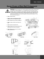
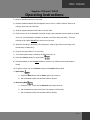
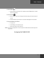
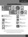
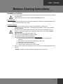
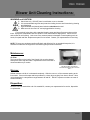
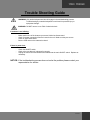
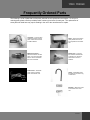
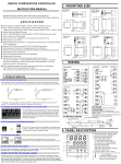
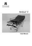
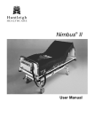
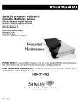
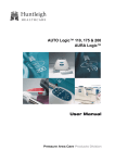
Sapphire Series 1100 and 1100 EC
Mattress Replacement System
Read Entire Manual before
Operating Device
OI-S1100600
Uncontrolled Document
Rev. 2.0 - 4/21/2008
User Instruction Manual
1100 / 1100 EC
Sapphire 1100 and 1100 EC
PLEASE NOTE: It is important that the user read the entire manual before operating this device.
USER ASSISTANCE INFORMATION:
If you have questions or need assistance with this product, call the company from whom it was
purchased, or contact Sunflower Medical L.L.C. at
1-888-321-3382
Table of Contents
Page
Symbol Definitions .................................................................. 3
General Warnings and Precautions ....................................... 4
Seven Zones of Bed Rail Entrapment.................................... 5
Device Information .................................................................. 6
Unpacking and Set-up............................................................. 7
Operating Instructions: ........................................................... 8
Keypad Quick Reference ...................................................... 10
Mattress Cleaning Instructions: ........................................... 11
Blower Unit Cleaning Instructions:...................................... 12
Trouble Shooting Guide........................................................ 13
Frequently Ordered Parts ..................................................... 14
Return/Exchange Goods Policy: .......................................... 15
Warranty Provisions: ............................................................ 15
Technical Description of the Equipment:
The two principle components of the Sunflower Medical Sapphire Series 1100 & 1100EC Mattress
System are a specialized air inflatable bladder (Air Mattress) and an electrically powered, Air
Blower/Control Unit.
2 of 16
1100 / 1100 EC
Symbol Definitions
Manual Definitions
Throughout this manual different type faces and icons are used to aid user readability and understanding
of the content. Below are some examples.
—
—
—
—
Standard Text
Bold Face Text
NOTE: or NOTICE
Bold and underlined
Used for regular information.
Emphasizes a word or phrase.
Sets apart special information or important instruction clarification.
Refers to special instances or where problems can occur.
This symbol highlights a WARNING or CAUTION
— A WARNING identifies situations or actions that may affect patient or user safety. Disregarding a
warning could result in patient or user injury.
— A CAUTION points out special procedures or precautions that personnel must follow to avoid
equipment damage.
This symbol highlights an ELECTRICAL SHOCK HAZARD WARNING
Symbols Found on Blower Unit
NOTE: Details about the control panel functions are located directly after the operation instructions on
page 10.
Manufacture’s Label
5A
250V
Replace fuse
as marked
This symbol marks the location
and specifications of the fuses.
This is a 5amp 250 volt in-line
fuse.
Manufacturer’s
Address
Environmental
Technology
Laboratory Logo
European CE
Marking
Manufacture
Date
Ratings
This symbol signifies that the
device is properly protected
from electrical shock.
Leakage
Test
Point
Sunflower
Medical Logo
Federal
Communications
Commission
Unit Grounding
Specifications
This symbol marks the
location of the leakage test
point screw.
3 of 16
1100 / 1100 EC
General Warnings and Precautions
WARNINGS
WARNING: DO NOT use this device if the power cord is cut, frayed or loosely
connected to the device.
WARNING: Electrically Powered Mechanism. Electrical Hazard may occur if
device is plugged into inadequate electrical outlet. To avoid electrical shock
hazard, make sure unit is plugged into a grounded A/C 110 Volt outlet.
WARNING: DO NOT remove cover. Refer servicing to qualified service
personnel. Disconnect power supply before servicing or cleaning.
WARNING: Be sure to secure mattress to the bed frame with the straps
provided. Failure to do so could result in personal injury or equipment damage.
CAUTIONS
CAUTION: Overheating may cause equipment damage or failure. Monitor the
unit to ensure that it functions in the proper operating temperature.
CAUTION: Keep out of direct sunlight.
CAUTION: DO NOT store unit in temperatures below 40° or greater than 95°
Fahrenheit (5° – 35° Celsius).
CAUTION: DO NOT expose to moisture or areas of extreme humidity.
CAUTION: Ensure that strap placement does not interfere with the operation of
the bed functions.
CAUTION: Medical Electrical Equipment needs special precautions regarding
EMC and needs to be installed and put into service according to the EMC
information provided in this manual. Portable and mobile RF communications
equipment can affect Medical Electrical Equipment. The use of Accessories,
transducers, and cables other than those specified by the manufacturer, may
result in increased emissions or decreased immunity of the equipment or system.
The equipment or system should not be used adjacent to or stacked with other
equipment and that if adjacent or stacked use is necessary, the equipment or
system should be observed to verify normal operation in the configuration in
which it will be used.
CAUTION: DO NOT use around an open flame.
4 of 16
1100 / 1100 EC
Seven Zones of Bed Rail Entrapment
WARNING: Bed rail entrapment is a serious health risk that can result in serious injury
or even death. Sunflower Medical L.L.C. recommends the use of bed rails if they are
available. Failure to use bed rails in raised position could lead to accidental patient falls.
Air mattresses have soft edges that may collapse when patients roll to that edge. When
using an Air Therapy system the caregiver is responsible for seeing that the mattress
properly fits the bed frame. It is also the caregiver’s ultimate decision whether or not to
use bed rails with the patient.
•
Zone 1: Within the Rail
•
Zone 2: Under the Rail, Between the Rail
Supports or Next to a Single Rail Support
•
Zone 3: Between the Rail and the Mattress
•
Zone 4: Under the Rail, at the Ends of the
Rail
•
Zone 5: Between Split Bed Rails
•
Zone 6: Between the End of the Rail and the
Side Edge of the Head or Foot Board
•
Zone 7: Between the Head or Foot Board
and the Mattress End
Zone One
Zone Two
Zone Four
Zone Six
Zone Three
Zone Five
Zone Seven
5 of 16
1100 / 1100 EC
Device Information
PURPOSE OF THE DEVICE
The purpose of the Sapphire Series 1100 & 1100EC Mattress System is to provide therapeutic benefit to
patients at risk or suffering from pressure ulcers.
The active component that has contact with the patient is a specialized, multi-cell air mattress sized to fit
a standard medical bed frame. The air mattress serves to replace the original mattress and is equipped
with 4 air hoses with connectors that mate with the Air Blower/Control Unit. The Control Unit is a self
contained, totally enclosed module that hangs by retractable hooks on the bed frame at the foot of the
bed or sits on the floor under the bed.
It is provided with a hospital grade electrical cord and a control panel that has selector switches and
indicator lights. The switches and indicators are protected under a flexible membrane to keep out liquid
spills and enhance clean-up and sanitation. Inside the Control Unit is a variable output blower, a valve
motor and air valves that allow the air mattress to operate in static mode or provide alternating pressure
variations within the mattress. There is also a printed circuit board, which provides the electrical controls.
The Control Unit has two user replaceable 250v 5.0 amp fuse near the AC Power Cord Entry.
Specifications
Standard Features
Feature
Therapeutic Features
Dimension
Feature
Dimension
Blower Unit Weight
11 lbs (4.98 kg)
Low Air Loss
Yes
Blower Unit Height
10.5” (26.67 cm)
Fowler Positioning
Yes
Blower Unit Width
16” (40.64 cm)
Alternation Therapy
Yes
Blower Unit Depth
6” (15.24 cm)
Electrical Characteristics
Feature
Rated Voltage
Rated Frequency
Rated Input Power
Fuse Rating
Power Failure Alarm
Patient Characteristics (for standard size)
Dimension
110 Volts
Feature
Max. Patient Height
60Hz
120 Volts
Max Patient Width
Dimension
78”
(198.12 cm)
26”
(66.04 cm)
250 Volts 5 Amp
Yes
6 of 16
1100 / 1100 EC
Unpacking and Set-up
Description of the Device:
The Sapphire Series 1100 & 1100EC Mattress Replacement System consists of a control unit, power
cord, a Low Air Loss Mattress and a waterproof, vapor permeable, easy-to-clean cover.
UNPACKING / PARTS BREAKDOWN:
Parts
-
-
Air Blower/Control Unit
Power Cord (Hospital Grade)
True Low Air Loss Mattress Replacement
Mattress Cover
Air Blower/Control Unit
and
True Low Air Loss Mattress with Cover
Tools Required: NONE
Unpacking instructions:
Remove the products from the packing material and examine for shipping damage. If damage is detected
in shipping, contact the freight company and file a damage complaint immediately.
Environmental Conditions:
CAUTION: Keep out of direct sunlight.
DO NOT expose to temperatures greater than 95 degrees or below 40 degrees Fahrenheit.
DO NOT expose to moisture or areas of extreme humidity.
Portable and mobile RF communications equipment can affect Medical Electrical Equipment. The use of
Accessories, transducers, and cables other than those specified by the manufacturer, may result in
increased emissions or decreased immunity of the equipment or system.
The equipment or system should not be used adjacent to or stacked with other equipment and that if
adjacent or stacked use is necessary, the equipment or system should be observed to verify normal
operation in the configuration in which it will be used.
NOTE: Some cellular telephones and similar devices transmit signals while they are ON, even when not
being used.
Directions for Mattress Placement:
Replace the existing bed mattress with True Low Air Loss Mattress. Secure Air Mattress to the bed frame
with straps provided.
Warning or Safety Instructions relating to setup:
WARNING: Make sure the power cord is plugged into a properly grounded A/C 110 Volt outlet.
7 of 16
1100 / 1100 EC
Sapphire 1100 and 1100 EC
Operating Instructions:
1) Remove standard mattress from the bed.
2) Replace standard mattress with the Sapphire Series 1100 or 1100EC mattress. (Be sure air
tubing is at the foot end of the bed.)
3) Strap air support mattress to bed frame on all four sides.
4) Place control unit on the footboard of the bed using the two retractable hooks located on the back
of the unit. (If no footboard is available, put blower on the floor away from traffic.) To avoid
blocking the air intake, DO NOT lay control unit on its back.
5) Attach the air tubing to the blower unit, being sure it snaps in tight. (Be sure air tubing is not
kinked and is unobstructed.)
6) Plug unit into grounded A/C 110 volt outlet.
7) Turn master power switch, located on the side of the unit, on.
8) Press the Autofirm button for quick inflation.
9) Placed the patient on the bed after inflation to insure the air cells do not become twisted or
kinked.
10) To get the control unit out of Autofirm mode, press Autofirm button again.
11) Static Mode
a. Press the Mode button until the Static option light comes on.
b. Set the desired comfort level with the Soft/Firm buttons
12) Alternating Mode
a. Press the Mode button until the Alternate option light comes on.
b. Set the desired cycle time with Cycle Time buttons (3-20 minutes)
c.
Set the desired comfort level with the Soft/Firm buttons.
8 of 16
1100 / 1100 EC
13) Fowler Feature
a. When elevating the head section of the mattress, press the Fowler button to increase
airflow for seat inflation.
14) Lock-out Feature
a. After 3 minutes, if there are no changes to the blower settings, the lockout feature will
activate.
b. Press and hold the Lock-out button for 5 seconds to disengage the lock-out feature.
15) For quick deflation or for CPR use:
a. Turn power off
b. Twist CPR plug on the mattress to open.
c.
Remove the hoses from the control unit.
Notice: The mattress is equipped with a 2-inch foam pad in the mattress base for patient support and
transportation.
For Inquires Call 1-888-321-3382
9 of 16
1100 / 1100 EC
Keypad Quick Reference
Lockout –
Locks all functions automatically after 3 mins. To
disable, press and hold lockout
button for 3 sec.
Alarm Silence Mutes the audible alarm.
(Visual light will not turn off
until failure is resolved.)
Firm –
Increases airflow for a firmer
setting.
Soft
Decreases airflow for a softer
setting.
Autofirm –
Quickly inflates mattress to
maximum firmness.
Fowler –
Used when head section of
bed is elevated. Increases
airflow to the mattress.
Cycle TimeIncreases or decrease the time
of cycle between 3 to 20
minutes.
ModePress the MODE button to
switch between Alternate and
Static Modes.
Refer to this page as needed for quick reference to the control panel functions.
Shows control panel layout for the blower unit and optional percussion attachment.
Provides individual button illustration and function description.
10 of 16
1100 / 1100 EC
Mattress Cleaning Instructions:
WARNING and CAUTION:
A. It is recommended that gloves and protective clothing be worn at all times during cleaning
and disinfecting
B. Hypercarbonate and phenol based solutions should not be used.
During Operation:
For normal soil, wipe down cover and interior sacs with a standard cleaning disinfectant and
wipe off excess moisture with a towel.
Laundering Mattress:
1. Disconnect the power from the Control Unit and deflate the interior sacs.
2. Disassemble cover, interior sacs, connecting hoses, and base. Place them in different
laundering baskets.
3. The interior sacs must be hand cleaned only. DO NOT place in sterilization room or
chamber. Use a spray disinfectant to wipe down interior sacs. Air-dry sacs. DO NOT
expose to heat.
4. Spray disinfectants and wipe down foam cover.
5. Place cover and base ONLY in washing machine.
6. Use standard hospital disinfectant/detergent.
7. Set washing cycles as recommended below: Regular Cycle
a) Pre-soak with disinfectant/detergent with diluted bleach in cold water (10
minutes.)
b) Main wash for 15 minutes (Time depending on soil level).
c) Rinse Cycle: 5 minutes minimum.
d) Spin/Drain Cycle: 5 minutes minimum.
e) Air-dry or place in dryer at very low or no heat.
8. After the cover, interior sacs, and base are dry, store them in a sterilized bag and seal for
next use.
NOTICE: DO NOT use water temperatures greater than 150°F (65°C).
11 of 16
1100 / 1100 EC
Blower Unit Cleaning Instructions:
WARNING and CAUTION:
A. Hand clean only. DO NOT place in sterilization room or chamber.
B. It is recommended that gloves and protective clothing be worn at all times during cleaning
and disinfecting
C. Hypercarbonate and phenol based solutions should not be used.
D. Make sure unit is turned “off” and unplugged before cleaning.
For normal soil, wipe down with a standard cleaning spray and wipe off excess moisture with a
towel. Spray with a disinfectant and let it stand for a few minutes before wiping down. Check corners
and creases for soil build-up. Look to see if any external parts are damaged or need replacing such as:
hooks, foot pads and filter. Replacement parts can be issued. Contact your representative for servicing.
NOTE: To keep your equipment working efficiently and effectively for an extended time period, it is
essential to make sure the equipment is cleaned regularly and well maintained.
Maintenance:
Air Filter
The foam air filter on the back of the Control Unit must be cleaned
weekly with warm soap and water. Replacement of the foam filter is
recommended every 6 months.
Storage:
The filter is easily removed and
reinserted through the gap in the back
case.
Deflate mattress until all air is exhausted completely. With the cover on, roll the mattress starting at the
foot section. Secure with straps and keep mattress in a clean dry area away from heat or flames. Store
unit and mattress in a temperature range between 40°and 95°. DO NOT expose to moisture or areas of
extreme humidity.
Disposition:
Once the unit has reached the end of its useable life, contact your representative for service, disposition
or replacement.
12 of 16
1100 / 1100 EC
Trouble Shooting Guide
WARNING: Only authorized personnel should engage in the troubleshooting process.
Troubleshooting by unauthorized persons could result in personal injury or
equipment damage.
WARNING: DO NOT remove cover. Risk of electrical shock.
If mattress is not inflating:
-
Make certain none of the hoses are punctured, kinked or disconnected.
Check for proper connections from the hoses to the unit. Make sure they are secure.
Check or clean intake filters.
Be sure CPR valve on the mattress is closed.
If there is power loss:
-
Check the ON/OFF switch.
Check to be sure that unit is plugged in correctly.
Unplug the Control Unit and check fuses located near the main ON/OFF switch. Replace as
necessary.
NOTICE: If the troubleshooting process does not solve the problem please contact your
representative for service.
13 of 16
1100 / 1100 EC
Frequently Ordered Parts
The following is a list of parts that are frequently ordered for self replacement and repairs. To aid you in
ordering parts, please use the provided product numbers given below for each part. The replacement of
some parts not listed here may require sending in the unit to the manufacturer for repairs.
Connector – Connects from
mattress to blower unit side
panel. Allows air movement
to inflate mattress.
Male CPC (Chrome) –
Attached to blower unit side
panel. Connects to Female
CPC to remove exhaust air
from unit to mattress.
Power Cords – Grounded
power cord for providing
power to the blower unit.
Filters – Removes dust and
other particles from the air
as it is pulled into the blower
unit.
Female CPC – Connects
from mattress to Male CPC
on blower unit. Removes
exhaust air from unit to
mattress.
Hooks – Collapsible hooks
that allow the unit to be hung
on bed frame.
Product #
96055
Brackets – Attach the hooks
to the bottom case of the
unit.
14 of 16
1100 / 1100 EC
Return/Exchange Goods Policy:
Return of Goods: 18% Return Charge for a Restocking Fee for returned goods when customer makes a
wrong order of items, still in original Packing. A Return Authorization Number (RAN) Form(s) will need to
be filled out and processed through the Sunflower Medical LLC Customer Service Department. Once
RAN is issued, customer must return all items placed on the RAN within five working days from the date
of the RAN to Sunflower Medical LLC. Without an Authorized RAN, all items will be returned to the
customer at the customer’s expense.
Repairs or Replacements are offered for defective items. Also a RAN action must be completed before
any repairs or replacements can be completed.
Sunflower Medical LLC: Replacement for wrong Items shipped, RAN form must also be completed, and
then items will be replaced or repaired at no cost.
Warranty Provisions:
Warranty: Sunflower Medical LLC; Warrants that all products provided under this agreement are free from
defects in material and workmanship, for the following stated warranty period from the date of delivery.
Sunflower Medical LLC guarantees all purchased equipment to be free from defects in material and
workmanship as follows: Control Unit – One (1) year; Mattress – Two (2) years on air cell welds; One (1)
year on Bottom Cover, Manifold & Foam Base; Top Cover – Ninety (90) Days. All parts found defective
within that period shall be repaired and/or replace, with the cost of repair and/or replacement, to be borne
by Sunflower Medical LLC. The warranty is not valid and repairs and/or replacement will not be made free
of charge, if the product has been misused or damaged by accident.
Sunflower Medical LLC reserves the right to make this determination based upon the condition of product
upon time of receipt.
Take our customer satisfaction survey and tell us what you think of our product!
Go to our Contact page at www.sunflowermedical.com
15 of 16
1100 / 1100 EC
Sunflower Medical L.L.C.
Customer Service Department
206 Jefferson St
P.O. Box 276
Ellis, Kansas 67637
Phone: 1-888-321-3381
www.sunflowermedical.com
Sunflower Medical L.L.C. is a registered trademark of Raye’s Inc. All specifications, equipment and prices
are subject to change without notice. Photos and drawings are representative of the products and may
vary slightly from actual production models. Contact or consult with your dealer to ensure proper
equipment sizes, specifications and options. Your local distributor is responsible for manual translation
for international use.
16 of 16