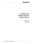
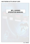
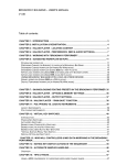
1
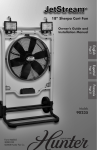
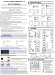
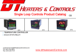
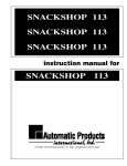
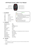
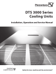
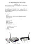
DTC Series Microprocessor Controller
4:Alarm options
1:
2:
3:
USER MANUAL
Carefully read all the instructions in this manual. Please place
this manual in a convenient location for easy reference.
5:Input 2(Remote SV or Position Feedback)
N:
A:
B:
C:
D:
E:
F:
G:
R:
General Notes
● DTC series instrument: 4 big LED display, 0-100%LED bar display output , Accuracy:
(Max±0.2% fus or ±1)≤±1 digit
Maximum resolution is 0.1 degree for RTD and TC input and 0.001 for analog input.
Auto/Manual control bumpless transfer features.
Dual output(heating+cooling), each channel with PID features
● Pleases make sure that the power cords and output types are manipulated correctly
Do check the wiring diagram stickers on the side of controller housing
96 :
85~265VAC
24DC : 24VDC
7:Communication
N: Without communication
K: RS-485
these two modes
● Out1 of controller was set as heating output, Out2 set as cooling output as factory
fault, operator can change it other way around if necessary, please refer to parameter
Oud in 6.3 parameter level 3
8:Re-Transmission
N : Without PV or SV re-transmission
P42 : PV re-transmission 4-20mA
P005 : PV re-transmission 0-5VDC
P010 : PV re-transmission 0-10VDC
● Controller with dual output features, cooling+heating outputs, refer to section 10 of this
manual, heating+cooling control
● Control set as PID with auto-tuning function as factory default
● ON/OFF Control: Set P=0.0,it will be changed as on/off control. Check
manual"6.1 parameter P " and "9.cotrol action instruction". Position
Without second inputs
4-20mA
0-20mA
0-10mA
0-5VDC
0-10VDC
1-5VDC
2-10VDC
Resistance feedback signal from valve
6:Power supply
● End user can set TC, RTD input signals freely by front panel, analog signals except
0-20mV and 0-50nmA need to be specificed before order
● Controller available with auto and manual control mode, and user can bumpless switch
1 alarm
2 alarms
3 alarms
S42 : SV re-transmission 4-20mA
S005 : SV re-transmission 0-5VDC
S010 : SV re-transmission 0-10VDC
2. Mounting and Dimensions
difference is HYS. when heating :PV>SV, OUT stop, when PV<SV-HYS,
1
90.0
104.0
44.0
58.0
50
● When anolog signal output, can using output buffer function when in some
special control position, which can make output more stable.
Check manual"6.2 level 2 bUFF parameter, and 6.3 level 3 bEr parameter"
14.6
14.6
Check manaual “9. Control mode ”“10. Heating/Cooling”
● when PID Control, we suggest adopt the Autotuning to improve the control
effect. Check"8.Autotuning"
(U
ni
t
:
mm)
50
50
44.0
MTC49
MTC94
MTC48
(U
ni
t
:
mm)
96
PV<SV,output stop,fitting for OUT1 or OUT2
● Proportional control: when P≠0,I=0,d=0, which is purely Proportional
control, Proportional reset is set as rSt, p roportional cycle is Cyt. When
heating, rSt value is smaller, then output is smaller. When cooling: rSt value
is smaller, output is bigger. These fit for OUT1 or OUT2.
44.0
OUT start, fitting for OUT1. When Cooling: PV>SV+HYS, output start, when
1
13.6
80
1
1
13.6
80
MTC96
MTC72
(U
ni
t
:
mm)
UP
UP
90
67.5
(U
ni
t
:
mm)
2
3
4
5
6
48mm(Width)*48mm(Height)
48mm(Width)*96mm(Height)
72mm(Width)*72mm(Height)
96mm(Width)*96mm(Height)
96mm(Width)*48mm(Height)
2:Output 1(Heating or Reverse control)
N:
R:
V:
D:
2:
5:
6:
7:
T:
Without output
Relay output
SSR Drive output
4-20mA
0-20mA
0-5VDC
0-10VDC
1-5VDC
Single phase triac zero-crossing control
3:Output 2(Cooling or Direct control)
N:
R:
V:
D:
2:
5:
6:
7:
T:
96
74
1
1:Size Information
48 :
49 :
72 :
96 :
94 :
67.5
80.0
1. Ordering information
DTC-
14.6
96
Without output
Relay output
SSR Drive output
4-20mA
0-20mA
0-5VDC
0-10VDC
1-5VDC
Single phase triac zero-crossing control
1
13.6
1
80
13.6
1
1
80
104.0
14.6
90.0
74
Display
3.Wiring
Input
MTC49
MTC48
1
AC85-265V
L
AL1 OR OUT2
SSR mA,V
2
A+
RS-485
NO
12
B-
3
DA1- AL2
OUT1
SSR mA,V
4
11
13
VDC,mA
DA1+ NO
5
7
ANL4/ANL3 IN
RTD
INP2
B
8
TC
14
DA1
TRS
2
DA1+
5
MTC72
1
L
2
15
B-
AC85-265V
RS-485
A+
N
TRS
16
SSR mA,V
NO
DA1+
AL1 or OUT2
3
AL2
DA1-
8
6
9
7
8
10
18
INP2
5
6
OUT
VDC/mA
ANL4/ANL3 IN
RTD
19
NO
B
11
9
B
20
NC
12
10
7
21
DA1
B
NC
NO
15
A
Voltage mA,V
SSR Current
+24V
INP2 +
16
VDC/mA
OUT1
RTD
B
Voltage
SSR
NC
mA,V
Current
B
NO
17
18
19
A
DA1
13
14
3.1 Wiring cautions
20
Twist these leadwires
Noise filter
OUT
Input
S
2
3
4
OUT1 OUT2
OUT%
10
20
5
AT
30
AL1
40
AL2
50
AL3
60
MAN
70
80
COM
PRO
90
100
A/M
Wu3_Re25
2000°
C
T
R
B
2-10VDC 0-10VDC
Pt100
1-5VDC 0-5VDC 0-50mV 0-20mV
-199.9~200.0°
C
4-20mA 0-20mA
(2)Shift of the digit brightly lit
(3) Numeric value change
PV
PV
PV
SV
SV
SV
Press the shift key
to
shift the digit which lights
brightly up to the hundreds
dights
In the normal display
modePress
key
to enter the SV setting
mode. The digit which
flashingis settable.
CAUTION
7
8
9
To avoid damage to instrument,
never use a sharp object to
press keys.
SV
After finishing the setting, Press
the SET key, All of the set value
digits stop flash and as a result
the instrument return to
PV/SV display mode.
*In any time you can press A/M key to save value and exit to PV/SV mode.
5.3 Setting parameters(Except SV)
The setting procedures are the same as those of example (2) to (4) in the
above "Setting set value (SV)". Press the SET key after the
setting end shifts to the next parameter. When no parameter setting is
required, return the instrument to the PV/SV display mode.
6. Parameter Level
In any level you can press the SET key for 3 seconds to return the
instrument to the PV/SV display mode, and register the value.
6.1 Level 1
Press the SET key to level 1:
The following parameter symbols are displayed one by
one every time the SET key is pressed.
Symbol
A/M
1# Factory set value
Range
1#
Autotuning
NO or YES
NO
YES: Autotuning on,NO: Autotuning off
Alarm 1
-1999 to 9999
10
Alarm 2
-1999 to 9999
10
Alarm 3
-1999 to 9999
10
Set the alarm value for alarm 1 .
Alarm differential gap=AH1
Set the alarm value for alarm 2
Alarm differential gap=AH2
Set the alarm value for alarm 3
Alarm differential gap=AH3
Communication device address,
only for checking.
Name
1
Description
6.2 Level 2
1 Measured value (PV) display [RED]
2 Set value(SV)display [GREEN]
3 OUT1lamp: Out1 output indication
OUT2 lamp: Out2 output indication
AT lamp: Autotuning indication
AL1 lamp: Alarm 1 output indication
AL2 lamp: Alarm 2 output indication
AL3 lamp: Alarm 3 output indication
MAN lamp: ,anual mode indication
COM lamp: Communication indication
PRG lamp: Remark lamp
4 LED bar: O utput1 % value indication
5 SET key: Used for parameter calling up and set
6 A/M key: Auto/Manual key or set value registration
7
: Shift key and setting SV key
8
: Down key, decrease numbers
9
: Up key ,increase numbers
5. Setting
5.1 Calling up procedure of each mode
Power on
PV
Power on
SV
Edition code
Input type display
PV
Display changes automatically
SV
PV/SV display mode
(Normal display)
Edition code
PV
INPUT1
SV
Press
(4) Set value entry
PV
Press the UP key
to set "2".
Pressing the UP key increase
numerals, and pressing the
DOWN key
decrease
numerals.
Press the SETkey for 3 seconds to level 2
The following parameter symbols are displayed one by
one every time the SET key is pressed.
Symbol
Name
Range
1#
“SET”
key
Scale & type display
A/M
MY906
1# Factory set value
Description
30.0 Proportional band in PID with unit ℃ for OUT1
Proportional
band for out1
0.0~200.0
Integral time
for out1
0-3600sec 240
P1=0.0, ON/OFF control for ouput1
Set the time of integral action to eliminate
the offset occurring in proportional control.
Derivative time 0-3600sec
For out1
60
Set the time of derivative action to improve
control stability by preparing for output changes.
Overlap
for heat/cool
0.0
Set control action overlap between
heat-side and coll-side proportional bands
overlap range:
(SV+GAP2-OLAP)to (SV+GAP2+OLAP)
0.0 to10.0
value registration
6
Pt100
-200~800°
C
Example: Following is an example of set value(SV) to 200℃
Device address
checking
4.Panel Discription
1
N
1300°
C
(1)Set to the SV setting mode
Instrument
power
terminals
Minimize
distance
Shorten distance between
pitches
J
800 °
C
C 1800°
C
C 400.0°
C 1700°
Range 1600°
instrument power
IN
J
400.0°
C
14
RS485
OUT2 or AL3
E
600°
C
5.2 Setting set value(SV)
13
Alarm Output Rated:
Relay contact output:250VAC 3A(Resistive load)
Control Output Rated:
Relay output:250VAC 5A(Resistive load)
Voltage pulse output:0/12VDC or 0/24VDC(Load
resistance 600 ohm or more)
Current output:4 to 20mA DC(Load resistance 500
ohm or less)
Triac single phase zero crossing: 100A or less
TC
A
NC
TC,mV
AL3
For
SSR mA,V
12
NO
ANL4/ANL3 IN
NO
4
11
AL1
NO
NC
17
N
E
300.0°
C
Display
AL2
DA1-
L
4
10
A
MTC96
AC85~265V
3
9
B
TRS
NO
1
6
N
MTC94
K
1300 °
C
K
C
Range 400.0 °
Auto tuning offset 0-199
value (AtVL)
Proportioning 0 to 999sec
cycle for out1
Control
0.0 to 100.0
Hysteresis
For out1
Proportional
band for out2
Integral time
for out2
Derivative time
cycle for out2
Proportioning
cycle for out2
Control
Hysteresis
For out2
0.0~200.0
0
Set ATVL to prevent overshoot occurred
during autotuning process.
20
Proportioning cycle time for PID control
Only for out1 output
1.0
Control out differential gap=HYS1
For out1 output.
Only for ON/OFF action when P1=0.0
20.0 Proportional band in PID with unit ℃ for OUT2
P2=0.0, ON/OFF control for ouput1
0-3600sec 240
0-3600sec
60
0 to 999sec
20
0.0 to 100.0
1.0
Set the time of integral action to eliminate
the offset occurring in proportional control.
Set the time of derivative action to improve
control stability by preparing for output changes.
Proportioning cycle time for PID control
Only for out2 output
Control out differential gap=HYS2
For out2 output.
Only for ON/OFF action when P2=0.0
0.0-200.0
Control gap
(For output 2)
10.0
Overshoot
protection
For out1
Proportional
reset
For out1
0.0 to 100.0
10.0 Overshoot protection for first power on
-30 to 30
-5
Proportional
reset
For out2
-30 to 30
0
Set point of output 2 (Cooling side)
=SV + GAP2
SV setting mode
PV
“SET”
Press SET
Level 1
Press the SET key
for 3 seconds
Level 2
Press the
key while
pressing the SET key
for 3 s
** Level 3
**When LCK=0101 in level 2
Set range high
SV
Set range low
“SET”
“SET”
PV/SV display mode
(Normal display)
or SV modify later. For out1 output.
(Auto setting after autotuning)
Proportional reset for overshoot protection
only for out1 output.
(Auto setting after autotuning)
Proportional reset for overshoot protection
only for out2 output (Cooling side).
6.3.2 Alarm mode specification
Symbol
Name
Range
Description
1#
Code
Output1 limit 0.0 to 100.0% 0.0 Output manipulated variable lowest limit
(Low)
For out1 output.
Output1 limit 0.0 to 100.0% 100.0 Output manipulated variable highest limit
(High)
For out1 output.
Output2 limit 0.0 to 100.0% 0.0 Output manipulated variable lowest limit
(Low)
For out2 output. (Cooling side)
Output2 limit 0.0 to 100.0% 100.0 Output manipulated variable highest limit
(High)
For out2 output.(Cooling side)
0.0 to 100.0%
Initial output
value for OUT1
Output buffer
only for out1
Set data lock
0.0
0.0 to 100%
N
ALD
□
Specification(Example for alarm 1)
No alarm
10 or 00
Deviation high alarm
A
Alarm ON
AH1
LOW
S V+ A L 1
HIGH
SV
Deviation low alarm
Alarm ON
AL1≥0
LCK=0000:Allow to modify any parameter and SV
LCK=0001:Only allow to modify SV
LCK=0010:Only allow to modify SV and Level1
LCK=0011:Not allow to modify any parameter and SV
LCK=0101:Allow to setting Level3
LOW
B
Alarm ON
AL1<0
LOW
AH1
HIGH
S V+ AL 1
SV
12
NOTE:Some function of parameters, please see “8.” “9.” “10.”specification.
Some parameter symbols may not be displayed depending on the specification.
Deviation low alarm
AH1
SV+AL1
HIGH
SV
Deviation high/low alarm
6.3 Level 3
A/M
C
6.3.1Go to level 3:
1,Press the SET key for 5 seconds to PID level,
then change LCK to 0101.
2,Press the
key while pressing the SET key for 3 s to Level3
Alarm ON
13
AH1
AH1
SV-AL1
LOW
SV
Alarm ON
HIGH
SV+AL1
Deviation band alarm
The following parameter symbols are displayed one by one every time the SET
key is pressed.
1# Factory set value
Range 1#
Symbol
Description
Name
D
Alarm ON
14
LOW
SV-AL1
Setting
Input
K
K
E
E
J
J
N
Wu3_Re25
Range
400.0 °
C
1300 °
C
300.0°
C
600°
C
400.0°
C
800 °
C
1300°
C
2000°
C
HIGH
SV
SV+AL1
Process high alarm
Main input type select
H
AH1
15
LOW
Alarm ON
HIGH
AL1
Process low alarm
Setting
Input
Range
HIGH
S V+AL 1
SV
Deviation high alarm
AL1<0
Setting initial output value for manual
operation with Power-on Manual function
buffer limit
Only for 4-20mA output1
0
LOW
11
100.0 Output variance value percentage per second
0000-0255
AH1 Alarm ON
AL1≥0
S
T
1600°
C 400.0°
C
R
B
1700°
C
1800°
C
2-10VDC 0-10VDC
Pt100
1-5VDC 0-5VDC 0-50mV 0-20mV
-199.9~200.0°
C
4-20mA 0-20mA
Pt100
-200~800°
C
Alarm ON
J
AH1
16
LOW
Note: AN4 and AN3 input signals can not be selected via keyboard if factory default
input is TC or RTD. therefore An4 and An3 input has to be specified before order
HIGH
AL1
Deviation high alarm with hold action
0 ,1,2,3
Decimal point
0
0, 1, 2, 3
Only for Linear analog type input
Low setting
limiter
High setting
limiter
-1999 to 9999
Display scale
0: Centigrade, 1:Fahrenheit
2: without scale(for linear analog)
-199to 199
0.0 Sensor correction is made by adding bias
value to measured value(PV).
PV variable-value control,
55
0 to 60
0-30: for general, 31-60: for enhanced
Lowest value display when linear analog inputs
0
-199~9999
,Such as 4-20mA input.
-1999~9999 2000 Highest value display when linear analog inputs
,Such as 4-20mA input.
00 to 16
11 Select the type of alarm1
See(**ALARM TYPE TABLE)
0.0 to 100.0
1.0 Alarm1 differential gap setting
PV bias
PV follow-up
PV input filter
Lowest value of
PV display
Highest value of
PV display
Alarm1 mode
Alarm1
differential gap
Alarm2 mode
0
-1999 to 9999
400
0 ,1,2
Set lower setting limiter
Lower point of transmission
Set high setting limiter
Higher point of transmission
00 to 16
10
E
1.0
Alarm2 differential gap setting
Alarm3 mode
00 to 16
10
Select the type of alarm3
See(**ALARM TYPE TABLE)
Alarm3
differential gap
0.0 to 100.0
1.0
Control action
0 or 1
0
Buffer mode
for out1analog
output
0,1,2
0
0: No buffer for analog output1
1: Always with buffer for analog output1
2: With buffer when the output1 increases only.
(Soft-start)
Output variance value percentage per second
buffer limit according BUFF in Level2
1
Communication device address setting.
0,1,2,3
2
BAUd =0: 2.4K,
=2: 9.6K,
=1: 4.8K,
=3: 19.2K
**ALARM TYPE TABLE (ALd_=00~16)
00: No alarm output
01: Deviation high alarm with hold action
02: Deviation low alarm with hold action
03: Deviation high/low alarm with hold action
04: Deviation band alarm with hold action
05: Process high alarm with hold action
06: Process low alarm with hold action
Alarm ON
AH1
LOW
S V+ A L 1
HIGH
SV
Deviation low alarm with hold action
Alarm ON
AH1
AL1≥0
LOW
F
S V+ AL 1
SV
02
HIGH
Deviation low alarm with hold action
Alarm ON
AL1<0
LOW
AH1
SV+AL1
HIGH
SV
Deviation high/low alarm with hold action
G
Alarm ON
03
SV-AL1
LOW
AH1
AH1
SV
Alarm ON
SV+AL1
HIGH
Deviation band alarm with hold action
Alarm ON
04
LOW
Alarm3 differential gap setting
0-127
10: No alarm output
11: Deviation high alarm
12: Deviation low alarm
13: Deviation high/low alarm
14: Deviation band alarm
15: Process high alarm
16: Process low alarm
Deviation high alarm with hold action
AL1<0
M
0: R everse action (Heating)
1: Direct action (Cooling)
HIGH
S V+AL 1
SV
01
Select the type of alarm2
See(**ALARM TYPE TABLE)
0.0 to 100.0
Band-rate
setting
LOW
0
Alarm2
differential gap
Device address
setting
AH1 Alarm ON
AL1≥0
SV-AL1
SV
HIGH
SV+AL1
Process high alarm with hold action
K
05
AH1
LOW
Alarm ON
AL1
HIGH
Process low alarm with hold action
L
Alarm ON
06
LOW
AH1
AL1
HIGH
NOTE:
With hold action:
When Hod action is ON, the alarm action is suppressed at start-up
until the measured value enters the non-alarm range.
3
(3)OUT1 side, ON/OFF control (heating)
7.Auto/manual control
Temperature
All instrument except MTC48 with manual operation key
A/M
Manual setting mode
Manual control mode
OUT1 OUT2
10
20
AT
30
AL1
40
AL2
50
AL3
60
70
MAN
COM
PRO
90
100
80
(SV-HYS1)
10
A/M
20
AT
30
AL1
40
AL2
50
AL3
60
70
MAN
COM
PRO
80
90
100
OUT1 OUT2
OUT%
A/M
10
20
AT
30
AL1
40
AL2
50
AL3
60
70
MAN
COM
PRO
80
90
100
OFF
A/M
Pressing the UP key
increase numerals,
and pressing the DOWN
key decrease numerals.
Press SET key after set
value to 70.0.
Press A/M key for 3 seconds
to manual setting mode. In
manual setting mode, MAN
lamp light up, The digit which
flashing is settable.
8.Auto-tuning
Autotuning At
PV
PV
Press SET key
SV
SV
for 3 seconds
Press SET key to level 1
Press
to exit level.
key set At=YES
Autotuning start.
NOTE:
1, When begin to auto-tuning, AT light flash, which means to begin to autotuning,if you want
to exit from autotuning, please enter into the AT menu, set AT=no
2,In the middle of the autotuning, it is ON/OFF control, according to the different systems,
temperature may be have a big variance and the autotuning time is of a long short.
3,After finishing autotuning, AT light stops flashing, controller will automatically save P1、
I1、d1、rE、rSt1 parameters,then automatic return to the normal control state, controller
will continue to run with new P1、I1、d1、rE、rSt1 parameters value
4,In some special occasions, if you can not control by autotuning, or the autotuning effect is
bad, please set parameters by manual.
5,.P1 is proportional band of the first group OUT1,the standard proportional band range is
Set value=SV±P1/2,as usual,we set P1=10% to 15% of SV.
6,I1 is the integration time of the first group OUT1,as usual I1 is setted about 200 before
leaving factory. If I1 is smalller, the integral action will be bigger, and the feedback to the
temperature difference will be bigger. But if I1 is too small, it will lead to the temperature
swinging up and down around the set value.
(1)If temperature is not up for a long time, and the output is still not increased more, can
reduce the integration time I1
(2)If temperature is up overshoot for a long time and output is still heating, can reduce the
integration time I1
(3)If temperature swings up and down around the set value for a long time, can increase
the integration time I1
7,D1 is the differential time of the first group OUT1,which is equal to 20% to 30% of the
integration time. Derivative action is main used to cause the inhibition of the overshoot
(because of integral action).d1 is bigger, derivative action is stronger.
(1)When go into the proportional band, if the output heating is bigger, temperature will
overshoot,you can increase the derivative time. If the temperature decrease more,
which will lead to the undershoot, then you can increase the derivative time.
(2)In some control situation, if the system feedback is very sensitive. which means that
the output slight variations will lead to a big variations in the goal Value, then you can
reduce the derivative time, or close the derivative time(d1=0).Using this,control is
stable,such as in the constant-pressure water supply system.
8,Parameter rE is used to cause the inhibition of the overshoot(in the first heating of OUT1),
or the overshoot caused by set value changes after control system stability. rE is only
useful first, this function will be automatically cancelled when temperature reach to the
goal value, If rE is set too big, the first heating will not easy to overshoot, but the first
output will be very slowly.
9,rSt1 is the reset of the OUT1 proportion, which is used to eliminate static errors in the
pure time proportion control, in PID control,rSt1 can be used to adjust the proportion
band to reach the system stability quickly.
(1)when the thermal inertia is big in the heating system, usually rSt1 is negative, pls note
this value can not be too small(when rst1>-P1/2,e.g P1=30.0,rSt1≥-15).usually
rSt1=0, in the heating system, the value is smaller, the heating will be slower
(2)While in the PID cooling system,rSt1 is positive, if this value is bigger, the colling will
be slower.
9.Control mode
OUT1 %
P1
Not overlapping
OUT1
heating
P1
SV+ 2 +rSt1
rSt1 value is smaller, then output is smaller.
P1
SV+ 2 +Rst1
SV
rSt1 value is biger, then output is smaller.
P1
SV+ 2 +rSt1
P2
SV+GAP2- 2 +RSt2
PV
P2
SV+GAP2+ 2 +RSt2
SV+GAP2 for cooling
SV for heating
By setting the P2,I2,d2 etc parameters, you can have the different OUT2
controls mode, such as PID control, time proportion control or on/off control, to
meet with different requirements of cooling actuator.
11.Communication
(1) Communication protocol is Modbus-RTU, support 03 readcommand,06
or 10 write command
(2) Communication mode: single-master RS485 asynchronous serial
communication
baud rate:2400,4800,9600,19200( 9600 baud rate is acquiesced)
Byte date format:1 start bits,+8 data bits+No parity checking+1 Stop bits
(3) Controllers support writing 36 data more, when writing data, if the address
is beyond 0048H,the address will still write data as 0048H.
(4) Controllers support reading 37 data more, when reading data, if the
address is beyond 0048H,then read data=0
(5) Parameter address please see "MY06 series communication address list"
12.Input signal range
Input type
K1
K2
E1
E2
J1
J2
T
R
N
PV
P1
SV- 2 +Rst1
OUT2
cooling
P1
SV- 2 +rSt1
B
P1
PV
0.0
0.0
0.0
0.0
0
0
0
0
0.0
0.0
0.0
0
0
0
0.0
0.0
0.0
0.0
0
0
0
0
to
to
to
to
0.0
0.0
0.0
0.0
0
0
0
0
200
200
0
0
600
to
to
to
to
to
to
to
to
to
to
to
to
to
to
to
to
to
to
to
to
to
to
to
to
to
to
to
to
to
to
to
Code
100.0
200.0
300.0
400.0
200
400
600
1300
100.0
200.0
300.0
200
400
600
100.0
200.0
300.0
400.0
200
300
400
800
100.0
200.0
300.0
400.0
1000
1600
1000
1700
1000
1800
1000
1300
2000
℃
℃
℃
℃
2
2
2
2
D1
D2
D3
D4
℃
℃
℃
℃
℃
℃
℃
℃
℃
℃
℃
℃
℃
℃
℃
℃
℃
℃
℃
℃
℃
℃
℃
℃
℃
℃
℃
℃
℃
℃
℃
K
K
K
K
3
3
3
A2
A4
A6
B3
D1
D2
D3
E
E
E
1
1
1
1
J
J
J
J
A2
A4
A6
D1
D2
D3
D4
A2
A3
A4
A8
D1
D2
D3
D4
B0
B6
B0
B7
B0
B8
B0
B3
B0
T
T
T
T
S
S
R
R
B
B
N
N
W
Input type
0.0
to 50.0 ℃
to 100.0 ℃
0.0
to 150.0 ℃
0.0
to 200.0 ℃
0.0
Pt1
-50.0 to 50.0 ℃
(Pt100)
-50.0 to 100.0 ℃
-100.0 to +100.0℃
-100.0 to +200.0℃
-199.9 to +200.0℃
to 100
0
℃
to 200
0
℃
to 400
0
℃
to
600
0
℃
to 800
0
℃
Pt2
to 100
-50
℃
(Pt100) -100 to 200
℃
to 300
-100
℃
to 400
-200
℃
to 500
-200
℃
to 600
-200
℃
to 700
-200
℃
to 800
-200
℃
Input type
AN1
AN2
AN3
AN3
AN4
AN4
AN4
AN3
AN3
0 to 20mV
0 to 50mV -1999
0 to 5VDC -199.9
0 to 10VDC
1 to 5VDC -19.99
2 to 10VDC
-1.999
4 to 20mA
0 to 20mA
0 to 10mA
Code
06
07
11
08
12
13
04
05
02
A1
A2
A4
A6
A8
C1
C2
C3
C4
C5
C6
C7
C8
P
P
P
P
P
P
P
P
P
D
D
D
D
D
D
D
D
D
D
D
D
D
Code
to 9999
to 999.9
to 99.99
to 9.999
V
V
V
V
V
V
A
A
A
Note: Clients can set TC, RTD by keyboard ,please set the input type coincide with the
sensor. Check details of the manual"6.3"parameter INP1,If need analog signal
inputs, please specified when order.(Except 0-20mV or 0-50mV input)
DT Heaters and Controls
112 Dillabur Avenue North Kingstown, RI 02852, USA
Tel:(401)234-0814
Fax:(401)244-7737
4
ON
Time
Out%
Wu3_Re25
SV
OFF
Using GAP2 and rSt1 or rSt2,you can have heating/cooling control or just single control
S
(1)OUT1 side, PID reverse action(heating) (2)OUT1 side, PID direct action(cooling)
PV is bigger, then output is smaller.
PV is bigger, then output is bigger.
0
ON
OFF
If the thermal inertia of the controlled temperature is bigger, it will be difficult to
natural cooling, we can use the cooling output control at the same time, Just use
1 pc controller can have heating and cooling dual output control.
**Below illustration using the pure time proportion control
0
When controller's power are just on,it will be good to autotuning when the measured value is
far lower than the set value
P1
SV- 2 +rSt1
OFF
ON
10.Heating&cooling function
**In manual control mode ,press A/M key for 3 seconds to auto control mode.
** Power-on Manual function can be selected. Pko in level2 for initial output value.
**A/M key can also be used for SAVE and EXIT key.
OUT1 %
Overshoot
Down
SV
Time
OUT1 OUT2
SET
HYS1
Overshoot
Down
ON
OUT%
MAN lamp is turns
off in Auto control
mode.
Overshoot Up
(SV+HYS1)
HYS1
Press A/M
key for 3
seconds
OUT%
*OUT1(cooling) When P1=0.0, Control hysteresis is HYS1
Temperature
Overshoot Up
SV
Example: Following is an example of manual setting to 70% output.
Auto control mode
(4)OUT1side, ON/OFF control(cooling)
*OUT1(heating)When P1=0.0, Control hysteresis is HYS1
www.dtHeatersandControls.com
DTC Series
01
02
03
04
08
09
03
02
01