1
User’s
Manual
AQ1100 OLTS
Multi Field Tester
IM AQ1100-01EN
1st Edition
Thank you for purchasing the AQ1100 OLTS (Optical Loss Test Set) Multi Field Tester.
This user’s manual explains the features, operating procedures, and handling precautions of the
AQ1100. To ensure correct use, please read this manual thoroughly before operation. Keep this
manual in a safe place for quick reference in the event that a question arises.
This manual is one of three AQ1100 manuals. Please read all the manuals.
Manual Title
AQ1100 OLTS Multi Field Tester
Operation Guide
AQ1100 OLTS Multi Field Tester
User’s Manual (included in CD)
AQ1100 OLTS Multi Field Tester
Communication Interface User’s
Manual (included in CD)
Manual No.
Description
IM AQ1100-02EN This guide focuses on the handling precautions, basic
operations, and specifications of the AQ1100.
IM AQ1100-01EN This manual. Explains all AQ1100 features, except for
the communication features, and how to use them.
IM AQ1100-17EN Explains the features related to using communication
commands to control the AQ1100.
Notes
• The contents of this manual are subject to change without prior notice as a result of continuing
improvements to the instrument’s performance and functionality. The figures given in this manual
may differ from those that actually appear on your screen.
• Every effort has been made in the preparation of this manual to ensure the accuracy of its
contents. However, should you have any questions or find any errors, please contact your nearest
YOKOGAWA dealer.
• Copying or reproducing all or any part of the content of this manual without the permission of
YOKOGAWA is strictly prohibited.
Trademarks
• Microsoft, Windows, and Windows XP are either registered trademarks or trademarks of Microsoft
Corporation in the United States and/or other countries.
• Adobe, Acrobat, and PostScript are trademarks of Adobe Systems Incorporated.
• In this manual, the TM and ® symbols do not accompany their respective registered trademark or
trademark names.
• Other company and product names are registered trademarks or trademarks of their respective
holders.
Revisions
1st Edition: November 2009
1st Edition: November 2009 (YK)
All Rights Reserved, Copyright © 2009 Yokogawa Electric Corporation
IM AQ1100-01EN
Conventions Used in This Manual
Notes
The notes and cautions in this manual are categorized using the following symbols.
Improper handling or use can lead to injury to the user or damage to the
instrument. This symbol appears on the instrument to indicate that the user must
refer to the user’s manual for special instructions. The same symbol appears
in the corresponding place in the user’s manual to identify those instructions.
In the manual, the symbol is used in conjunction with the word “WARNING” or
“CAUTION.”
WARNING
Calls attention to actions or conditions that could cause serious or fatal injury to
the user, and precautions that can be taken to prevent such occurrences.
CAUTION
Calls attention to actions or conditions that could cause light injury to the user
or cause damage to the instrument or user’s data, and precautions that can be
taken to prevent such occurrences.
Note
Calls attention to information that is important for proper operation of the
instrument.
Symbols and Conventions Used in Procedural Explanations
The contents of the procedural explanations are indicated using the following symbols.
Procedure
Carry out the procedure according to the step numbers. All procedures are
written under the assumption that you are starting operation at the beginning
of the procedure, so you may not need to carry out all the steps in a procedure
when you are changing the settings.
Explanation This section describes the setup items and the limitations regarding the
procedures. It may not give a detailed explanation of the feature. For a detailed
explanation of the feature, see chapter 2.
Character Notations
Hard Key Names and Soft Key Names in Bold Characters
Indicate panel keys that are used in the procedure and soft keys and menu items that appear on the screen.
Unit
k
ii
Denotes 1000. Example: 12 kg, 100 kHz
IM AQ1100-01EN
Contents
1
Conventions Used in This Manual..................................................................................................... ii
Chapter 1 Features
1.1
1.2
1.3
1.4
1.5
1.6
Overview........................................................................................................................... 1-1
Optical Power Meter and Light Source.............................................................................. 1-2
Loss Testing...................................................................................................................... 1-4
Multicore Loss Testing....................................................................................................... 1-5
IP Testing (Option)............................................................................................................. 1-6
Other Features.................................................................................................................. 1-7
2
3
4
Chapter 2 Common Operations
2.1
2.2
Key, Rotary Knob, and Arrow Key Operations.................................................................. 2-1
Entering Strings................................................................................................................. 2-3
5
Chapter 3 Optical Power Meter
3.1
3.2
3.3
3.4
Making Preparations for Measurements........................................................................... 3-1
Setting Optical Power Measurement Conditions and Holding the Display........................ 3-2
Logging Measured Values and Saving Logged Results.................................................... 3-5
Selecting and Saving Core and Tape Numbers................................................................ 3-7
Chapter 4 PON Power Meter (-PPM suffix code)
4.1
4.2
4.3
Making Preparations for Measurements........................................................................... 4-1
Setting PON System Optical Power Measurement Conditions and Holding the Display.. 4-2
Selecting and Saving Core and Tape Numbers................................................................ 4-5
Chapter 5 Light Source
5.1
5.2
Producing Measurement Light.......................................................................................... 5-1
Turning On the Visible Light (Option)................................................................................ 5-3
Chapter 6 Loss Testing (-SPM and -HPM suffix codes)
6.1
6.2
6.3
Making Preparations and Adjustments for Loss Testing.................................................... 6-1
Performing an Auto Loss Test........................................................................................... 6-3
Performing a Loop-Back Loss Test................................................................................... 6-7
Creating New Projects....................................................................................................... 7-1
Sharing Projects................................................................................................................ 7-3
Performing a Multicore Loss Test...................................................................................... 7-6
Optical Power Adjustment................................................................................................. 7-8
Chapter 8 IP Testing (Option)
8.1
Performing an IP Test........................................................................................................ 8-1
Chapter 9 File Operation and Printing
9.1
9.2
9.3
9.4
9.5
IM AQ1100-01EN
7
8
9
10
11
Chapter 7 Multicore Loss Testing (-SPM and -HPM suffix codes)
7.1
7.2
7.3
7.4
6
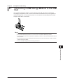
Connecting a USB Storage Medium to the USB Port....................................................... 9-1
Saving and Loading Data.................................................................................................. 9-2
Deleting and Copying Files............................................................................................... 9-5
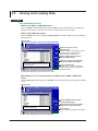
Changing File Names........................................................................................................ 9-7
Creating Folders................................................................................................................ 9-9
iii
App
Index
Contents
9.6
9.7
9.8
Deleting and Copying Folders......................................................................................... 9-10
Initializing the Internal Memory........................................................................................ 9-12
Printing............................................................................................................................ 9-13
Chapter 10 Other Operations
10.1
10.2
10.3
10.4
Configuring the Language, Beep, Start Menu, USB Function, and Screen Color........... 10-1
Configuring Power Save Settings.................................................................................... 10-2
Resetting the AQ1100 to Its Factory Default Settings..................................................... 10-3
Configuring Network Settings (Option)............................................................................ 10-4
Chapter 11 Troubleshooting, Maintenance, and Inspection
11.1
11.2
11.3
11.4
11.5
11.6
11.7
11.8
11.9
11.10
11.11
11.12
Appendix
If a Problem Occurs..........................................................................................................11-1
Error Messages................................................................................................................11-2
Viewing the Product Information......................................................................................11-5
Performing a Self Test......................................................................................................11-6
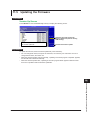
Updating the Firmware.....................................................................................................11-7
Performing a Mechanical Inspection and Checking Operations.......................................11-8
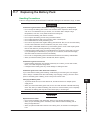
Replacing the Battery Pack..............................................................................................11-9
Replacing an Optical Adapter.........................................................................................11-12
Routine Maintenance.....................................................................................................11-14
Storage Precautions.......................................................................................................11-15
Recommended Replacement Parts...............................................................................11-16
Calibration......................................................................................................................11-17
Appendix 1
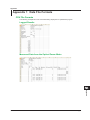
Data File Formats................................................................................................ App-1
Index
iv
IM AQ1100-01EN
Chapter 1
Features
1.1
Overview
1
Features
This instrument is an OLTS (Optical Loss Test Set) with the features listed below. It is used in the
optical fiber and line installation and maintenance servicing of access networks, which link telephone
exchanges and service providers with subscribers, and user networks, which enable communication
within a corporation or building.
• Optical power meter
• Loss-measurement light source and visible light source
• Loss measurement that makes use of its light source and optical power meter features (loss test).
• Efficient multicore loss testing for measuring loss in multicore fibers
• Simple IP testing through pinging (option)
2
3
4
AQ1100
5
Measurement in
cable installations
6
7
Optical fiber
Corporate user
8
Telephone exchanges
9
Consumer
10
11
App
Index
IM AQ1100-01EN
1-1
1.2
Optical Power Meter and Light Source
Optical Power Meter
The three instrument types listed below are available for measuring different types of optical power.
Suffix Code
-SPM
-HPM
-PPM
Optical Power Type
Standard
High input
PON (passive optical network)
If you are using the AQ1100 to measure optical power, the various settings listed below can be
configured.
Item
Wavelength
Wavelength mode1
Modulation mode2
Unit
Reference3
Measured value display hold
Measured value logging
Zero set4
Average count5
Maximum and minimum value
display6
Interlocking of light source and
optical power meter settings7
Offset8
Threshold9
Measurement of the optical
power from ONU to OLT for a
particular signal wavelength10
Measurement of the optical
power from OLT to ONU for a
particular signal wavelength11
Models with -SPM or
-HPM Suffix Codes
Yes
Yes
Yes
Yes (dB, dBm, W)
Yes
Yes
Yes
Yes
Yes
Models with -PPM Suffix Codes
Normal power meter
PON power meter
selected
selected
Fixed10, 11
Fixed10, 11
—
—
—
—
Yes (dB, dBm, W)
Yes (dBm, W)
Yes
—
Yes
Yes
Yes
—
Yes
Yes
Yes
Yes
Yes
Yes
—
Yes
Yes
—
Yes
Yes
Yes
Yes
Yes
Yes
—
—
Yes
—
—
Yes
Yes: Can be set or executed, —: Not available
1
2
3
4
5
6
7
8
9
10
11
1-2
Wavelengths can be set with the wavelength mode set to Simple, Detail, or CWDM.
• Simple: You can select from a list of preset wavelengths.
• Detail: You can set the wavelength to a value from 800 to 1700 nm in 1 nm steps.
• CWDM: You can set the wavelength to a value from 1270 to 1610 nm in 20 nm steps along the CWDM
wavelength grid.
You can select the modulation frequency of the incident rays from a list of presets. You can also select CW
(continuous).
You can make the displayed measured value the reference and display subsequent measured values as
relative values.
You can adjust the internal deviation of the optical power measurement section and obtain more accurate
absolute optical power values.
You can display averaged measured values.
You can display the maximum and minimum measured values.
You can interlock the light source and optical power meter settings when you connect an optical fiber
between the light source port of an AQ1100 and the optical power measurement port of another AQ1100.
You can add a specified value (the offset value) to measured optical power values.
You can set upper and lower threshold values and determine whether or not the measured values fall within
them.
You can measure the optical power of an upstream signal from the ONU (optical network unit: the user’s
optical terminal) to the OLT (optical line termination: the telephone exchange’s optical terminal). The optical
power of the 1310 nm (data wavelength) signal is measured.
You can measure the optical power of downstream signals from the OLT to the ONU. The optical power of
the 1490 nm (data wavelength) and 1550 nm (video wavelength) signals is measured.
IM AQ1100-01EN
1.2 Optical Power Meter and Light Source
1
Loss Measurement Light Source
Model
AQ1100A
AQ1100B
AQ1100D
Features
Three instrument models, with the measurement light wavelengths listed below, are available for
different applications.
Measurement Light Wavelength
SM 1310 nm, SM 1550 nm
SM 1310 nm, SM 1550 nm, SM 1625 nm
GI 850 nm, GI 1300 nm, SM 1310 nm, SM 1550 nm
2
You can produce continuous light or light that has been modulated at the selected frequency (modulation
mode).
Visible Light Source (Optional)
The visible light source is available on models with the /VLS option.
You can produce visible light to visually identify breaks in the optical fiber under test. You can turn the
visible light on and off independently of the measurement light source.
3
4
5
6
7
8
9
10
11
App
Index
IM AQ1100-01EN
1-3
1.3
Loss Testing
Optical fiber and optical line degradation can be measured easily.
You can measure optical loss with models with -SPM or -HPM suffix codes.
Auto Loss Testing (Using one AQ1100 as the light source and
another as the optical power meter)
Using the AQ1100 as a light source and optical power meter, you can easily measure optical fiber and
line degradation.
Light Source
You can set up to three measurement light wavelengths and produce them in order. You can
produce a constant level of light if you use the optical power adjustment feature.
Optical Power Meter
The AQ1100 automatically identifies the measurement light from the AQ1100 on the other side and
measures the optical power.
• The following items can be specified or executed. For details about these items, see section 1.2.
The unit, reference, offset, and threshold values can be specified.
The zero set and measured value display hold operations can be executed.
• You can attach fiber information to the measured values and save them.*
* Because the AQ1100 is capable of identifying optical fiber and line cores, it is possible to number cores
and tapes.
Optical power meter (AQ1100)
Light source (AQ1100)
Light source
port
Fiber under
loss test
Optical power
measurement
port
Loop-Back Loss Test (Using one AQ1100)
You can use the light source and optical power meter features on a single AQ1100 to perform a loopback loss test on an optical fiber or line. To perform loss testing, connect one end of the fiber that
you need to perform loss testing on to the AQ1100 light source port, and connect the other end to the
optical power measurement port of the same AQ1100.
Light source and Optical power meter (AQ1100)
1-4
Light source
port
Optical power
measurement
port
Fiber under loss test
IM AQ1100-01EN
1.4
Multicore Loss Testing
1
Features
2
Multicore optical fiber and optical line degradation can be measured efficiently.
You can measure optical loss with models with -SPM or -HPM suffix codes.
Master and Slave
To perform multicore testing, use one AQ1100 as an optical power meter master and another as a light
source slave.
Specifying the Optical Communication Fiber
To transfer, between the master and slave, project setup information and information about the fiber
under loss test, you must specify a fiber from the multicore optical fiber to use for communication.
Connect one end of the optical communication fiber to the master’s light source port (optical port 2),
and connect the other end to the slave’s optical power measurement port (optical port 1).
3
4
5
Information That Is Transferred from Master to Slave
The following information can be transferred through the optical communication fiber from the
master to the slave.
• Project information (see below for further details)
• Skipped cores (cores whose loss will not be tested)*
• Loss test results
6
* Because the AQ1100 is capable of identifying optical fiber and line cores, it is possible to number cores
and tapes.
Connecting the Optical Fiber under Loss Test
All fibers other than the optical communication fiber can be tested. For each optical fiber under
loss test, connect one end to the master’s optical power measurement port, and connect the other
end to the slave’s light source port. The core and tape numbers of the fibers under loss test are
transferred from the master to the slave.
Master (AQ1100)
Light source port
(optical port 2)
8
9
Slave (AQ1100)
Communication fiber
Optical power
measurement port
Fiber under
loss test
Optical power
measurement port
(optical port 1)
10
Light source port
11
Executing a Loss Test
Transmit light from the slave. The master will automatically identify up to three different wavelengths
in the light from the slave and measure the optical power. Continue the loss test, switching the cores
between the master and the slave in order.
Projects
You can create projects with the master. You can specify the following project information:
The project name, the number of the core to start loss testing at, the tape number type, the number
of cores, and the transmitted or measured measurement light wavelengths (up to 3).
• You can transfer projects from the master to the slave and share information.
• When the master and the slave share a project and use that project to perform loss testing, if testing
is stopped, the data up to the stop point is saved and you can begin testing again from the next
core.
• You can save and load projects as CSV files.
IM AQ1100-01EN
7
1-5
App
Index
1.5
IP Testing (Option)
You can check whether or not the network layer of an Ethernet LAN line is established. Before
performing an IP test, make sure that the physical layer of the optical fiber or line is connected.
IP testing is available on models with the /LAN option.
Pinging
To ping an address (perform a simple IP test), specify the address and configure the Tx frame settings
listed below. The results of pinging the address appear on the screen.
The frame length, Tx mode (continuation, number of frames to send, and transmission time), and
measurement interval
1-6
IM AQ1100-01EN
1.6
Other Features
1
Features
2
In addition to the features described so far, the AQ1100 also has the following features.
• Data saving and loading
• Language selection
3
• Beep on/off
• Startup menu selection
• USB function selection (storage/communication)
4
• Screen color selection
• Current date and time configuration (see the operation guide, IM AQ1100-02EN)
• Power save settings
5
• Network settings (on models with the /LAN option)
• Setup information initialization (to the factory default values)
• AQ1100 information display (model, serial no., suffix code, version, etc.)
6
• Self test execution
• Firmware version updating
7
8
9
10
11
App
Index
IM AQ1100-01EN
1-7
Chapter 2
Common Operations
2.1
1
To make this manual easier to read, we have omitted or simplified explanations of the kinds of
operations listed below.
• Repetitive operations
• Detailed operations for proceeding to the desired setup menu or dialog box and information about
the accompanying screen changes.
• Setup items that users can configure if they have a general understanding of them.
2
Below, we will compare examples of detailed setup operation explanations with explanations that have
been omitted or simplified.
Common Operations
Key, Rotary Knob, and Arrow Key Operations
3
4
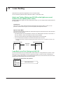
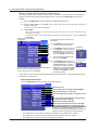
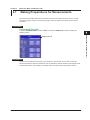
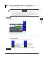
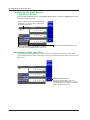
Key Operations
The examples below explain the process for turning on the power, waiting for the top menu to appear,
and then opening the Save Data menu. The first menu in the figure below is the top menu for models
with -SPM or -HPM suffix codes.
5
1. Press the OPM LS soft key ( F1 ) to display the OPM LS menu.
2. Press the Save Data soft key ( F4 ) to display the Save Data menu.
6
Menu operation types A through C are listed below.
A
B
A
C
MENU
ESC
MENU
C
A: A selection menu appears when you press
the soft key. When you press a soft key that
corresponds to an item on the menu, the
selected item is confirmed, or the action that
corresponds to it is performed.
B: The selected setting switches each time you
press the soft key.
C: When you press the soft key, the item that
corresponds to it is confirmed, or the action
that corresponds to it is performed.
7
8
9
To return to the previous menu, press ESC.
To return to the top menu, press MENU.
In this manual, steps 1 and 2 listed above and the setup operations in the menu that follows them are
written as shown below.
10
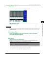
Setup Operation Example
11
Press the OPM LS soft key and then the Data Save soft key to display the following screen.
In the menu that appears, turn the light
source or visible light source on or off.
Set the list to show (Core List, List).
In the menu that appears, execute the
deletion of the selected data.
Executes skipping
App
At this point, the soft key names are
omitted, and the settings that the soft keys
are used to configure and the actions
that pressing them causes are explained.
Options and ranges are listed afterwards.
Index
Saves data
• Step numbers are used when there are many operations and when operations must be
performed in different menus.
• The explanation for returning to the previous menu is omitted.
IM AQ1100-01EN
2-1
2.1 Key, Rotary Knob, and Arrow Key Operations
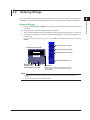
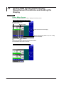
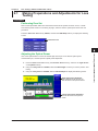
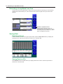
Rotary Knob and Arrow Key Operations
This section explains how to operate a menu and the operations to perform when a setup dialog box
appears. We will use the dialog box that appears when you press the OPM Setup soft key as an
example.
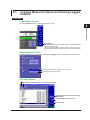
1. Press the OPM Setup soft key to display the OPM Setup dialog box.
2. Use the rotary knob or the arrow keys to move the cursor to the item that you need to
configure or execute.
The item at the cursor location is highlighted.
3. Press ENTER.
• Next, follow the instructions in the figure below that correspond to the type of item that you are
configuring or executing.
• In this manual, steps 2 and 3 listed above are indicated using the expression “using the rotary knob
and ENTER.”
The item at the cursor location
Setup operation types D through G are
is highlighted.
listed below.
D
E
E
F
F
G
G
D: Press ENTER to confirm the item or
execute its corresponding action.
Example of
E: Press ENTER to display a menu. Turn
menu for E
the rotary knob or press the up and
down arrow keys to move the cursor
to the item that you want to select.
Then press ENTER to select the item.
F: The selected setting switches each
time you press ENTER.
Example of text
G: Press ENTER to display a text box.
box for G
Turn the rotary knob or press the up
and down arrow keys to increase
or decrease a number. To move between digits, press the left and right
For setup operation types E and G, to reset the selected
arrow keys. After you have entered
item to its previous settings, press ESC.
a number, press ENTER to set the
To return to the top menu, press MENU.
value to that number.
G
In this manual, steps 1 through 3 listed above and the setup operations in the menu that follows them
are written as shown below.
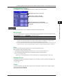
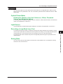
Setup Operation Example
Press the OPM Setup soft key to display the following screen.
Performs zero set
Set the wavelength mode (Simple, Detail, CWDM).
Set the average count (1, 10, 50, 100).
Turns the display of the max/min value menu on and
off
Turns on and off the interlocking of the light source
and optical power meter settings
Set the offset (–9.900 to 9.900 dB).
Set the upper threshold value (–80.00 to 40.00 dB).
Set the lower threshold value (–80.00 to 40.00 dB).
At this point, the settings that the items are used to
configure and the actions that selecting them causes are
explained. Options and ranges are listed afterwards.
• The explanations of rotary knob, arrow key, and ENTER key operations are omitted.
• The explanation of how to reset the selected item to its previous setting is omitted.
• The explanation for returning to the previous menu is omitted.
2-2
IM AQ1100-01EN
2.2
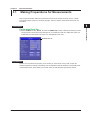
Entering Strings
1
After you have selected a setup item and pressed ENTER, a character input dialog box will appear if it
is necessary. This section explains the operations that you can perform after the dialog box appears.
2
3. After you have finished entering and editing the string, press the OK soft key to confirm the
Common Operations
You can also confirm the string by moving the cursor to ENT on the displayed keyboard and then pressing
ENTER.
5
Entering Strings
1. Using the rotary knob and ENTER, enter a string. The string that you entered appears in the
edit screen.
2. Press the various soft keys to edit the string as necessary.
string that you entered and close the character input dialog box. The string be applied to the
relevant item.
Moves the cursor to the left
3
4
6
Character input dialog box
Moves the cursor to the right
Edit screen
7
Deletes the previous character
Keyboard
8
Confirms the entered string
Switches between
Space
uppercase and
Confirms
lowercase letters the input
Input history
Strings that you have entered in the past remain in
the input history. You can enter these strings (see
the next page).
9
10
Note
• If there is a limit to the length of the string, you will not be able to enter characters after the limit is
reached.
• You can also enter strings using a USB keyboard.
11
App
Index
IM AQ1100-01EN
2-3
2.2 Entering Strings
Entering Strings from the History
1. Using the rotary knob and ENTER, select
to display the input history screen.
2. Using the rotary knob and ENTER, choose the string that you want to enter. The string
appears in the edit screen.
Note
Entered strings are saved to the input history when you confirm them. Up to 50 strings can be saved. Newer
strings appear at the top of the input history.
2-4
IM AQ1100-01EN
Chapter 3
3.1
Optical Power Meter
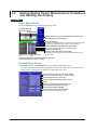
Making Preparations for Measurements
1
2
Remove the optical fiber cables from the AQ1100 and close the optical connector covers, or make
sure that the power meter is not receiving any light, and then start the optical power meter zero set
procedure.
3
Procedure
Press the OPM LS soft key, SETUP, and then the OPM Setup soft key to display the following screen.
The figure below shows the screen that appears on models with -SPM and -HPM suffix codes. On
models with the -PPM suffix code, there is no “Wavelength mode” item.
Performs zero set
Optical Power Meter
Performing Zero Set
4
5
6
7
8
Explanation
Perform zero set whenever necessary, such as after you have turned on the power or when the
ambient temperature changes. Performing zero set adjusts the internal deviation of the optical power
measurement section and enables you to obtain more accurate absolute optical power values.
9
10
11
App
Index
IM AQ1100-01EN
3-1
3.2
Setting Optical Power Measurement Conditions
and Holding the Display
Procedure
Power Meter Screen
Press the OPM LS soft key to display the following screen.
Bar graph display of
the measured value
Measured value
Sets the reference to the currently displayed measured value
Holds the measured value display
Set the wavelength.
This setting varies depending on the model or the wavelength mode
that you set in the detailed setup screen in the next section.
Set the modulation mode (CW, 270Hz, 1kHz, 2kHz).
Can be set on models with -SPM or -HPM suffix codes.
Set the unit (dB, dBm, W).
Set the reference manually (–80 to 40 dBm).
The Reference box appears if you press the DREF soft key or set
the unit to dB.
Lower threshold Upper threshold
line
line
These lines indicate the upper and lower threshold values
(see the detailed setup screen in section).
Detailed Setup Screen
Press SETUP and then the OPM SETUP soft key to display the following screen.
The figure below shows the screen that appears on models with -SPM and -HPM suffix codes. On
models with the -PPM suffix code, there is no “Wavelength mode” item.
Set the wavelength mode (Simple, Detail, CWDM).
Can be set on models with -SPM or -HPM suffix codes.
Set the average count (1, 10, 50, 100).
Turns the display of the max/min value menu on
and off
Turns the interlocking of the light source and
optical power meter settings on and off
Set the offset (–9.900 to 9.900 dB).
Set the threshold values (–80 to 40 dBm).
You can set the upper and lower values.
3-2
IM AQ1100-01EN
3.2 Setting Optical Power Measurement Conditions and Holding the Display
1
Explanation
Wavelength
The light receiving element of the optical power measurement section has a wavelength sensitivity
characteristic. The AQ1100 measures optical power more accurately by adjusting the sensitivity
according to the specified wavelength. The measurable wavelength range varies depending on the
model.
2
3
Models with -SPM or -HPM Suffix Codes
Wavelength Mode
Simple
Detail
CWDM
Optical Power Meter
The wavelength ranges and steps vary depending on the wavelength mode that you set in the
detailed setup screen. You can set the wavelength within the following ranges.
Range and Steps
You can select from 850 nm, 1300 nm, 1310 nm, 1490 nm, 1550 nm, 1625 nm, and
1650 nm.
You can set the wavelength to a value from 800 to 1700 nm in 1 nm steps.
You can set the wavelength to a value from 1270 to 1610 nm in 20 nm steps.
4
5
Models with -PPM Suffix Codes
You can set the wavelength to one of the following values.
1310 nm, 1490 nm, 1550 nm
6
Modulation Mode
On models with -SPM or -HPM suffix codes, you can set the modulation mode for optical measurement
to one of the following options.
CW (continuous light), 270 Hz, 1 kHz, 2 kHz
7
Unit
You can set the optical power display unit to one of the following options.
dB (relative value), dBm (absolute value), W (absolute value)
• The following prefixes are attached to W: m (10–3), m (10–6), n (10–9), and p (10–12).
• The relationship between the absolute values dBm and W is indicated below.
PdBm = 10 × log (Pw × 103)
Where PdBm is the optical power in units of dBm and Pw is the optical power in units of W.
8
9
Reference
You can set a reference and display measured values as relative values (display their difference from
the reference).
• Press the DREF soft key to make the displayed measured value the reference and display
subsequent measured values as relative values. The unit will change to dB.
• Press the DREF soft key or set the unit to dB to display the Reference box in the Power Meter
screen.
• You can set the reference manually in the Reference box. The range is –80 to 40 dBm.
• If you set the unit to dBm or W, the Reference box disappears and the measured values are
displayed as absolute values.
10
11
App
Wavelength Mode
On models with the -SPM and -HPM suffixes, you can set the mode to one of the following options.
Simple, Detail, CWDM
When you change the wavelength mode, the wavelength range and steps for the Wavelength item
change as explained above.
Average Count
Averages of the measured values are displayed. You can set the number of values to average to one
of the following options.
1, 10, 50, 100
IM AQ1100-01EN
3-3
Index
3.2 Setting Optical Power Measurement Conditions and Holding the Display
Turning the Maximum and Minimum Value Menu On and Off
In the Power Meter screen, you can display a menu that shows the maximum (Max) and minimum (Min)
measured values.
On
Off
The menu is displayed.
The menu is not displayed.
Turning the Maximum and Minimum Value Display On and Off
In the menu that appears in the Power Meter screen, you can start the display of the maximum and
minimum measured values. The maximum and minimum value displays are constantly updated
while measurement is being performed.
On
Off
The maximum and minimum measured values from the time that you selected On are constantly
updated and displayed.
The maximum and minimum values are not displayed. The maximum and minimum values are
reset when you select Off.
Measured value
Maximum value
Minimum value
Turns the max/min value display on and off
Turning the Interlocking of the Light Source and Optical Power
Meter Settings On and Off
You can connect an optical fiber between the light source port of an AQ1100 and the optical power
measurement port of another AQ1100 and use this setting so that the power meter settings are
synchronized to the light source wavelength and modulation mode settings.
On
Off
After On is selected, the power meter settings are synchronized to the light source settings.
The power meter settings are not synchronized to the light source settings.
Offset
The value that you specify (the offset value) is added to the measured optical power values that are
displayed.
The range is –9.900 to 9.900 dB.
Threshold Value
You can set upper and lower threshold values and determine whether or not the measured values fall
within them.
• The range for the upper and lower threshold values is –80 to 40 dBm. You must set the values so
that the upper threshold value is greater than the lower threshold value.
• When a measured value is within the upper and lower thresholds, its bar graph is green.
• When a measured value exceeds the upper threshold or falls below the lower threshold, its bar
graph is red.
Holding the Measured Value Display
When you press the HOLD soft key, the following actions are held: the updating of the measured
values, bar graph, and maximum and minimum values and the showing or hiding of the maximum and
minimum value display. The values at the time that you pressed the HOLD soft key remain displayed.
To release the hold on the display, press the HOLD soft key again.
The display is being held.
Not updated
3-4
IM AQ1100-01EN
3.3
Logging Measured Values and Saving Logged
Results
1
2
Procedure
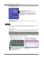
Power Meter Screen
Press the OPM LS soft key to display the following screen.
3
Optical Power Meter
4
5
Starts logging
Set the measurement interval and the log count in the detailed setup
screen in the next section.
After the specified number of logs are recorded, a screen for saving
the logged results appears (see the file save screen explained later).
Detailed Setup Screen
Press the SETUP soft key and then the Data Save Logging soft key to display the following screen.
6
7
8
9
Set the measurement interval (500ms, 1s, 2s, 5s, 10s).
Set the logging count (10 to 1000).
10
File Save Screen
11
The path of the destination directory
The number of folders and files in the destination directory
App
Set the destination drive (internal memory,
USB memory).
Set the file name (see section 9.2).
Saves the data
The file name candidate for the next save operation
IM AQ1100-01EN
3-5
Index
3.3 Logging Measured Values and Saving Logged Results
Explanation
Creating and Saving Logs
The AQ1100 is always measuring power when the Power Meter screen is displayed. To save the
measured values, you must log them.
• To start logging, press the Logging START soft key. During logging, on the menu, “Logging START”
changes to “Logging STOP.” All soft keys other than the Logging STOP soft key are unavailable.
• Logging stops when the specified number of logs are recorded or when you press the Logging
STOP soft key. Then, on the menu, “Logging STOP” changes to “Logging START,” and the file save
screen appears.
• You can save logged results in CSV format.
Measurement Interval
You can set the interval for logging measured values to one of the following values.
500 ms, 1 s, 2 s, 5 s, 10 s
Logging Count
You can set the number of values to log within the following range.
10 to 1000
Drive to Save To
You can set the destination drive to one of the following options.
Internal memory, USB memory
You can set the destination drive to the USB memory when, in the Common screen for miscellaneous
features (described later in this manual), you have set USB Function to Storage.
File Name
You can specify file names by combining comments and numbers. For details, see section 9.2.
For an example of the saved data being displayed using spreadsheet software, see appendix 2.
3-6
IM AQ1100-01EN
3.4
Selecting and Saving Core and Tape Numbers
1
2
Procedure
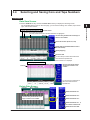
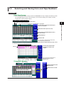
Data Save Screen
Press the OPM LS soft key and then the Data Save soft key to display the following screen.
On the detailed setup screen on the next page, you can set the starting core number, tape number
type, and number of fibers.
Optical Power Meter
When “Display” is set to “Core List”
Check mark indicating that the data has been saved
Skipped core numbers are dimmed.
The core number that is set as the save destination is highlighted.
Core no.
Use the rotary knob and the arrow keys to
select a core number.
3
4
5
Set the list to show (Core List, List).
Delete data (see the Delete Data screen in
the next section).
6
Specify skipping.
Save area
7
Saves the data
You can save up to three sets of data in the
save area of the specified core.
8
Data (measurement conditions and measured values) The data set in section 3.2 is displayed.
When “Display” is set to “List”
Core no.
Save area
Use the rotary knob and the
arrow keys to select a core
number.
9
10
You can save up to three sets of
data in the save area of the
specified core.
Delete Data Screen
Core no.
11
App
No. 1, 2, and 3
Deletes the data at no. 1
Index
Deletes the data at no. 2
Use the rotary knob and the arrow
keys to select a core number.
Deletes the data at no. 3
Deletes the data at no. 1, 2,
and 3 of the selected core
Deletes all the core data
IM AQ1100-01EN
3-7
3.4 Selecting and Saving Core and Tape Numbers
Detailed Setup Screen
Press the SETUP soft key and then the Data Save Logging soft key to display the following screen.
Set the starting core number (1 to 9900).
Set the tape number type (Off, a-b(2), a-c(3), a-d(4), a-e(5),
a-f(6), a-g(7), a-h(8)).
Set the number of fibers or tapes (up to 100 fibers when
Tape no. Type is set to Off, up to 50 tapes when Tape no.
Type is set to a-b(2), ..., up to 12 tapes when Tape no. Type
is set to a-h(8)).
Saving Data to a File
Press SETUP and then the File soft key to display the file save screen. Follow the procedure in
section 9.2 to save the data.
Explanation
You can specify core numbers and tape number types and save data (measurement conditions and
measured values) to the AQ1100 internal memory. You can also save the data to a file.
Displayed List
You can set the list to show to one of the following options. The list display format changes depending
on the starting core number, tape number type, and number of fibers (or tapes) that you set in the
detailed setup screen.
Core List
List
A list of core numbers and the saved data of the highlighted core number are displayed.
The core numbers and saved data are displayed.
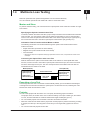
Example When the Starting Core Number Is Set to “5,” the Tape Number Type Is Set
to “a-h(8),” and the Number of Tapes Is Set to “10”
Core List
The list begins with the starting core number 5.
Each core number is divided into eight tape
numbers from a to h.
List
The list begins with the starting core number 5.
Each core number is divided into eight tape
numbers from a to h. The data for the core and
tape number pairs through 14h is displayed.
The data of the highlighted core and tape
number pair (5a here) is displayed.
There are 10 tapes, so the cores are
numbered 5a through 14h.
Use the rotary knob and the arrow keys to scroll
through the list.
3-8
IM AQ1100-01EN
3.4 Selecting and Saving Core and Tape Numbers
1
Skipping
If you specify Skip for a core number that you don’t need to measure, its data will not be saved. By
setting which cores to skip beforehand, you can avoid accidentally saving unnecessary data.
2
Saving Data
You can save up to three sets of data in the save area of the specified core.
For details about saving the data to a file, see section 9.2.
3
Optical Power Meter
Deleting Data
You can delete the data for individual core numbers in a save area or delete all the data at once.
4
Starting Core Number
You can set the starting core number to a value within the following range.
1 to 9900
5
Tape Number Type
You can set the tape number type to one of the following options.
Off, a-b(2), a-c(3), a-d(4), a-e(5), a-f(6), a-g(7), a-h(8)
6
Number of Fibers or Tapes
You can set the number of fibers or tapes to a value within one of the following ranges.
Tape Number Type
Off
a-b(2)
a-c(3)
a-d(4)
a-e(5)
a-f(6)
a-g(7)
a-h(8)
7
Number of Fibers or Tapes
10 to 100 fibers
10 to 50 tapes
10 to 33 tapes
10 to 25 tapes
10 to 20 tapes
10 to 16 tapes
10 to 14 tapes
10 to 12 tapes
8
9
10
11
App
Index
IM AQ1100-01EN
3-9
Chapter 4
4.1
PON Power Meter (-PPM suffix code)
Making Preparations for Measurements
1
2
Remove the optical fiber cables from the AQ1100 and close the optical connector covers, or make
sure that the power meter is not receiving any light, and then start the PON power meter zero set
procedure.
3
Procedure
Performing Zero Set
Press the PON Power Meter soft key, SETUP, and then the OPM Setup soft key to display the
following screen.
4
PON Power Meter (-PPM suffix code)
Performs zero set
5
6
7
Explanation
Perform zero set whenever necessary, such as after you have turned on the power or when the
ambient temperature changes. Performing zero set adjusts the internal deviation of the optical power
measurement section and enables you to obtain more accurate absolute optical power values.
8
9
10
11
App
Index
IM AQ1100-01EN
4-1
4.2
Setting PON System Optical Power
Measurement Conditions and Holding the
Display
Procedure
Power Meter Screen
Press the PON Power Meter soft key to display the following screen.
When the Signal Direction Is ONU -> OLT
Bar graph display of the
measured value
Measured value
Holds the measured value display
Set the signal direction (ONU -> OLT, OLT -> ONU).
Set the unit (dB, W).
Lower threshold Upper threshold
line
line
These lines indicate the upper and lower threshold values
(see the detailed setup screen in section).
When the Signal Direction Is OLT -> ONU
4-2
IM AQ1100-01EN
4.2 Setting PON System Optical Power Measurement Conditions and Holding the Display
1
Detailed Setup Screen
Press SETUP and then the OPM SETUP soft key to display the following screen.
2
Set the average count (1, 10, 50, 100).
Set the offset (–9.900 to 9.900 dB).
Set it for each PON system wavelength.
3
4
PON Power Meter (-PPM suffix code)
Set the threshold values (–80 to 40 dBm).
Set the upper and lower limits for each PON system
wavelength.
5
Explanation
The PON power meter is only available on models with -PPM suffix codes.
6
Wavelength
The wavelengths that you can specify when measuring the optical power of a PON system are listed
below. The wavelengths vary depending on the signal direction.
Signal Direction
ONU -> OLT1
OLT -> ONU2
Wavelength
1310 nm
1490 nm and 1550 nm
1 You can measure the optical power of the upstream signal wavelength from the ONU (optical network
unit: the user’s optical terminal) to the OLT (optical line termination: the telephone exchange’s optical
terminal). The optical power of the 1310 nm (data wavelength) signal is measured.
2 You can measure the optical power of the downstream signal wavelengths from the OLT to the ONU. The
optical power of the 1490 nm (data wavelength) and 1550 nm (video wavelength) signals is measured.
Unit
You can set the optical power display unit to one of the following options.
dBm (absolute value), W (absolute value)
• The following prefixes are attached to W: m (10–3), m (10–6), n (10–9), and p (10–12).
• The relationship between the absolute values dBm and W is indicated below.
PdBm = 10 × log (Pw × 103)
Where PdBm is the optical power in units of dBm and Pw is the optical power in units of W.
7
8
9
10
11
Average Count
Averages of the measured values are displayed. You can set the number of values to average to one
of the following options.
1, 10, 50, 100
Index
Offset
For each wavelength, the value that you specify (the offset value) is added to the measured optical
power values that are displayed.
The range is –9.900 to 9.900 dB.
IM AQ1100-01EN
App
4-3
4.2 Setting PON System Optical Power Measurement Conditions and Holding the Display
Threshold Value
For each wavelength, you can set upper and lower threshold values and determine whether or not the
measured values fall within them.
• The range for the upper and lower threshold values is –80 to 40 dBm. You must set the values so
that the upper threshold value is greater than the lower threshold value.
• When a measured value is within the upper and lower thresholds, its bar graph is green. “PASS”
appears in the measured value area.
• When a measured value exceeds the upper threshold or falls below the lower threshold, its bar
graph is red. “FAIL” appears in the measured value area.
Holding the Measured Value Display
When you press the HOLD soft key, the updating of the measured values and bar graph is held. The
values at the time that you pressed the HOLD soft key remain displayed. To release the hold on the
display, press the HOLD soft key again.
The display is being held.
Not updated
4-4
IM AQ1100-01EN
4.3
Selecting and Saving Core and Tape Numbers
1
2
Procedure
Data Save Screen
Press the PON Power Meter soft key and then the Data Save soft key to display the following screen.
On the detailed setup screen on the next page, you can set the starting core number, the tape
number type, and the number of fibers.
When “Display” is set to “Core List”
Check mark indicating that the data has been saved
Skipped core numbers are dimmed.
The core number that is set as the save destination is highlighted.
Core no.
Use the rotary knob and the arrow keys to
select a core number.
4
PON Power Meter (-PPM suffix code)
5
Set the list to show (Core List, List).
6
Delete data (see the Delete Data screen in
the next section).
Specify skipping.
Save area
3
7
Saves the data
You can save up to three sets of data in the
save area of the specified core.
Example of the data (measurement conditions and measured values) when the signal direction is ONU -> OLT
The data set in section 4.2 is displayed.
8
When “Display” is set to “List”
Core no.
Save area
Use the rotary knob and the
arrow keys to select a core
number.
9
10
11
You can save up to three sets of
data in the save area of the
specified core.
Delete Data Screen
Core no.
App
No. 1, 2, and 3
Deletes the data of all the
selected cores
Deletes all the core data
Use the rotary knob and the arrow
keys to select a core number.
IM AQ1100-01EN
4-5
Index
4.3 Selecting and Saving Core and Tape Numbers
Detailed Setup Screen
Press the SETUP soft key and then the Save Data soft key to display the following screen.
Set the starting core number (1 to 9900).
Set the tape number type (Off, a-b(2), a-c(3), a-d(4), a-e(5),
a-f(6), a-g(7), a-h(8)).
Set the number of fibers or tapes (up to 100 fibers when
Tape no. Type is set to Off, up to 50 tapes when Tape no.
Type is set to a-b(2), ..., up to 12 tapes when Tape no. Type
is set to a-h(8)).
Saving Data to a File
Press SETUP and then the File soft key to display the file save screen. Follow the procedure in
section 9.2 to save the data.
Explanation
The PON power meter is only available on models with -PPM suffix codes.
You can specify core numbers and tape number types and save data (measurement conditions and
measured values) to the AQ1100 internal memory. You can also save the data to a file.
Displayed List
You can set the list to show to one of the following options. The list display format changes depending
on the starting core number, tape number type, and number of fibers (or tapes) that you set in the
detailed setup screen.
Core List
List
A list of core numbers and the saved data of the highlighted core number are displayed.
The core numbers and saved data are displayed.
Example When the Starting Core Number Is Set to “5,” the Tape Number Type Is Set
to “a-h(8),” and the Number of Tapes Is Set to “10”
Core List
List
The list begins with the starting core number 5.
Each core number is divided into eight tape
numbers from a to h.
The list begins with the starting core number 5.
Each core number is divided into eight tape
numbers from a to h. The data for the core and
tape number pairs through 14h is displayed.
The data of the highlighted core and tape
number pair (5a here) is displayed.
There are 10 tapes, so the cores are
numbered 5a through 14h.
Use the rotary knob and the arrow keys to scroll
through the list.
4-6
IM AQ1100-01EN
4.3 Selecting and Saving Core and Tape Numbers
1
Skipping
If you specify Skip for a core number that you don’t need to measure, its data will not be saved. By
setting which cores to skip beforehand, you can avoid accidentally saving unnecessary data.
2
Saving Data
You can save up to three sets of data in the save area of the specified core. When the signal direction
is from the OLT to the ONU, you can save the data for two wavelengths at the same time.
For details about saving the data to a file, see section 9.2.
You can delete the data for individual core numbers in a save area or delete all the data at once.
4
Starting Core Number
PON Power Meter (-PPM suffix code)
Deleting Data
3
You can set the starting core number to a value within the following range.
1 to 9900
5
Tape Number Type
6
You can set the tape number type to one of the following options.
Off, a-b(2), a-c(3), a-d(4), a-e(5), a-f(6), a-g(7), a-h(8)
Number of Fibers or Tapes
7
You can set the number of fibers or tapes to a value within one of the following ranges.
Tape Number Type
Off
a-b(2)
a-c(3)
a-d(4)
a-e(5)
a-f(6)
a-g(7)
a-h(8)
Number of Fibers or Tapes
10 to 100 fibers
10 to 50 tapes
10 to 33 tapes
10 to 25 tapes
10 to 20 tapes
10 to 16 tapes
10 to 14 tapes
10 to 12 tapes
8
9
10
11
App
Index
IM AQ1100-01EN
4-7
Chapter 5
5.1
Light Source
Producing Measurement Light
1
2
WARNING
• While the AQ1100 is producing light, do not remove the optical fiber cable, because light is
emitted from the light source port. Visual impairment may occur if the light enters the eye.
• Close the covers of any light source ports that do not have optical fiber cables connected
to them. On models with two or more light source ports, visual impairment may occur if light
that is mistakenly emitted from the wrong port enters the eye.
3
4
Procedure
Light Source Screen
5
Press the OPM LS soft key to display the following screen.
Light Source
The wavelength and modulation mode of
the emitted light
6
7
8
9
Set the modulation mode (CW, 270Hz, 1kHz, 2kHz).
The available settings vary depending on the model. For details, see the explanation later
in this section.
Set the wavelength.
The available settings vary depending on the model. For details, see the explanation later
in this section.
10
Turning the Light Source On and Off
Turn the light source on after you set the wavelength and the modulation mode.
Pressing the LS Key
Press LS to turn on the measurement light. A mark appears on the AQ1100 display to indicate
that the light is on.
Press LS while the light is on. The light turns off. The light mark disappears.
App
Pressing the Soft Key
11
Press the LS VLS ON/OFF soft key to display the following menu.
Index
Turns the light on
The measurement light
turns on. A mark appears
on the AQ1100 display to
indicate that the light is on.
Turns the light off
The light turns off. The
light mark disappears.
While the above menu is displayed, you can also turn the light on and off by pressing LS.
IM AQ1100-01EN
5-1
5.1 Producing Measurement Light
Explanation
Measurement Light Wavelength
There are three instrument types, with the measurement light wavelengths listed below. Select a
wavelength from the available settings on the AQ1100 that you are using.
Model
AQ1100A
AQ1100B
AQ1100D
Measurement Light Wavelength
SM 1310 nm, SM 1550 nm
SM 1310 nm, SM 1550 nm, SM 1625 nm
GI 850 nm, GI 1300 nm, SM 1310 nm, SM 1550 nm
The light for single mode (SM) optical fiber is emitted from optical port 2. The light for graded-index (GI)
multi-mode optical fiber is emitted from optical port 3. Firmly connect the optical fiber to the port from
which the light with the selected wavelength will be transmitted.
Modulation Mode
You can set the frequency of the light to one of the following options.
CW (continuous light), 270 Hz, 1 kHz, 2 kHz
On the AQ1100D, when the wavelength is GI 850 nm or GI 1300 nm, you can set the modulation mode
to CW or 270 Hz.
5-2
IM AQ1100-01EN
5.2
Turning On the Visible Light (Option)
1
2
WARNING
• While the AQ1100 is producing light, light is emitted from the light source port. Do not look
directly at this light. Visual impairment may occur if the light enters the eye.
• Close the covers of any light source ports that do not have optical fiber cables connected
to them. On models with two or more light source ports, visual impairment may occur if light
that is mistakenly emitted from the wrong port enters the eye.
3
4
Procedure
5
Light Source Screen
Light Source
Press the OPM LS soft key to display the following screen.
6
7
8
9
Turning the Light Source On and Off
Pressing the VLS Key
Press VLS to turn on the visible light. A mark appears on the AQ1100 display to indicate that
the light is on.
Press VLS while the light is on. The light turns off. The light mark disappears.
Pressing the Soft Key
10
11
Press the LS VLS ON/OFF soft key to display the following menu.
App
Turns the light on
The visible light turns on.
A mark appears on the
AQ1100 display to
indicate that the light is on.
Turns the light off
The light turns off. The
light mark disappears.
Index
While the above menu is displayed, you can also turn the light on and off by pressing VLS.
Explanation
The visible light source is available on models with the /VLS option.
Visible light is emitted from the visible light source port (optical port 4).
IM AQ1100-01EN
5-3
Chapter 6
Loss Testing (-SPM and -HPM suffix codes)
6.1
Making Preparations and Adjustments for Loss
Testing
1
2
Procedure
Performing Zero Set
Remove the optical fiber cables from the AQ1100 and close the optical connector covers, or make
sure that the power meter is not receiving any light, and then start the optical power meter zero set
procedure.
3
Press the Auto Loss Test soft key, SETUP, and then the OPM Setup soft key to display the following
screen.
4
Performs zero set
5
6
Use a short optical fiber to connect an AQ1100 light source port to an AQ1100 optical power
measurement port, and then perform optical power adjustment.
Loss Testing (-SPM and -HPM suffix codes)
Adjusting the Optical Power
7
1. Press the Auto Loss Test soft key, the Function Select soft key, and then the Light Source
or Loop Back soft key.
2. Using the rotary knob and ENTER, select the Wavelength at which you need to perform loss
testing.
3. Using the rotary knob and ENTER, select LS Power Adjust to display the following screen.
Starts optical power adjustment
When adjustment ends normally, the
AQ1100 returns to the previous screen.
8
9
10
11
Cancels optical power adjustment
The AQ1100 returns to the previous
screen.
App
Index
IM AQ1100-01EN
6-1
6.1 Making Preparations and Adjustments for Loss Testing
Explanation
Zero Set
Perform zero set whenever necessary, such as after you have turned on the power or when the
ambient temperature changes. Performing zero set adjusts the internal deviation of the optical power
measurement section and enables you to obtain more accurate absolute optical power values. Perform
zero set on both the optical power meter and the light source.
Optical Power Adjustment
Adjust the optical power of the light source as necessary.
When you execute optical power adjustment, the AQ1100 automatically identifies the optical power
level and adjusts itself accordingly. Perform optical power adjustment on the light source.
• Optical power adjustment begins when you press the Execute soft key. When it ends normally, the
AQ1100 returns to the previous screen. During adjustment, “Execute” changes to “Abort.” All soft
keys other than the Abort soft key are unavailable.
• Press the Abort soft key to stop optical power adjustment. “Abort” will change to “Execute.” The
adjustment value will return to the value that it was at before adjustment was executed.
• Connect a short optical fiber of a few meters or less in length. Make sure that the fiber is free from
dirt, scratches, bends, and other potential causes of optical degradation.
• The initial adjustment value is the factory default setting.
6-2
IM AQ1100-01EN
6.2
Performing an Auto Loss Test
1
2
Procedure
Configuring the Optical Power Meter
Power Meter Screen
Press the Auto Loss Test soft key, the Function Select soft key, and then the Power Meter soft key
to display the following screen.
Bar graph display of the
measured value
Measured value
3
4
Set the reference manually (–80 to 40 dBm).
The Reference box appears if you press the DREF soft key or set
the unit to dB.
Sets the reference to the currently displayed measured value
5
Holds the measured value display
6
Loss Testing (-SPM and -HPM suffix codes)
7
Set the unit (dB, dBm, W).
Lower threshold Upper threshold
line
line
These lines indicate the upper and lower threshold values
(see the detailed setup screen in section).
8
Detailed Setup Screen
Press SETUP and then the OPM SETUP soft key to display the following screen.
9
Set the offset (–9.900 to 9.900 dB).
10
Set the threshold values (–80 to 40 dBm).
You can set the upper and lower values.
11
App
Index
IM AQ1100-01EN
6-3
6.2 Performing an Auto Loss Test
Configuring the Light Source
Light Source Screen
Press the Auto Loss Test soft key, the Function Select soft key, and then the Light Source soft key
to display the following screen.
When you start a loss test, the AQ1100 produces
wavelengths 1, 2, and 3 in order, and the current
wavelength appears here.
Set the wavelength.
The available settings vary depending on the model.
For details, see the explanation later in this section.
Optical power adjustment (see section 6.1)
Executing an Auto Loss Test
Connect one end of the optical fiber or line that you need to perform loss testing on to the optical
power measurement port of the power meter, and connect the other end to the light source port of the
light source.
Executes an auto loss test
The light source produces, in order, the
wavelengths that you specified for 1, 2, and 3.
The optical power meter measures the optical
power of the light that it receives.
6-4
IM AQ1100-01EN
6.2 Performing an Auto Loss Test
1
Saving Data
Data Save Screen
In the Power Meter screen of the optical power meter, press the Save Data soft key to display the
following screen. Follow the procedure in section 4.3 to save the data.
2
3
4
5
6
Press SETUP and then the File soft key to display the file save screen. Follow the procedure in
section 9.2 to save the data.
7
Explanation
You can use the AQ1100 as a light source and as an optical power meter to perform loss testing for up
to three wavelengths on an optical fiber or line. You can measure optical loss with models with -SPM
or -HPM suffix codes.
Optical Power Meter
For information about holding the display of the unit, reference, offset, threshold values, and measured
values, see “Explanation” in section 3.2.
Light Source
10
11
Measurement Light Wavelength
There are three instrument types, with the measurement light wavelengths listed below. Select a
wavelength from the available settings on the AQ1100 that you are using.
App
Measurement Light Wavelength
SM 1310 nm, SM 1550 nm
SM 1310 nm, SM 1550 nm, SM 1625 nm
GI 850 nm, GI 1300 nm, SM 1310 nm, SM 1550 nm
• The light for single mode (SM) optical fiber is emitted from optical port 2. The light for graded-index
(GI) multi-mode optical fiber is emitted from optical port 3. Firmly connect the optical fiber to the port
from which the light with the selected wavelength will be transmitted.
• You can specify up to three wavelengths in the AQ1100 setup screen.
• The AQ1100 cannot produce SM and GI wavelengths at the same time.
IM AQ1100-01EN
8
9
Holding the Display of the Unit, Reference, Offset, Threshold
Values, and Measured Values
Model
AQ1100A
AQ1100B
AQ1100D
Loss Testing (-SPM and -HPM suffix codes)
Saving Data to a File
6-5
Index
6.2 Performing an Auto Loss Test
Executing an Auto Loss Test
To perform loss testing, configure the settings for the optical power meter and the light source, connect
one end of the optical fiber or line that you need to perform loss testing on to the optical power
measurement port of the power meter, and connect the other end to the light source port of the light
source.
The optical power meter measures the power of the light that passes through the optical fiber or line
under loss test.
Saving Data
You can save up to three sets of data in the save area of the specified core. For details about saving
the data to a file, see section 9.2.
6-6
IM AQ1100-01EN
6.3
Performing a Loop-Back Loss Test
1
2
Procedure
Configuring the Optical Power Meter and Light Source
Power Meter and Light Source Screens
Press the Auto Loss Test soft key, the Function Select soft key, and then the Loop Back soft key to
display the following screen.
When you start a loss test, the AQ1100 produces
wavelengths 1, 2, and 3 in order, and the current
wavelength appears here.
Bar graph display of
the measured value
Measured value
3
4
Set the reference manually (–80 to 40 dBm).
The Reference box appears if you press the
DREF soft key or set the unit to dB.
Sets the reference to the currently
displayed measured value
Holds the measured value display
5
6
Loss Testing (-SPM and -HPM suffix codes)
7
Set the unit (dB, dBm, W).
Lower threshold Upper threshold
line
line
These lines indicate the upper and lower threshold values
(see the detailed setup screen in section).
Optical power adjustment (see section 6.1)
Set the wavelength.
The available settings vary depending on the model. For
details, see the explanation later in this section.
8
9
Detailed Setup Screen
Press SETUP and then the OPM SETUP soft key to display the following screen.
10
Set the offset (–9.900 to 9.900 dB).
11
Set the threshold values (–80 to 40 dBm).
You can set the upper and lower values.
App
Index
IM AQ1100-01EN
6-7
6.3 Performing a Loop-Back Loss Test
Executing a Loop-Back Loss Test
Connect one end of the optical fiber or line that you need to perform loss testing on to the AQ1100
optical power measurement port, and connect the other end to the light source port of the same
AQ1100.
Executes a loop-back loss test
The light source produces, in order, the
wavelengths that you specified for 1, 2, and 3.
The optical power meter measures the optical
power of the light that it receives.
Saving Data
Data Save Screen
In the Power Meter screen of the optical power meter, press the Save Data soft key to display the
following screen. Follow the procedure in section 4.3 to save the data.
Saving Data to a File
Press SETUP and then the File soft key to display the file save screen. Follow the procedure in
section 9.2 to save the data.
6-8
IM AQ1100-01EN
6.3 Performing a Loop-Back Loss Test
1
Explanation
You can use the light source and optical power meter features on a single AQ1100 to perform a loopback loss test on an optical fiber or line. You can measure optical loss with models with -SPM or -HPM
suffix codes.
2
Optical Power Meter
Holding the Display of the Unit, Reference, Offset, Threshold
Values, and Measured Values
3
For information about holding the display of the unit, reference, offset, threshold values, and measured
values, see “Explanation” in section 3.2.
Light Source
Light is emitted at the measurement light wavelength. For details, see “Explanation” in section 6.2.
4
5
Executing a Loop-Back Loss Test
Saving Data
You can save up to three sets of data in the save area of the specified core. For details about saving
the data to a file, see section 9.2.
6
Loss Testing (-SPM and -HPM suffix codes)
To perform loop-back loss testing, configure the optical power meter and light source settings, connect
one end of the optical fiber or line that you need to perform loss testing on to the AQ1100 optical power
measurement port, and connect the other end to the light source port of the same AQ1100.
The optical power meter measures the power of the light that passes through the optical fiber or line
under loss test.
7
8
9
10
11
App
Index
IM AQ1100-01EN
6-9
Chapter 7
Multicore Loss Testing (-SPM and -HPM suffix codes)
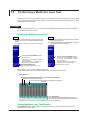
7.1
Creating New Projects
1
2
Procedure
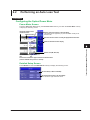
New Project Screen
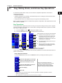
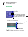
1. Press the Multi-Core Loss Test soft key.
3
2. Press the Master/Slave soft key to select Master.
3. Press the New Project soft key to display the following screen.
Complete
Press this soft key after you have configured the project, wavelength,
and offset settings. The loss test screen shown in the next section
appears.
If you enter a project name and specify at least one wavelength, this
key becomes available.
Project Name
To set the project name, follow the procedure in section 2.2.
4
5
Set the starting core number (1 to 9900).
Set the tape number type (Off, a-b(2), a-c(3), a-d(4), a-e(5), a-f(6),
a-g(7), a-h(8)).
Set the number of fibers or tapes (up to 100 fibers when Tape
no. Type is set to Off, up to 50 tapes when Tape no. Type is set
to a-b(2), ..., up to 12 tapes when Tape no. Type is set to a-h(8)).
Cancels the project settings.
The AQ1100 returns to the previous screen.
8
Set the offset (–9.900 to 9.900 dB).
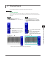
Loss Test Screen
Press the Complete soft key to display the following screen.
9
The selected core number is highlighted.
Skipped core numbers are dimmed.
Use the rotary knob and the arrow keys
to select a core number.
Set the list to show (Core List, List).
For list examples, see section 3.4.
10
11
Starts loss testing (see section 7.3)
App
Specify skipping.
Starts the transmission of project
information (see section 7.2)
Index
Saving Project Information
Press SETUP and then the File soft key to display the file save screen. Follow the procedure in
section 9.2 to save the project information that you configured.
IM AQ1100-01EN
7
Multicore Loss Testing (-SPM and -HPM suffix codes)
Set the wavelength.
The available settings vary depending on the model. For details, see
the explanation later in this section.
6
7-1
7.1 Creating New Projects
Explanation
You can create a new project. You can measure optical loss with models with -SPM or -HPM suffix
codes.
Creating a New Project
Only the master can create a new project. You can specify the following project information.
Project Name
You can set the name using up to 30 characters.
Starting Core Number
You can set the starting core number to a value within the following range.
1 to 9900
Tape Number Type
Off, a-b(2), a-c(3), a-d(4), a-e(5), a-f(6), a-g(7), a-h(8)
Number of Fibers or Tapes
You can set the number of fibers or tapes to a value within one of the following ranges.
Tape Number Type
Off
a-b(2)
a-c(3)
a-d(4)
a-e(5)
a-f(6)
a-g(7)
a-h(8)
Number of Fibers or Tapes
10 to 100 fibers
10 to 50 tapes
10 to 33 tapes
10 to 25 tapes
10 to 20 tapes
10 to 16 tapes
10 to 14 tapes
10 to 12 tapes
Measurement Light Wavelength
There are three instrument types, with the measurement light wavelengths listed below. Select a
wavelength from the available settings on the AQ1100 that you are using.
Model
AQ1100A
AQ1100B
AQ1100D
Measurement Light Wavelength
SM 1310 nm, SM 1550 nm
SM 1310 nm, SM 1550 nm, SM 1625 nm
GI 850 nm, GI 1300 nm, SM 1310 nm, SM 1550 nm
• The light for single mode (SM) optical fiber is emitted from optical port 2. The light for gradedindex (GI) multi-mode optical fiber is emitted from optical port 3. Firmly connect the optical fiber
to the port from which the light with the selected wavelength will be transmitted.
• You can specify up to three wavelengths in the AQ1100 setup screen.
• The AQ1100 cannot produce SM and GI wavelengths at the same time.
Offset
See “Explanation” in section 3.2.
Skipping
If you specify Skip for a core number that you don’t need to measure, its data will not be saved. By
setting which cores to skip beforehand, you can avoid accidentally saving unnecessary data.
Saving Project Information
You can save project information to a file. For the procedure for saving project information to a file, see
section 9.2. You can load saved files to both the master and the slave (see section 7.2).
7-2
IM AQ1100-01EN
7.2
Sharing Projects
1
2
The three different methods for sharing project information are listed below.
Procedure
Sending a Project
3
Connect one end of the communication fiber that you specified to the master’s light source port,
and connect the other end to the slave’s optical power measurement port. Then transfer the project
information.
Slave
1. Press the Multi-Core Loss Test soft key.
2. Press the Master/Slave soft key to select Slave. The
following menu appears.
4
Master
1. Press the Multi-Core Loss Test soft key.
2. Press the Master/Slave soft key to select Master.
3. Create a new project (see section 7.1), or load a
5
project file (see the next page). The following menu
appears.
6
7
soft key.
On the menu, “Receive Project from Master”
changes to “Abort.”
After reception finishes, “Abort” changes back
to “Receive Project from Master” and the
following screen appears.
Loss Test Screen
4. Press the Project Transmission START
soft key.
On the menu, “Project Transmission START”
changes to “Project Transmission STOP.”
After transmission finishes, “Project
Transmission STOP” changes back to “Project
Transmission START” and the following screen
appears.
Loss Test Screen
Multicore Loss Testing (-SPM and -HPM suffix codes)
3. Press the Receive Project from Master
8
9
10
11
App
Now the master and slave share the same project information.
IM AQ1100-01EN
Index
7-3
7.2 Sharing Projects
Loading a Project File
Load the same project file onto the master and the slave.
Press the Multi-Core Loss Test soft key and then the File soft key to display the following screen.
Set the drive to load from (internal memory,
USB memory)
Use the rotary knob and ENTER to
select a project information file.
Loads the file
The project information is loaded from the
selected file, and the loss test screen appears.
Restarting an Interrupted Loss Test
When the loss test for a shared project is interrupted, you can restart it where it left off, retaining the
results of the test so far.
The operation for restarting the test is the same for both the master and the slave.
Press the Multi-Core Loss Test soft key and then the Previous Project soft key to display the
following screen.
Display Example: Master
Loads the previous project
The lost test screen appears with the previous
lost test data retained.
7-4
IM AQ1100-01EN
7.2 Sharing Projects
1
Explanation
The master and slave must share the same project information. The methods for sharing project
information are listed below. Models with -SPM or -HPM suffix codes can share project information.
2
Sending a Project
You can send project information from the master to the slave.
First, you must specify a fiber for communicating the project information from the master to the slave.
Before you transfer the project information, connect one end of the communication fiber that you
specified to the master’s light source port, and connect the other end to the slave’s optical power
measurement port.
• Prepare the slave to receive the project information.
• After you have confirmed that the slave is ready to receive the information, send it from the master.
Loading a Project File
3
4
5
Load the same project file onto the master and the slave. Use a project file that you have saved to
internal or USB memory.
Restarting an Interrupted Loss Test
A multicore fiber loss test may be stopped before all the cores have been tested. When the test for a
shared project is interrupted, you can restart it where it left off, retaining the results of the test so far.
• You must be performing the loss test with the same project.
• If you reload a project file, the loss test data up to that point is deleted and cannot be recovered.
6
7
Multicore Loss Testing (-SPM and -HPM suffix codes)
8
9
10
11
App
Index
IM AQ1100-01EN
7-5
7.3
Performing a Multicore Loss Test
Connect one end of the communication fiber that you specified to the master’s light source port (optical
port 2), and connect the other end to the slave’s optical power measurement port (optical port 1). Then
perform the multicore loss test.
Procedure
After the settings in sections 7.1 to 7.2 have been completed, open the loss test screen, and perform
the multicore loss test procedure.
Executing a Multicore Loss Test
Slave
4. Connect to the light source port the optical fiber that
corresponds to the core number transmitted from the
master.
It may take time to receive the core number from the master.
Master
1. Connect the optical fiber under loss test to the optical
power measurement port.
2. Use the rotary knob and the arrow keys to select the
core number of the connected fiber.
5. Press the Loss Test START soft key.
3. Press the Loss Test START soft key.
The light turns on.
The core number is transmitted to the slave.
On the menu, “Loss Test START” changes to
“Loss Test STOP.”
After loss testing stops, “Loss Test STOP”
changes back to “Loss Test START.”
On the menu, “Loss Test START” changes to
“Loss Test STOP.”
After loss testing stops, “Loss Test STOP”
changes back to “Loss Test START.”
Optical Power Adjustment
Adjust as necessary (see section 7.4).
Specify skipping as necessary.
Follow steps 1 to 5 to perform a multicore loss test.
Check marks appear over core numbers whose loss tests have been completed.
Displayed List
Check mark indicating that the core’s loss test has been completed
Skipped core numbers are dimmed.
The core number that is undergoing loss testing is highlighted.
Core no.
Loss Test Results
Use the rotary knob and the arrow keys to select a
core number. The loss test results of the selected core
number are displayed.
Saving Multicore Loss Test Results
Press SETUP and then the File soft key to display the file save screen. Follow the procedure in
section 9.2 to save the data.
7-6
IM AQ1100-01EN
7.3 Performing a Multicore Loss Test
1
Explanation
Multicore loss testing is performed while information such as project, core number, loss test result, and
device information is transferred between the master and slave. Execute a multicore loss test in the
loss test screen after the settings in sections 7.1 to 7.2 have been completed.
You can measure optical loss with models with -SPM or -HPM suffix codes.
Displayed List
2
3
For list examples, see section 3.4.
Saving Multicore Loss Test Results
You can save multicore loss test results to a file. For the procedure for saving project information to a
file, see section 9.2.
4
5
6
7
Multicore Loss Testing (-SPM and -HPM suffix codes)
8
9
10
11
App
Index
IM AQ1100-01EN
7-7
7.4
Optical Power Adjustment
Procedure
Optical Power Adjustment
Use a short optical fiber to connect an AQ1100 light source port to an AQ1100 optical power
measurement port, and then perform optical power adjustment.
In the loss test screen (see section 7.3) of the slave, press the LS Power Adjust soft key to display
the following screen.
Starts optical power adjustment
When adjustment ends normally, the
AQ1100 returns to the previous screen.
Cancels optical power adjustment
The AQ1100 returns to the previous
screen.
Explanation
Optical Power Adjustment
Adjust the optical power of the light source as necessary.
When you execute optical power adjustment, the AQ1100 automatically identifies the optical power
level and adjusts itself accordingly. Perform optical power adjustment on the light source.
• Optical power adjustment begins when you press the Execute soft key. When it ends normally, the
AQ1100 returns to the previous screen. During adjustment, “Execute” changes to “Abort.” All soft
keys other than the Abort soft key are unavailable.
• Press the Abort soft key to stop optical power adjustment. “Abort” will change to “Execute.” The
adjustment value will return to the value that it was at before adjustment was executed.
• Connect a short optical fiber of a few meters or less in length. Make sure that the fiber is free from
dirt, scratches, bends, and other potential causes of optical degradation.
• The initial adjustment value is the factory default setting.
7-8
IM AQ1100-01EN
Chapter 8
8.1
IP Testing (Option)
Performing an IP Test
1
2
Procedure
Ping Test Setup Screen
Press the IP Test soft key to display the following screen.
3
Set the address to ping.
4
Set the frame length (32 to 1526 bytes)
Set the Tx Mode (Continue, Frames, Time)
Frames: 1 to 3600
Time: 1 to 3600 s
5
Set the measurement interval (100ms, 1s)
Starts pinging
6
Pinged address
Ping test results
The results of pinging the address appear here.
7
Explanation
IP testing is available on models with the /LAN option.
8
IP Testing (Option)
Pinging
Target Address
9
Specify the address that you want to ping.
Tx Frame
Set the conditions of the frame you will use for pinging.
10
• Frame Length
You can set the length of the frame that will be sent in a single ping to a value within the following
range.
32 to 1526 bytes
• Tx Mode
You can set the Tx mode to one of the following options. Depending on the Tx mode that you set,
you may set the number of frames and the time in the next menu.
Continue
Frames
Time
Frames are sent continuously, regardless of the set number of frames and time.
1 to 3600
1 to 3600 s
App
Index
Measurement Interval
Set the interval at which to measure the ping test items (see the next page) to one of the following
values.
100 ms, 1 s
IM AQ1100-01EN
11
8-1
8.1 Performing an IP Test
Pinging
Pinging is executed according to the Tx mode that you set.
• When it ends normally, the AQ1100 returns to the previous screen. During pinging, “PING Start”
changes to “PING Stop.” All soft keys other than the PING Stop soft key are unavailable.
• To stop pinging, press the PING Stop soft key. “PING Stop” will change to “PING Start.”
Ping Test Results
The ping test results are listed below. The pinged IP address and the ping test results are indicated
in the PING statistics table.
Sent frames, received frames, lost frames (reception failed), loss rate
8-2
IM AQ1100-01EN
Chapter 9
File Operation and Printing
9.1
Connecting a USB Storage Medium to the USB
Port
Use a portable USB storage medium. Connect it directly to the USB Type A port on the AQ1100.
Hot-plugging is supported: you can connect or disconnect the USB device at any time, regardless of
whether the AQ1100 is on or off. When the power is on, the AQ1100 automatically detects the USB
storage medium after it is connected.
1
2
3
4
5
Note
• Connect USB storage devices to the AQ1100 directly, not through a USB hub.
• Use a portable USB storage medium. Do not connect an incompatible USB storage medium.
• Do not connect and disconnect a USB device repetitively. Provide a 10-second interval between removal
and connection.
• Do not connect or disconnect a USB device during the time from when the AQ1100 is turned on until key
operation becomes available.
• You can use USB storage devices that comply with USB 1.1.
6
7
8
9
File Operation and Printing
10
11
App
Index
IM AQ1100-01EN
9-1
9.2
Saving and Loading Data
Procedure
File Operation Screen
Models with -SPM or -HPM Suffix Codes
Press the OPM LS or Auto Loss Test soft key, SETUP, and then the File soft key to display the
following screen (which is the same as the one for models with -PPM suffix codes).
Models with -PPM Suffix Codes
Press the OPM LS or PON Power Meter soft key, SETUP, and then the File soft key to display the
following screen.
Directory path
The number of folders and files in the selected directory
Set the action (Save, Load).
Set the file type.
Set the extension of the file type you want
to save or load. For details, see the
explanation later in this section.
Set the destination drive (internal
memory, USB memory).
Use the rotary knob and ENTER to
select the save destination or the file that
you want to load.
The file name candidate for the next save operation
This indication appears when you set the action to “Save.”
Set the file name (see the File Name
Setup screen in the next section).
Saves or loads the file
Whether “Save” or “Load” is displayed
depends on which option you choose for
the Action setting.
When Multicore Loss Testing Is Selected on Models with -SPM or -HPM Suffix
Codes
Press the Multi-Core Loss Test soft key, SETUP, and then the File soft key to display the following
screen.
Directory path
The number of folders and files in the selected directory
Set the destination drive (internal
memory, USB memory).
Use the rotary knob and ENTER to select
the file save destination.
Set the file name (see the File Name
Setup screen in the next section).
Saves the file
For the procedure to load files, see section
7.2.
The file name candidate for the next save operation
9-2
IM AQ1100-01EN
9.2 Saving and Loading Data
1
File Name Setup Screen
Set the file name format (No., Comment, Comment +
No., No. + Comment).
2
Set the ID number (0 to 9999).
Specify a comment (up to 30 characters).
To enter a comment, follow the procedure in section 2.2.
File Name
The file name that is produced by the above settings is
displayed.
3
Explanation
4
Action
Select “Save” or “Load.”
The types of files that you can save are listed below.
5
File Type
Set the extension depending on the type of file that you want to save or load.
6
Saving
The types of files that you can save are listed below.
.CSV
.LTS
1 Logging results are also saved to CSV files. Logging results are saved in the file save screen that appears
after logging stops (see section 3.3).
2 “Screen Image Save” may appear on the menu. Press this soft key to save the image displayed by “Screen
Image Save” to the root directory of the internal memory with the file name SystemInfo.BMP.
8
9
10
11
Loading
The types of files that you can load are listed below.
.CSV
.LTS
.CFG
7
File Operation and Printing
.CFG
.BMP
.PNG
.JPG
A CSV format measurement data file1
The measurement data (including measurement conditions such as the wavelength and offset) for the
specified core and tape numbers is saved.
• Optical power meter measurement data (see section 3.4)
• PON power meter measurement data (see section 4.3)
• Loss test results (see section 6.2)
• Loop-back loss test results (see section 6.3)
• Multicore loss test results (see section 7.3), project information (see section 7.1)
File containing optical power meter measurement conditions, PON power meter measurement
conditions, and optical output conditions
System setup data file
BMP screen image data file
When you select “Save,” the screen image from
PNG screen image data file
immediately before you switched to the file
operation screen is saved.2
JPG screen image data file
For details, see “Saving.”
App
Drive to Save To
You can set the destination drive to one of the following options.
Internal memory
USB memory
IM AQ1100-01EN
Index
The AQ1100 internal memory
The USB storage medium connected to the USB Type A port on the AQ1100.
9-3
9.2 Saving and Loading Data
File Name
File Name Format
You can set the file name format to one of the following options. For all formats, the maximum
number of characters is 36.
No., Comment, Comment + No., No. + Comment
Comment
ID No.
Extension
Up to 30 characters
Four characters
The range is 0 to 9999. Four characters are used in the file name. For example, if you set the
number to “1,” “0001” will be used in the file name.
Four characters, including the period.
If the total length of the file name exceeds 36 characters, the last characters in the comment are
removed until the file name is 36 characters long.
String and Character Types That Can Be Used in File and Folder Names
There are limitations on the types of strings and characters that you can use in file and folder
names.
• The following character strings cannot be used as file or folder names due to MS-DOS
limitations.
AUX, CON, PRN, NUL, CLOCK, CLOCK$, LPT0, LPT1, LPT2, LPT3, LPT4, LPT5, LPT6, LPT7,
LPT8, LPT9, COM0, COM1, COM2, COM3, COM4, COM5, COM6, COM7, COM8, COM9
• The following types of characters can be used: 0 to 9, A to Z, a to z, _, –, =, (, ), {, }, [, ], #, $, %, &,
~, !, `,and @.
@ cannot be entered consecutively.
• Make sure that the full file path (absolute path from the root folder) is less than or equal to
200 characters in length. If it exceeds 200 characters, an error occurs when you perform a file
operation (such as saving, copying, renaming, or creating a folder).
Full file path:
When an operation is being performed on a folder, the full path is up to the name of the
folder.
When an operation is being performed on a file, the full path is up to the name of the file.
About the File Operation Screen
Depending on the model and the selected feature, the operations for opening the file operation screen
and the screens that appear vary.
• When multicore loss testing is selected on models with -SPM or -HPM suffix codes, a screen for
saving the project information and core loss test results in CSV format appears.
• For information about loading files when multicore loss testing is selected on models with -SPM or
-HPM suffix codes, see section 7.2. Select a file that contains project information and multicore loss
test results and load it.
9-4
IM AQ1100-01EN
9.3
Deleting and Copying Files
1
2
Procedure
File Operation Screen
Models with -SPM or -HPM Suffix Codes
3
Press the OPM LS or Auto Loss Test soft key, SETUP, and then the File soft key to display the
following screen (which is the same as the one for models with -PPM suffix codes).
Models with -PPM Suffix Codes
Press the OPM LS or PON Power Meter soft key, SETUP, and then the File soft key to display the
following screen.
Directory path
The number of folders and files in the selected directory
4
5
Set the action (Delete, Copy).
Set the file type.
Set the extension of the file type you want
to delete or copy.
Set the destination drive
(internal memory, USB memory).
6
7
Selecting All Files
Use the rotary knob and ENTER to select
the files you want to delete or copy.
Selected files are indicated with this
mark: . To deselect a file, press ENTER
again.
Deletes the selected files or displays
a screen for selecting the copy
destination.
Whether “Delete” or “Dest. Folder” is
displayed depends on which option you
choose for the Action setting.
8
9
File Operation and Printing
When you press the Dest. Folder soft key,
a screen for selecting the copy destination
folder appears.
In that screen, select the destination folder
and press the Execute soft key to copy the
files.
10
11
App
Index
IM AQ1100-01EN
9-5
9.3 Deleting and Copying Files
Explanation
Action
Select “Delete” or “Copy.”
File Type
The files of the type that you selected appear in the File List screen.
• For details about file types, see “Explanation” in section 9.2.
• To display all the files in the current directory, set the file type to “*.*”.
Drive to Save To
See “Explanation” in section 9.2.
Selecting All Files
All the files in the current directory will be deleted or copied.
• When you press the All Select soft key, “All Select” changes to “All Deselect.”
• When you press the All Deselect soft key, “All Deselect” changes to “All Select.” All the files in the
current directory are deselected.
Deleting
The selected files are deleted.
Setting the Copy Destination and Copying
After selecting the files to copy, set the destination folder and copy the files.
About the File Operation Screen
Depending on the model and the selected feature, the operations for opening the file operation screen
and the screens that appear vary.
On models with -SPM or -HPM suffix codes, you cannot delete or copy files when multicore loss
testing is selected.
Note
Using the mini B USB port on the AQ1100, you can send the files and folders in the AQ1100 internal memory
to a PC. To do this, set the AQ1100 mini B USB port function to Storage (see section 10.1). When the PC
accesses the AQ1100 and downloads the files, the download speed depends on the performance of the PC.
9-6
IM AQ1100-01EN
9.4
Changing File Names
1
2
Procedure
File Operation Screen
Models with -SPM or -HPM Suffix Codes
3
Press the OPM LS or Auto Loss Test soft key, SETUP, and then the File soft key to display the
following screen (which is the same as the one for models with -PPM suffix codes).
Models with -PPM Suffix Codes
Press the OPM LS or PON Power Meter soft key, SETUP, and then the File soft key to display the
following screen.
Directory path
The number of folders and files in the selected directory
4
5
Set the action (Rename).
Set the file type.
Set the extension of the file type of the file
whose name you want to change.
Set the destination drive (internal
memory, USB memory).
Use the rotary knob and ENTER to select
the file whose name you want to change.
Selected files are indicated with this
mark: . To deselect a file, press ENTER
again.
6
7
Enter a new file name.
The character input dialog box appears. To
set the file name, follow the procedure in
section 2.2. Enter the extension as well.
After you have entered the file name, press
the Commit soft key in the character input
dialog box to change the file name to the
name that you entered.
8
9
File Operation and Printing
10
11
App
Index
IM AQ1100-01EN
9-7
9.4 Changing File Names
Explanation
Action
Select “Rename.”
File Type
The files of the type that you selected appear in the File List screen.
• For details about file types, see “Explanation” in section 9.2.
• To display all the files in the current directory, set the file type to “*.*”.
Drive to Save To
See “Explanation” in section 9.2.
Entering a File Name
Enter a file name into the character input dialog box that appears. Follow the procedure in section 2.2.
• Use the character input dialog box to enter the extension as well.
• When you press the Commit soft key in the character input dialog box, the file name changes to the
name that you entered.
About the File Operation Screen
Depending on the model and the selected feature, the operations for opening the file operation screen
and the screens that appear vary.
On models with -SPM or -HPM suffix codes, you cannot change file names when multicore loss testing
is selected.
9-8
IM AQ1100-01EN
9.5
Creating Folders
1
2
Procedure
File Operation Screen
Models with -SPM or -HPM Suffix Codes
3
Press the OPM LS or Auto Loss Test soft key, SETUP, and then the File soft key to display the
following screen (which is the same as the one for models with -PPM suffix codes).
Models with -PPM Suffix Codes
Press the OPM LS or PON Power Meter soft key, SETUP, and then the File soft key to display the
following screen.
Directory path
The number of folders and files in the selected directory
4
5
Set the action (Make Folder).
6
Set the destination drive (internal
memory, USB memory).
Use the rotary knob and ENTER to select
the directory you want to create the folder
in.
7
Create a folder.
The character input dialog box appears.
To set the folder name, follow the
procedure in section 2.2.
After you have entered the folder name,
press the Commit soft key in the character
input dialog box to create the folder.
9
File Operation and Printing
Explanation
Action
10
Drive to Save To
11
Select “Make Folder.”
See “Explanation” in section 9.2.
Entering a Folder Name
Enter a folder name into the character input dialog box that appears. You can use up to 20 characters.
Follow the procedure in section 2.2. When you press the Commit soft key in the character input dialog
box, a folder with the name that you specified is created.
App
Index
About the File Operation Screen
Depending on the model and the selected feature, the operations for opening the file operation screen
and the screens that appear vary.
On models with -SPM or -HPM suffix codes, you cannot create folders when multicore loss testing is
selected.
IM AQ1100-01EN
8
9-9
9.6
Deleting and Copying Folders
Procedure
File Operation Screen
Models with -SPM or -HPM Suffix Codes
Press the OPM LS or Auto Loss Test soft key, SETUP, and then the File soft key to display the
following screen (which is the same as the one for models with -PPM suffix codes).
Models with -PPM Suffix Codes
Press the OPM LS or PON Power Meter soft key, SETUP, and then the File soft key to display the
following screen.
Directory path
The number of folders and files in the selected directory
Set the action (DeleteFolder, Copy
Folder).
Set the destination drive (internal
memory, USB memory).
Use the rotary knob and ENTER to select
the folder you want to delete or copy.
Deletes the selected files or displays a
screen for selecting the copy destination.
Whether “Delete” or “Dest. Folder” is
displayed depends on which option you
choose for the Action setting.
When you press the Dest. Folder soft key,
a screen for selecting the copy destination
folder appears.
Make sure that the copy destination and
source drives are different (see the
explanation later in this section).
In the screen that appears, select the
destination folder and press the Execute
soft key to copy the files.
9-10
IM AQ1100-01EN
9.6 Deleting and Copying Folders
1
Explanation
Action
Select “DeleteFolder” or “Copy Folder.”
2
Drive to Save To
See “Explanation” in section 9.2.
3
Deleting
The selected folders are deleted.
4
Setting the Copy Destination and Copying
After selecting the folders to copy, set the destination folder and copy the selected folders to it.
You cannot copy from the internal memory to the internal memory or from the USB memory to the USB
memory. Copy folders from the internal memory to the USB memory or from the USB memory to the
internal memory.
About the File Operation Screen
Depending on the model and the selected feature, the operations for opening the file operation screen
and the screens that appear vary.
On models with -SPM or -HPM suffix codes, you cannot delete or copy folders when multicore loss
testing is selected.
5
6
7
Note
• You may not be able to copy or delete the selected folder if it contains many levels of folders.
• Using the mini B USB port on the AQ1100, you can send the files and folders in the AQ1100 internal
memory to a PC. To do this, set the AQ1100 mini B USB port function to Storage (see section 10.1). When
the PC accesses the AQ1100 and downloads the files, the download speed depends on the performance
of the PC.
8
9
File Operation and Printing
10
11
App
Index
IM AQ1100-01EN
9-11
9.7
Initializing the Internal Memory
Procedure
File Operation Screen
Models with -SPM or -HPM Suffix Codes
Press the OPM LS or Auto Loss Test soft key, SETUP, and then the File soft key to display the
following screen (which is the same as the one for models with -PPM suffix codes).
Models with -PPM Suffix Codes
Press the OPM LS or PON Power Meter soft key, SETUP, and then the File soft key to display the
following screen.
Set the action (Format).
Formats the internal memory
Explanation
Action
Select “Format.”
Formatting
The internal memory is initialized. All the data in the internal memory is deleted. Before you initialize
the internal memory, backup the data as necessary.
Note
Using the mini B USB port on the AQ1100, you can send the files and folders in the AQ1100 internal memory
to a PC. To do this, set the AQ1100 mini B USB port function to Storage (see section 10.1). When the PC
accesses the AQ1100 and downloads the files, the download speed depends on the performance of the PC.
9-12
IM AQ1100-01EN
9.8
Printing
1
2
Procedure
File Operation Screen
Models with -SPM or -HPM Suffix Codes
Press the OPM LS or Auto Loss Test soft key, SETUP, and then the File soft key to display the
following screen (which is the same as the one for models with -PPM suffix codes).
Models with -PPM Suffix Codes
Press the OPM LS or PON Power Meter soft key, SETUP, and then the File soft key to display the
following screen.
4
5
Set the action (Print).
Configure printing.
Specify the maker and the print color.
3
6
7
Starts printing
8
Explanation
Action
Select “Print.”
9
File Operation and Printing
Print Setup
Specify the maker of the printer connected to the AQ1100 and the print color.
• Connect the printer to the USB Type A port on the AQ1100.
• You can use printers that comply with USB Printer Class Ver 1.1.
10
Printing
11
An image of the screen is printed.
About the File Operation Screen
Depending on the model and the selected feature, the operations for opening the file operation screen
and the screens that appear vary.
On models with -SPM or -HPM suffix codes, you cannot print when multicore loss testing is selected.
Index
Note
• Do not connect incompatible printers.
• For USB printers that have been tested for compatibility, contact your nearest YOKOGAWA dealer.
IM AQ1100-01EN
App
9-13
Chapter 10 Other Operations
10.1 Configuring the Language, Beep, Start Menu,
USB Function, and Screen Color
1
Procedure
2
System Setup Screen
Press SETUP to display the following menu.
3
Set the display language.
The options that appear vary depending on the language specification.
Turns the beep on and off
4
Set the start menu (Top Menu, Last Function).
Set the USB function (Storage, Control I/O)
Set the screen colors (Color, B&W)
5
6
Explanation
7
Display Language
Set the language to display on the AQ1100 screen. The options that appear vary depending on the
product’s language specification.
8
Turning the Beep On and Off
You can make the AQ1100 beep whenever an operation error occurs or an error message is displayed.
On
Off
The AQ1100 beeps.
The AQ1100 does not beep.
Start Menu
10
You can choose which screen will appear first when you turn on the AQ1100.
The menu that appears when you press the MENU key on the front panel.
The menu of the last function that you were using before the AQ1100 was turned off appears.
The first menu that appears is one of the menus that appears after you press a soft key in the
Top Menu.
USB Function
You can set the function of the mini B USB port on the AQ1100.
Storage
Control I/O
11
App
You can access the AQ1100 internal memory from a PC and load and save data.
You can use communication commands to control the AQ1100 from a PC.
Index
Screen Color
Set the screen display colors.
Color, B&W
IM AQ1100-01EN
Other Operations
Top Menu
Last Function
9
10-1
10.2 Configuring Power Save Settings
Procedure
Power Save Screen
1. Press SETUP.
2. Using the rotary knob and ENTER, select Power Save to display the following screen.
Using AC power
Configure the auto power off feature (Off, AutoPowerOff 1m,
AutoPowerOff 5m, AutoPowerOff 10m, AutoPowerOff 30m).
Set the LCD brightness (Bright, Normal, Power save, Off)
Using battery
Configure the auto power off feature (Off, AutoPowerOff 1m,
AutoPowerOff 5m, AutoPowerOff 10m, AutoPowerOff 30m).
Set the LCD brightness (Bright, Normal, Power save, Off)
Set the screen save feature.
Explanation
To reduce power consumption, you can set separate power save settings for when the AQ1100 is
using an AC adapter and for when it is using a battery.
Auto Power Off
When the AQ1100 is on, it can turn itself off automatically after it has not been used for awhile.
Off
AutoPowerOff 1m
AutoPowerOff 5m
AutoPowerOff 10m
AutoPowerOff 30m
The power does not turn off automatically.
The power turns off automatically after one minute.
The power turns off automatically after 5 minutes.
The power turns off automatically after 10 minutes.
The power turns off automatically after 30 minutes.
LCD Brightness
You can set the LCD brightness.
Bright
Normal
Power save
Off
The screen is bright. Choose this setting when you are in a bright area. Because this setting
uses a great deal of power, pay close attention to the remaining battery power when you are
using a battery.
Normal brightness.
The screen is less bright than it is when you select Normal. You can view the screen at this
brightness when you are in a dark area. You can use the battery longer than you can when you
select Bright.
The LCD backlight is turned off. When you are viewing the screen beneath the sun or in
another bright area, the screen will be difficult to view even if you select Bright. In this kind of
situation, you can make the screen easier to view by selecting Off. You can use the battery
even longer than you can when you select Power save.
Screen Save
When the AQ1100 is on, it can turn its display off automatically after it has not been used for 15
seconds.
10-2
IM AQ1100-01EN
10.3 Resetting the AQ1100 to Its Factory Default
Settings
1
Procedure
2
Initialization Screen
1. Press SETUP.
3
2. Using the rotary knob and ENTER, select Default to display the following screen.
Initializes the measurement settings
All measurement settings are returned to their factory defaults.
4
Initializes all settings
All settings are returned to their factory defaults, and the internal memory is
formatted.
5
Explanation
You can reset the AQ1100 to its factory default settings.
6
Initializing the Measurement Settings
All the settings are reset to their factory defaults, but the internal memory is not initialized.
7
Initializing All Settings
All the settings are reset to their factory defaults, and the internal memory is initialized. All the data
in the internal memory is deleted. Before you initialize the internal memory, backup the data as
necessary.
8
Note
Using the mini B USB port on the AQ1100, you can send the files and folders in the AQ1100 internal memory
to a PC. To do this, set the AQ1100 mini B USB port function to Storage (see section 10.1). When the PC
accesses the AQ1100 and downloads the files, the download speed depends on the performance of the PC.
9
10
Other Operations
11
App
Index
IM AQ1100-01EN
10-3
10.4 Configuring Network Settings (Option)
Procedure
Network Setup Screen
1. Press SETUP.
2. Using the rotary knob and ENTER, select Network Setup to display the following screen.
Enables or disables the network setup
Set the user name and password.
To set the user name and password, follow the procedure in section 2.2.
Set the timeout value.
Configure the TCP/IP settings.
Note
You must restart the AQ1100 after you have changed the network settings. Before you restart the AQ1100,
the settings from before you changed the settings are used.
Explanation
IP testing is available on models with the /LAN option.
For details about the network that you intend to connect the AQ1100 to, contact your network
administrator.
Enabling or Disabling the Network Setup
After you have set the user name, password, timeout value, and TCP/IP parameters, select Valid and
restart the AQ1100 to use the network connection.
Valid
Invalid
The AQ1100 can communicate over the network.
The AQ1100 cannot communicate over the network.
If Valid is selected and the AQ1100 is not connected to a network, it will require more time to start.
User Name and Password
Set the user name and password to use for user authentication when the AQ1100 is accessed by a
PC.
User Name
You can use up to 15 characters. The default setting is “anonymous.”
Password
You can use up to 15 characters.
Note
• The AQ1100 terminates the connection if there is an error in the user authentication process.
• You do not need to enter a password when the user name is set to “anonymous.”
10-4
IM AQ1100-01EN
10.4 Configuring Network Settings (Option)
1
Timeout Value
The connection to the network is automatically disconnected if there is no access to the AQ1100 for
the specified time.
Range: 1 to 3600 s or Infinite
The AQ1100 will not time out if you set the timeout value to Infinite. If the AQ1100 is connected to a
network and the connection between the AQ1100 and another device is broken abnormally due to an
external cause, the AQ1100 will remain connected to the network until the power is turned off. To avoid
this kind of situation, we recommend that you set a finite timeout value.
2
3
TCP/IP
DHCP
If you are connecting the AQ1100 to a network with a DHCP server and you want to use the server,
set DHCP to “On.”
On
Off
The IP address, subnet mask, and gateway information is assigned automatically.
You must enter the IP address, netmask, and gateway information.
• Ask your network administrator whether or not DHCP is available.
• When DHCP is set to On, the information can change whenever you restart the AQ1100 or
enable or disable the network setup as described in the previous section. Check the information
when you access the AQ1100 from a PC.
4
5
6
IP Address
You can set the IP address assigned to the AQ1100. The IP address is an ID that is assigned to
each device on a network such as the Internet or an intranet. Obtain an IP address from your
network administrator. In a network that supports DHCP, this parameter is set automatically when
DHCP is set to On.
Subnet Mask
You can set the mask value used to determine the subnet network address from the IP address.
Networks such as the Internet are often divided up into smaller networks called subnetworks. The
subnet mask is a value that specifies the number of bits of the IP address that are used to identify
the network address. Consult your network administrator for the subnet mask value. In a network
that supports DHCP, this parameter is set automatically when DHCP is set to On.
You can set the IP address of the default gateway (which is a gateway used to communicate with
other networks). The default gateway handles data exchange between multiple networks so that
data transmission proceeds smoothly. Consult your network administrator for the default gateway
value. In a network that supports DHCP, this parameter is set automatically when DHCP is set to
On.
8
9
10
Other Operations
Gateway
7
11
App
Index
IM AQ1100-01EN
10-5
Chapter 11 Troubleshooting, Maintenance, and Inspection
11.1 If a Problem Occurs
1
2
Dealing with Unusual Circumstances
• If a message appears on the screen, see the following pages for reference.
• If servicing is necessary or the AQ1100 does not operate properly even after you have attempted to
deal with the problem according to the instructions in this section, contact your nearest YOKOGAWA
dealer.
Symptom
Even when the power is
on, nothing appears on
the screen.
The display disappears
after time passes.
The screen is dark.
The power turns off
automatically while the
AQ1100 is being used.
The battery pack cannot
be charged.
The power turns off
automatically while the
AQ1100 is starting.
Solution
Reference
If you are using an AC adapter, make sure that the plug is connected firmly to the outlet,
—1
the power cord is connected firmly to the AC adapter, and the AC adapter’s DC plug is
connected firmly to the AQ1100.
If you are using a battery pack, make sure that it is attached firmly.
—1
Charge the battery pack, and make sure that the ON lamp is illuminated.
11.7
The LCD turns black at high temperatures. At low temperatures, its display speed becomes
—1
slower. Make sure that the temperature of the area where you are using the AQ1100 is
within the operating temperature range.
The AQ1100 turns off automatically when its battery is low. Check the remaining battery
11.7
power.
If you have specified a time for the Power Save setting, the AQ1100 will turn off
10.2
automatically if no operations have been performed for the specified time. Check the
settings.
The screen is dark when the LCD Brightness setting is set to “Power save.” Check the
10.2
settings.
The LCD may be worn out. Servicing is required.
11.11
When the temperature of the AQ1100 or its battery pack is high, the AQ1100 lowers the
—1
LCD brightness automatically to prevent damage. Make sure that the temperature of the
area where you are using the AQ1100 is within the operating temperature range.
The AQ1100 turns off automatically when it detects an error. A warning message will
11.22
appear when this happens. Read the message. Fix the problem indicated in the message,
and then turn on the AQ1100.
The battery pack temperature may be too low or too high. Make sure that the temperature
—1
of the area where you are using the AQ1100 is within the operating temperature range.
Remove the battery pack from the AQ1100 and let it sit for awhile in a room temperature
environment.
The battery pack may be reaching the end of its life expectancy. Replace it with a new
11.11
one.
You may have accidentally pressed the power switch twice.
—
3
4
5
6
7
8
9
10
1 See the operation guide, IM AQ1100-02EN.
2 When it is likely that the usage limitations of the AQ1100 will be exceeded, the AQ1100 will display a
warning message and turn off automatically to prevent damage. For the conditions under which messages
appear, see section 11.2.
11
Troubleshooting, Maintenance, and Inspection
App
Index
IM AQ1100-01EN
11-1
11.2 Error Messages
Error Messages
Messages may appear on the screen while you are using the AQ1100. This section explains the
meanings of the error messages and how to respond to them. You can display the error messages in
English or Japanese (see section 10.1). If servicing is necessary to solve the problem indicated by a
message, contact your nearest YOKOGAWA dealer.
Other communication-related error messages may also appear. These error messages are described
in the Communication Interface User’s Manual, IM AQ1100-17EN.
Error in Execution
Code
20
24
29
33
64
Message
Network Option is not installed.
One or more conditions in this file are not supported by this product.
In remote control mode, all keys are locked except F1 key. Please hit F1 key to exit the remote control mode.
File operation is cancelled.
Failed to adjust LS power. Please check whether the patch fiber cable is properly connected between LS port and
OPM port.
65
Project Information doesn’t match between Master and Slave.
66
The project sent from master includes an unsuitable wavelength.
503
The measurement cannot be started during the file operation. Please either interrupt the file operation or wait until
the end of the file operation.
505
Hardware failed, and needs to be repaired. Please contact Yokogawa’s representatives.
506
Hardware failed, and needs to be repaired. Please contact Yokogawa’s representatives.
507
Hardware failed, and needs to be repaired. Please contact Yokogawa’s representatives.
508
Hardware failed, and needs to be repaired. Please contact Yokogawa’s representatives.
509
Hardware failed, and needs to be repaired. Please contact Yokogawa’s representatives.
512
ZERO SET ERROR
513
ZERO SET ERROR
514
Exceeding limit. It may cause damage of the instrument. Please disconnect the plug.
515
ZERO SET ERROR
601
Cannot save onto the media. This media is for read-only.
602, 603
Can not recognize file system. - Internal memory:Contact Yokogawa’s representatives. - USB memory:Try the other
media or format again with FAT.
604
Storage media has been disconnected while the media is being accessed.
605
Same file name or folder name exists.
606, 607
Can not recognize file system. - Internal memory:Contact Yokogawa’s representatives. - USB memory:Try the other
media or format again with FAT.
608
Invalid file name or folder name
609
Invalid file format
610, 611
Can not recognize file system. - Internal memory:Contact Yokogawa’s representatives. - USB memory:Try the other
media or format again with FAT.
612
Invalid path name
613
Can not recognize file system. - Internal memory:Contact Yokogawa’s representatives. - USB memory:Try the other
media or format again with FAT.
614
Unknown file or folder
615
Can not recognize file system. - Internal memory:Contact Yokogawa’s representatives. - USB memory:Try the other
media or format again with FAT.
616
Cannot save onto the media. This media is for read-only.
617 to 619 Can not recognize file system. - Internal memory:Contact Yokogawa’s representatives. - USB memory:Try the other
media or format again with FAT.
620
Free space is not enough
621
Can not recognize file system. - Internal memory:Contact Yokogawa’s representatives. - USB memory:Try the other
media or format again with FAT.
622
Unknown folder
623
Folder is not empty.
624 to 628 Can not recognize file system. - Internal memory:Contact Yokogawa’s representatives. - USB memory:Try the other
media or format again with FAT.
11-2
IM AQ1100-01EN
11.2 Error Messages
IM AQ1100-01EN
11-3
1
2
3
4
5
6
7
8
9
10
11
Troubleshooting, Maintenance, and Inspection
Code
Message
629
Writing to USB memory is not allowed.
630 to 633 Can not recognize file system. - Internal memory:Contact Yokogawa’s representatives. - USB memory:Try the other
media or format again with FAT.
634
Folder cannot be deleted. Please confirm the following.
- Media is correctly installed.
- Media is formatted.
- Media is not read-only.
635
Folder cannot be deleted. The path name or the file name is too long.
636
Folder cannot be deleted. The hierarchy below the specified folder is too deep.
637
Folder cannot be deleted. The path name is invalid.
638
Folder cannot be deleted. It failed in the deletion of the file. Please confirm the following.
- Media is correctly installed.
- Media is formatted.
- Media is not read-only.
639
Folder cannot be copied. Please confirm the following.
- Media is correctly installed.
- Media is formatted.
- Media is not read-only.
640
Folder cannot be copied. The path name or the file name is too long.
641
Folder cannot be copied. The hierarchy below the specified folder is too deep.
642
Failed to copy the folder. The path name is invalid.
643
Folder cannot be copied. It failed in the creation of the destination folder. Please confirm the following.
- Media is correctly installed.
- Media is formatted.
- Media is not read-only.
644
Folder cannot be copied. It failed in the creation of the destination file. Please confirm the following.
- Media is correctly installed.
- Media is formatted.
- Media is not read-only.
645
The path name is too long.
646
USB memory can not be recognized
647
Can not make file or folder in this folder.
690
Cannot save the measurement data. Please confirm the following.
- Media is correctly installed.
- Media is formatted.
- Media is not read-only.
691
There is **** files in the destination folder. Please use other folder.
692
Media is full. Please install new media.
693
Cannot make a folder. Please change the folder name.
694
Cannot open the file. Please confirm the following.
- Media is correctly inserted.Media is not changed.
695
One or more conditions in this file cannot be restored. The instrument automatically determines those conditions.
696
Folder cannot be deleted. Please confirm the following.
-There is no file or folder in this folder.
697
Folder can’t be copied. The destination folder is a subfolder of the source folder.
698
Folder can not be copied. Please confirm the following.
-There is no file or folder in this folder.
- Media is correctly inserted.
- Media is formatted.
- Media is not read-only.
700
Failed to open the file.
701
Failed to close the file.
702
Failed to read the file.
703
Irregular file format.
704
Failed to write the file.
707
One or more measurement conditions are not specified. Please confirm the measurement conditions.
708
Cannot be saved. This data is not taken with this instrument.
710
File cannot be retrieved. Invalid wavelength.
717
Duplicate file name.
718
File is damaged. Check the file.
719
File name too long. Maximum length is 36 letters.
720
File is now being accessed. Execute after access is released.
App
Index
11.2 Error Messages
Code
721
752
754
755
756
757
758
760
761
800
814
817
818
854
900
902
903
904
906
909
910
913
914
917
918
921
922
925
11-4
Message
Cannot load this file. Invalid file format or this firmware version is old.
Print Error. Printer cannot be found.
USB printer error Perform the power cycle.
USB printer is offline.
No paper (USB printer)
USB printer cannot be found. Perform the power cycle.
The printer is out of order, and needs to be repaired. Please contact Yokogawa’s representatives.
Cannot execute it while printing.
This operation is not excuted while light is emitting. Stop emitting the light then excute the operation.
This function is not supported.
Failed network initialize. Please confirm network connection and setting.
Test Error occurred.
Test succeeded.
In USB Storage mode, all keys are locked. Please disconnect the USB Cable.
Backup data is damaged. this instrument starts up with the factory setting.
Battery is low Please power it off, and charge the battery or replace the battery. Or, please use the AC power supply.
Backup battery failed, and needs to be repaired. Please contact Yokogawa’s representatives.
Hardware failed, and needs to be repaired. Please contact Yokogawa’s representatives.
Battery is low. The instrument will be powered off in 10 sec.
The temperature inside the instrument is too high. The instrument may be damaged if it is kept using in this
condition. The instrument will be powered off in 10 sec. Please do not power it on till the battery is cooled down.
The temperature inside the instrument is too low. The instrument may be damaged if it is kept using in this condition.
The instrument will be powered off in 10 sec. Please do not power it on till the battery is cooled down.
Battery is low. The instrument may be damaged if it is kept using in this condition. The instrument will be powered off
in 10 sec. Please use AC adapter.
Errors in the battery or in the charging circuit. The instrument may be damaged if it is kept using in this condition.
The instrument will be powered off in 10 sec. Please remove the battery and use AC adapter.
The temperature inside the instrument is increasing. Please stop measuring, and wait for a while.
The temperature inside the instrument is too high. The measurement was aborted. Please power it off.
There is incoming light. Or, optical module may be damaged.
Incorrect date and time setting. Set the correct date and time.
Please use AC adapter.
IM AQ1100-01EN
11.3 Viewing the Product Information
1
Procedure
2
Product Information Screen
Press SETUP and then the Product Info. soft key to display the following screen.
3
Saves a screen image
4
5
6
7
Explanation
The following information about the AQ1100 is displayed.
Model Name, Serial Number, Suffix Code, Mac Address, Version Information, etc.
8
Executing Screen Image Save
When you execute Screen Image Save, an image of the screen is saved to SystemInfo.BMP in the root directory of
the internal memory.
9
10
11
Troubleshooting, Maintenance, and Inspection
App
Index
IM AQ1100-01EN
11-5
11.4 Performing a Self Test
Procedure
System Setup Menu
Press SETUP to display the following menu.
Executes a self test
Explanation
The AQ1100 checks the operation of the:
• Internal memory.
• RTC (real time clock) battery.
If the results of the self test are normal, “Success” appears. If an error occurs, “Fail” appears.
When an Error Occurs during a Self Test
If an error occurs, contact your nearest YOKOGAWA dealer.
11-6
IM AQ1100-01EN
11.5 Updating the Firmware
1
Procedure
2
Version Up Screen
Press SETUP and then the Version Up soft key to display the following screen.
3
4
Select the drive that contains the
firmware update file (internal memory,
USB memory).
Use the rotary knob and ENTER to select
the firmware update file.
5
Executes the firmware update
6
Explanation
To update the firmware, select a firmware update file (.YMC extension).
• You can change file names, except for the extension, as necessary. For instructions on how to
change the file name, see section 9.4.
• When the firmware update ends successfully, “Updating of the main program completed” appears,
and the AQ1100 restarts automatically.
• When the firmware update fails, “Updating of the main program failed” appears. Make sure that
there are no problems with the firmware update file.
7
8
9
10
11
Troubleshooting, Maintenance, and Inspection
App
Index
IM AQ1100-01EN
11-7
11.6 Performing a Mechanical Inspection and
Checking Operations
Mechanical Inspection
WARNING
Make sure that the power is off while you are inspecting the AQ1100.
CAUTION
• If foreign objects are stuck in the connectors, malfunction and damage may occur.
• The AQ1100 may not operate properly if its connectors are loose.
Make sure that:
• There is no external damage or deformation on the outside of the AQ1100.
• There are no switches, connectors, or other components that are loose.
• All switches and moving parts can be operated smoothly.
If there are any problems, contact your nearest YOKOGAWA dealer.
Checking Operations
Turn on the AQ1100, perform the typical operations, and make sure that the AQ1100 performs
normally.
11-8
IM AQ1100-01EN
11.7 Replacing the Battery Pack
1
Handling Precautions
Failure to comply with the precautions below could lead to damage to the instrument, injury, or death.
WARNING
3
Prohibitions against Actions That Cause Leaking, Heating, Ignition, and Explosion
• Do not charge the battery pack or leave it in a location that is exposed to direct sunlight,
such as on a car dashboard or by a window, or in a location that is subject to high
temperatures, such as in a car parked under the scorching sun.
• Do not throw the battery pack into fire or heat it.
• Do not expose the battery pack to strong mechanical shock.
• Do not allow the battery pack to be covered in water or other liquids.
• Do not disassemble or modify the battery pack.
• Do not short the positive and negative battery pack terminals. Also, do not move the battery
or store it with metal items such as necklaces, hair pins, coins, or keys.
• Do not place combustible material on top of the battery pack or cover it with anything other
than its case while it is providing electricity or being charged.
• Leakage from the battery pack can cause blindness if it comes into contact with your eyes.
If you get leakage from the battery in your eyes, do not rub them; clean them thoroughly
with clean water and then see a doctor immediately.
• Do not use or charge battery packs with the AQ1100 that are not made by YOKOGAWA.
• When you attach the battery pack to the AQ1100, attach it properly.
5
6
7
9
Prohibition against Use under Abnormal Conditions
If you notice that the battery pack is leaking, smells strange, is becoming hot, has changed
color or shape, or exhibits some other abnormality, stop charging or using it, and turn off the
power. If the battery pack is leaking, move it away from sources of fire.
10
11
Troubleshooting, Maintenance, and Inspection
Changing the Battery Pack
• To prevent electric shock, turn the AQ1100 off, and disconnect the AC adapter power
supply from it.
• When you remove the battery pack cover, do not do so with the back of the AQ1100 facing
down. Also, after you attach the battery pack, be sure to close the battery cover completely.
Otherwise, the battery pack may fall out and cause injury or be damaged.
App
Index
CAUTION
Replacement Procedure
• Do not touch the battery pack electrodes. Doing so may damage the battery pack.
• When you put the battery pack in the battery case, make sure that the battery pack is
facing the right direction.
• When you place the AQ1100 so that its LCD is facing down, be careful not to damage the
LCD.
IM AQ1100-01EN
4
8
Prohibitions against Careless Use
• Keep the battery pack away from infants so that they do not lick it, put it in their mouths,
bite it, or do other dangerous things with it.
• Leakage from the battery pack may cause damage to clothing and skin.
2
11-9
11.7 Replacing the Battery Pack
Storage Precautions
• If you will not be using the battery pack for an extended period of time, remove it from the
AQ1100 and store it in a dry place.
• Avoid storing the battery pack for an extended period of time when it is fully charged (after
it has just been charged) or when it has no power left (when the AQ1100 will not turn on).
Storing the battery pack under these conditions will degrade its performance and reduce
its longevity. It is better to store the battery pack when it is 40 to 50% charged. This is
equivalent to the state the battery is in after you turn off the AQ1100 and charge an empty
battery for an hour at room temperature.
Disposal
• When disposing of the batteries, follow the proper disposal regulations as specified by the
relevant ordinance in your area.
• When disposing of the batteries in the EU, follow the Waste Electrical and Electronic
Equipment (WEEE) Directive.
Contact your nearest YOKOGAWA dealer under the following circumstances.
• When the battery pack is broken or behaves strangely.
• When the battery run time becomes short and the battery pack needs to be replaced (the battery
pack is a consumable item).
Removing the Battery Pack
Before you remove the battery, turn off the power and unplug the AC adapter from the AQ1100.
1. Release the battery cover lock.
Insert a coin or screwdriver with a thickness that will not damage the lock slot into the lock slot, and release
the lock.
2. Remove the battery cover.
3. Slide the battery pack towards the top panel.
4. Turn the AQ1100 so that it is facing you, and remove the battery pack from the case.
Put your hand next to the battery case so that the battery pack does not fall out.
Top panel side
Battery pack
Release the lock.
Battery cover
Battery case
11-10
IM AQ1100-01EN
11.7 Replacing the Battery Pack
1
Attaching a Battery Pack
Before you attach the battery, turn off the power, and unplug the AC adapter from the AQ1100.
1. Remove the battery cover by following the first two steps in the previous section.
2
2. Insert the battery pack into the battery case, towards the top panel.
• Insert the battery pack so that its electrodes are near the bottom panel facing down.
• Make sure that the entire battery pack is inserted into the case securely.
3. Pushing the battery pack towards the back of the case, pull it towards the bottom panel.
3
4. Close the battery cover.
Attach the battery cover from the bottom panel side, making sure that the hooks on the cover enter into
their holes on the case.
5. Lock the battery cover.
Insert a coin or screwdriver with a thickness that will not damage the lock slot into the lock slot, and lock the
battery cover.
Battery pack
Battery cover
4
5
Top panel side
Electrodes
Hook holes
Lock the cover.
Battery case
6
7
Hooks
Bottom panel side
Bottom panel side
8
Charging a Battery Pack
When the battery is low, a warning message will appear. When this happens, charge the battery.
1. Connect the power cord to the AC adapter.
9
2. Connect the AC adapter plug to the AQ1100.
3. Connect the power plug to an outlet.
10
The remaining battery pack power appears at the top of the screen.
Remaining battery
power indicator
Green:
Sufficiently full
Yellow:
Half full
11
SETUP
CHARGE
ON
CHARGE LED
Red:
Charging
Green: Finished charging
App
ON LED
Green: Running
Red:
Battery low
Index
Note
• The AQ1100 will turn off automatically a few minutes after the warning message about the remaining
battery power appears.
• If the battery pack is hot, wait for it to return to room temperature before you charge it.
• The battery run time depends on how you use the AQ1100: whether or not you make the screen bright,
use the printer, etc.
IM AQ1100-01EN
Troubleshooting, Maintenance, and Inspection
Red:
Almost empty
When the ON LED lights in red, a warning message appears on the screen.
11-11
11.8 Replacing an Optical Adapter
WARNING
When you replace an optical adapter, turn the AQ1100 power off so that you do not
accidentally emit light from the light source port. If you replace an optical adapter (universal or
connector adapter) while the power is on, you may accidentally get light in your eyes, damage
them, and impair your vision.
Removal
1. Make sure that the AQ1100 power is off.
2. Open the optical port cover.
3. Pull the optical adapter lock lever down and inwards to release it. If the adapter is screwed in,
turn the knob to the left to loosen it.
4. Pull out the optical adapter.
Note
If the optical port cover comes off, bend the cover axle with your finger, and reattach it.
11-12
IM AQ1100-01EN
11.8 Replacing an Optical Adapter
1
Attachment
1. Make sure that the AQ1100 power is off.
2. Open the optical port cover.
2
3. Insert the optical adapter directly into the rear shell.
4. Pull the optical adapter lock lever down and outwards to lock it. If the adapter is screwed in,
turn the knob to the right to tighten it.
Good example
3
Bad example
4
5
6
Note
Insert the optical adapter carefully and straight. If the adapter shakes to the left and right or is forced in or
out, it may be damaged, and the optical port ferrule may also be damaged.
7
8
9
10
11
Troubleshooting, Maintenance, and Inspection
App
Index
IM AQ1100-01EN
11-13
11.9 Routine Maintenance
Cleaning the Outside of the AQ1100
To clean the LCD and the outside of the AQ1100, turn off the power; remove the power cord from the
outlet; use a damp, well-wrung cloth to wipe the LCD and the outside of the AQ1100; and then wipe
them off with a dry cloth.
Note
• Turn the power off when you clean the AQ1100.
• Do not use chemicals such as thinner, benzene, or alcohol. Doing so may cause deformation and
discoloring.
• Use a well-wrung cloth. Otherwise, water may get inside the AQ1100.
Cleaning an Optical Adapter
WARNING
When you clean the optical components of the AQ1100, turn the AQ1100 power off so that you
do not accidentally emit light from the light source port. If you clean the optical components
while the power is on, you may accidentally get light in your eyes, damage them, and impair
your vision.
1. Make sure that the AQ1100 power is off.
2. Open the optical port cover.
3. If the optical adapter is connected, follow the steps in section 11.8 to remove it.
4. Use a lens cleaner to clean the optical components.
When the End of the Optical Fiber Is Slanted
If the end of the optical fiber is slanted, as with /ASC
option models, while being careful not to tear the
cleaner on the top edge of the fiber or get lint on the
fiber, clean from the bottom of the fiber end to the top.
Edge
Note
• Clean the optical components using a smooth lens cleaner that will not leave lint or dust on the lenses.
• You can clean the light source ports without removing the optical adapters by using a stick-shaped
cleaning tool, but we recommend that you remove the optical adapters when you clean.
11-14
IM AQ1100-01EN
11.10 Storage Precautions
1
Before You Store the AQ1100
2
Storage Conditions
3
Clean the AQ1100 before you store it. For information about cleaning, see section 11.9.
Store the AQ1100 in a place that meets the following conditions.
• Within the storage temperature and humidity ranges
• Subject to very little change in temperature and humidity within a single day
• Not subject to direct sunlight
• Not dusty
• Free from activated gas
4
5
Note
• To prevent against over discharge, if you will not be using the AQ1100 for a week or more, charge the
battery pack, remove it from the AQ1100, and place it in a location where it will not be exposed to direct
sunlight and where the temperature is 10 to 30°C.
• When you store the battery pack for six months or longer, to replace the power that has been lost through
self discharge, recharge the battery using the AQ1100 once every six months. For instructions on how to
remove the battery pack, see section 11.7.
• Avoid storing the battery pack for an extended period of time when it is fully charged (after it has just been
charged) or when it has no power left (when the instrument will not turn on). Storing the battery pack
under these conditions will degrade its performance and reduce its longevity. It is best to store the battery
pack when it is 40 to 50% charged. This is equivalent to the state the battery is in after you turn off the
AQ1100 and charge an empty battery for an hour at room temperature.
6
7
8
Reuse
When you use the AQ1100 after storing it for a long period of time, make sure that it is functioning
properly.
Packaging
9
10
To package the AQ1100, follow the steps listed below.
1. Wrap the AQ1100 in thick plastic so that it does not get dust inside of it.
2. Use cushioning to protect the LCD.
11
3. Prepare a box that is 10 to 15 cm larger than the AQ1100 on all sides.
5. Insert cushioning between the AQ1100 and the box.
App
6. Close the box securely using adhesive tape or some other method.
Shipping
• When you ship the AQ1100, avoid exposing it to vibrations.
• Ship the AQ1100 in an environment that meets the storage conditions.
• When you ship multiple battery packs by plane, follow all relevant regulations, such as the airline
regulations and UN transportation regulations. For details about the regulations, contact your airline
in advance.
IM AQ1100-01EN
Troubleshooting, Maintenance, and Inspection
4. Insert cushioning in the bottom of the box.
11-15
Index
11.11 Recommended Replacement Parts
YOKOGAWA guarantees the AQ1100 for the period and under the conditions of the product warranty.
Under the conditions of the three-year warranty, the following consumable parts and parts with limited
service lives are excluded. For part replacement, contact your nearest YOKOGAWA dealer.
Parts with Limited Service Lives
Part Name
Battery pack
Service Life
Approx. 300 charges
Notes
The service life varies depending on the environment in
which the battery pack is used.
Consumables
We recommend that you replace the following parts at the intervals listed below.
Part Name
Notes
Backup battery (lithium battery)
LCD backlight
Measurement connector ferrule
Universal and connector adapters
Recommended
Replacement Interval*
5 years
Approx. 50,000 hours
One year
One year
DC power supply connector
USB connector
RJ-45 connector
5000 times
1500 times
200 times
Send to factory to replace
Send to factory to replace
Send to factory to replace
Send to factory to replace
Send to factory to replace
Send to factory to replace
Purchase and replace
* The recommended replacement interval can vary greatly depending on the operating
environment and the frequency of use. The above intervals are estimates.
11-16
IM AQ1100-01EN
11.12 Calibration
1
Periodic calibration is an effective means of keeping the instrument performing correctly for a long time
and of detecting malfunctions at an early stage. We recommend that you have the AQ1100 calibrated
once a year.
2
3
4
5
6
7
8
9
10
11
Troubleshooting, Maintenance, and Inspection
App
Index
IM AQ1100-01EN
11-17
Appendix
Appendix 1 Data File Formats
1
CSV File Formats
2
The following examples show the saved data being displayed in a spreadsheet program.
Logged Results
3
4
5
6
7
Measured Data from the Optical Power Meter
8
9
10
11
App
Appendix
Index
IM AQ1100-01EN
App-1
Appendix 1 Data File Formats
Loss Test Results
Project Information
App-2
IM AQ1100-01EN
Index
Symbols
1
Page
.BMP........................................................................................ 9-3
.CFG........................................................................................ 9-3
.CSV........................................................................................ 9-3
.JPG........................................................................................ 9-3
.LTS......................................................................................... 9-3
.PNG........................................................................................ 9-3
.YMC.......................................................................................11-7
A
Page
address.................................................................................... 8-1
arrow key operations............................................................... 2-2
auto loss testing............................................................... 1-4, 6-3
auto power off........................................................................ 10-2
average count.......................................................................... 3-3
B
Page
battery pack, replacing...........................................................11-9
battery power........................................................................11-11
beep...................................................................................... 10-1
brightness.............................................................................. 10-2
C
Page
calibration.............................................................................11-17
cleaning................................................................................11-14
consumables........................................................................11-16
conventions................................................................................. ii
copying...................................................................................9-11
core, starting number.............................................................. 3-9
core list.................................................................................... 3-8
CSV file formats.................................................................. App-1
CWDM..................................................................................... 3-3
D
Page
data, deleting........................................................................... 3-9
dB............................................................................................ 3-3
dBm......................................................................................... 3-3
deleting...................................................................................9-11
destination drive...................................................................... 9-3
detail, wavelength mode.......................................................... 3-3
DHCP.................................................................................... 10-5
displayed list............................................................................ 3-8
display holding......................................................................... 3-4
disposal of battery pack........................................................11-10
drive......................................................................................... 9-3
drive to save to........................................................................ 9-3
folders, deleting..................................................................... 9-10
formatting.............................................................................. 9-12
frame length............................................................................ 8-1
G
Page
gateway................................................................................. 10-5
H
Page
initialization, all settings......................................................... 10-3
initialization, internal memory................................................ 9-12
initialization to factory default settings................................... 10-3
input history............................................................................. 2-4
interlocking....................................................................... 1-2, 3-4
internal memory, initializing................................................... 9-12
IP address............................................................................. 10-5
IP testing........................................................................... 1-6, 8-1
K
Page
language................................................................................ 10-1
LCD brightness...................................................................... 10-2
list............................................................................................ 3-8
loading..................................................................................... 9-3
logging..................................................................................... 3-5
logging count........................................................................... 3-6
logging interval........................................................................ 3-6
loop-back loss test............................................................ 1-4, 6-7
loss test, restarting.................................................................. 7-5
loss testing.............................................................................. 1-4
M
Page
error messages......................................................................11-2
Mac address...........................................................................11-5
maintenance.........................................................................11-14
master..................................................................................... 1-5
maximum and minimum value display.................................... 3-4
maximum and minimum value menu....................................... 3-4
measurement interval....................................................... 3-6, 8-1
measurement light................................................................... 1-3
measurement light wavelength................................................ 5-2
mechanical inspection............................................................11-8
model name............................................................................11-5
modulation mode.............................................................. 1-2, 3-3
modulation mode (light source)............................................... 5-2
multicore loss testing........................................................ 1-5, 7-6
F
N
E
Page
Page
IM AQ1100-01EN
Page
network settings.................................................................... 10-4
notations...................................................................................... ii
O
5
6
Page
offset................................................................................. 1-2, 3-4
OLTS....................................................................................... 1-1
OLT to ONU............................................................................. 1-2
ONU to OLT............................................................................. 1-2
Index-1
7
8
9
10
11
App
Index
Index
fiber......................................................................................... 1-4
file formats........................................................................... App-1
file name.................................................................................. 9-4
file names, changing............................................................... 9-7
files, copying............................................................................ 9-5
files, deleting........................................................................... 9-5
file type.................................................................................... 9-3
firmware, updating..................................................................11-7
folders, creating.............................................................. 9-9, 9-10
4
Page
key operations......................................................................... 2-1
L
3
Page
holding..................................................................................... 3-4
I
2
Index
operations, checking..............................................................11-8
optical adapter, cleaning.......................................................11-14
optical adapter, replacing.....................................................11-12
optical communication fiber..................................................... 1-5
optical power adjustment (multicore loss testing).................... 7-8
optical power adjustment, (loss testing).................................. 6-1
optical power meter................................................................. 1-2
optical power type................................................................... 1-2
user name............................................................................. 10-4
P
W............................................................................................. 3-3
wavelength.............................................................................. 3-3
wavelength (PON)................................................................... 4-3
wavelength mode.................................................................... 3-3
Page
packaging.............................................................................11-15
parts with limited service lives..............................................11-16
password............................................................................... 10-4
pinging.............................................................................. 1-6, 8-1
PON......................................................................................... 1-2
power save............................................................................ 10-2
prefixes.................................................................................... 3-3
printing................................................................................... 9-13
problems.................................................................................11-1
product information.................................................................11-5
project files, loading................................................................. 7-5
projects.................................................................................... 1-5
projects, creating new............................................................. 7-1
projects, sending..................................................................... 7-5
projects, sharing...................................................................... 7-3
R
V
Page
version information.................................................................11-5
visible light............................................................................... 5-3
visible light sourc..................................................................... 1-3
W
Z
Page
Page
zero set.................................................................................... 1-2
zero set, performing................................................................ 3-1
zero set, performing (loss testing)........................................... 6-1
zero set, performing (PON)..................................................... 4-1
Page
recommended replacement parts.........................................11-16
reference.......................................................................... 1-2, 3-3
rotary knob and ENTER.......................................................... 2-2
rotary knob operations............................................................. 2-2
S
Page
saving...................................................................................... 9-3
screen color........................................................................... 10-1
screen save........................................................................... 10-2
self test...................................................................................11-6
serial number..........................................................................11-5
shipping................................................................................11-15
simple, wavelength mode........................................................ 3-3
skipping................................................................................... 3-9
slave........................................................................................ 1-5
start menu............................................................................. 10-1
storage conditions................................................................11-15
strings, entry............................................................................ 2-3
strings, input history................................................................ 2-4
subnet mask.......................................................................... 10-5
suffix code..............................................................................11-5
symbols....................................................................................... ii
SystemInfo. BMP....................................................................11-5
T
Page
tape number type.................................................................... 3-9
TCP/IP................................................................................... 10-5
threshold.................................................................................. 1-2
threshold value........................................................................ 3-4
timeout value......................................................................... 10-5
trademarks...................................................................................i
troubleshooting.......................................................................11-1
Tx frame.................................................................................. 8-1
Tx mode.................................................................................. 8-1
U
Page
unit........................................................................................... 3-3
USB function......................................................................... 10-1
USB port (Type A)................................................................... 9-1
Index-2
IM AQ1100-01EN