1
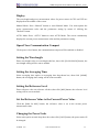
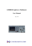
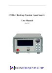
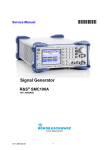
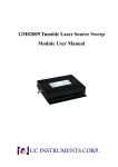
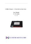
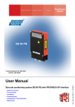
GM8012 Optical Power Meter
User Manual
Aug., 2010
(此图片还没更新为最新)
GM8012 Optical Power Meter User Manual V3.01
Notices
This document contains UC INSTRUMENTS CORP. proprietary information that is
protected by copyright. All rights are reserved. This document can’t be reproduced in
(including electronic storage and retrieval or translation into a foreign language) without
prior agreement and written consent from UC Instruments Corp.
Subject Matter
The material in this document is subject to change without notice.
UC Instruments Corp. makes no warranty of any kind with regard to this printed
material, including, but not limited to, the implied warranties of merchantability and
fitness for a particular purpose.
UC Instruments Corp. shall not be liable for errors contained herein or for incidental or
consequential damages in connection with the furnishing, performance, or use of this
material.
Warranty
This UC Instruments Corp. product is warranted against defects in material and
workmanship for a period of one year from date of shipment. During the warranty
period, UC INSTRUMENTS CORP. will, at its option, either repair or replace products
that prove to be defective.
For warranty service or repair, this product must be returned to a service facility
designated by UC Instruments Corp. Buyer shall prepay shipping charges to UC
Instruments Corp. and UC Instruments Corp. shall pay shipping charges to return the
product to Buyer. However, Buyer shall pay all shipping charges, duties, and taxes for
products returned to UC Instruments Corp. from another country.
UC Instruments Corp. warrants that its software and firmware designated by UC
Instruments Corp. for use with an instrument will execute its programming instructions
when properly installed on that instrument. UC Instruments Corp. does not warrant that
the operation of the instrument, software, or firmware will be uninterrupted or error
free.
10160004 R3.01
www.ucinstruments.com
1
GM8012 Optical Power Meter User Manual V3.01
Limitation of Warranty
The foregoing warranty shall not apply to defects resulting from improper or inadequate
maintenance by Buyer, Buyer-supplied software or interfacing, unauthorized
modification or misuse, operation outside of the environmental specifications for the
product, or improper site preparation or maintenance.
No other warranty is expressed or implied. UC Instruments Corp. specifically disclaims
the implied warranties of Merchantability and Fitness for a Particular Purpose.
Exclusive Remedies
The remedies provided herein are Buyer’s sole and exclusive remedies.
UC Instruments Corp. shall not be liable for any direct, indirect, special, incidental, or
consequential damages whether based on contract, tort, or any other legal theory.
Assistance
Product maintenance agreements and other customer assistance agreements are
available for UC Instruments Corp. products. For any assistance contact the UC
Instruments Corp. Maintenance Service Center.
10160004 R3.01
www.ucinstruments.com
2
GM8012 Optical Power Meter User Manual V3.01
Safety Considerations
The following general safety precautions must be observed during all phases of
operation, service, and repair of this instrument. Failure to comply with these
precautions or with specific warnings elsewhere in this manual violates safety standards
of design, manufacture, and intended use of the instrument. UC Instruments Corp.
assumes no liability for the customer’s failure to comply with these requirements.
Before operation, you should review the instrument and manual for safety markings and
instructions. You must follow these to ensure safe operation and to maintain the
instrument in safe condition.
WARNING: To avoid hazardous electrical shock, do not perform electrical tests
when there are signs of shipping damage to any portion of the outer enclosure (covers,
panels, and so on).
Operating Environment
WARNING : The GM8012 Optical Power Meter is not designed for outdoor use. To
prevent potential fire or shock hazard, do not expose the instrument to rain or other
excessive moisture.
Line Power Requirements
The GM8012 Optical Power Meter complies with overvoltage category II and can
operate from the single-phase AC power source that supplies between 100V and 240V
at a frequency in the range 48 to 66 Hz. The maximum power consumption is 230mA
under 115V voltage. The maximum power consumption is 120mA under 230V voltage.
10160004 R3.01
www.ucinstruments.com
3
GM8012 Optical Power Meter User Manual V3.01
Line Power Connection
In accordance with international safety standards, the instrument has a three-wire power
cable. When connected to an appropriate AC power receptacle, this cable earths the
instrument cabinet.
WARNING: To avoid the possibility of injury or death, you must observe the
following precautions before switching on the instrument.
z
Insert the power cable plug only into a socket outlet provided with a protective
earth contact. Do not negate this protective action by the using an extension cord
without a protective conductor.
z
Do not interrupt the protective earth connection intentionally.
z
Do not remove protective covers. Operating personnel must not remove instrument
covers. Component replacement and internal adjustments must be made only by
qualified service personnel.
z
Instruments that appear damaged or defective should be made inoperative and
secured against unintended operation until they can be repaired by qualified service
personnel.
z
Defective, damaged, or malfunctioning laser sources must be returned to UC
Instruments Corp. Maintenance Service Center.
z
Do not operate the instrument in the presence of flammable gases or fumes.
Operation of any electrical instrument in such an environment constitutes a definite
safety hazard.
Storage and Shipment
The instrument can be stored or shipped at temperatures between -30℃ and +80℃. The
instrument should be protected from temperature extremes that may cause condensation
within it.
10160004 R3.01
www.ucinstruments.com
4
GM8012 Optical Power Meter User Manual V3.01
Table of Contents
GM8012 Optical Power Meter Mainframe .............................. 8
Description of the User Interface..........................................................................9
User Interface Features .........................................................................................9
Pushbuttons.....................................................................................................9
Channel Number .............................................................................................9
Special Optical Head States ............................................................................9
How to Modify the Display? .................................................... 10
Initialization The Display Screen .......................................................................10
The Display Screen ..............................................................................................10
How to Use the Cursor Pushbutton?..................................................................11
How to Change the Channel? .............................................................................11
How to Access the Menu?....................................................................................11
How to Exit from the Menu? ..............................................................................11
How to Accept the New Value of a Parameter?.................................................12
How to Cancel the Editing? ................................................................................12
How to Change the Value of a Parameter?........................................................12
Select a Parameter.........................................................................................12
Editing a Parameter.......................................................................................12
How to Change a Discrete Parameter ? .............................................................13
GM83001D Optical Head......................................................... 14
GM83001D Specification.....................................................................................15
GM83002 Specification........................................................................................15
How to Measure the Power?.................................................... 16
Optical Power Value ............................................................................................16
10160004 R3.01
www.ucinstruments.com
5
GM8012 Optical Power Meter User Manual V3.01
How to Set the Number of Digits? ......................................................................16
Optical Power Units.............................................................................................17
What are the Optical Power Units? ...................................................................17
How to Set the Optical Power Units?.................................................................17
Power Reference Level ........................................................................................18
How to Set the Reference Level? ........................................................................18
How to Set the Reference Value to the Current Power Value?........................19
How to Set the Wavelength? ...............................................................................20
How to Perform a Zero?......................................................................................21
How to Set the Averaging Time ..........................................................................22
How to Choose the MinMax Mode?...................................................................23
How to Reset MinMax Buffer?...........................................................................24
Communication Interface ........................................................ 25
RS232 Serial Interface Port ................................................................................25
Fixed Parameters...........................................................................................25
RS232 Connector..........................................................................................25
Cable .............................................................................................................26
USB Port ...............................................................................................................26
USB Connector .............................................................................................26
USB Cable ....................................................................................................26
AC Line Power Supply Requirements.................................... 27
Line Power Requirements ...................................................................................27
Line Power Cable.................................................................................................27
Claims and Repackaging ......................................................... 28
Return Shipments to UC Instruments Corporation.........................................28
UC Instruments Corp. Maintenance Service Center .......................................28
10160004 R3.01
www.ucinstruments.com
6
GM8012 Optical Power Meter User Manual V3.01
Standard Equipments .............................................................. 29
Maintenance.............................................................................. 29
GM8012 Specification .............................................................. 30
GM8012 Specifications ........................................................................................30
GM8001B Performance Tests ................................................. 31
Equipment Required ...........................................................................................31
Test Failure ...........................................................................................................31
Instruments Specifications ..................................................................................31
Performance Test Instructions............................................................................32
Test Record ............................................................................... 34
Software Installation ................................................................ 35
System Set Up ........................................................................... 37
Operation .................................................................................. 37
Display...................................................................................................................38
Open/Close Communication Comport...............................................................38
Setting the Wavelength ........................................................................................38
Setting the Averaging Time .................................................................................38
Setting the Reference Level.................................................................................38
Set the Reference Value to the Current Power Value .......................................38
Changing the Power Units...................................................................................38
Enable MinMax Mode.........................................................................................39
Disable MinMax Mode ........................................................................................39
Reset MinMax Buffer ..........................................................................................39
Performing a zero ................................................................................................39
UC INSTRUMENTS CORP. CONTACT INFORMATION
10160004 R3.01
www.ucinstruments.com
7
GM8012 Optical Power Meter User Manual V3.01
GM8012 Optical Power Meter Mainframe
The GM8012 Dual Channels Optical Power Meter is a high-accuracy, wide-range
optical power Measuring Instruments. It uses new data collecting and processing
method and features larger Signal Noise Ratio and Dynamic Range, quick Response
Speed. The power measurement range is from +3 to -80dBm or from +23 to -60dBm
optional.
The GM8012 Instruments do not need adjustment and is very easy to operate. It is used
for direct power measurement or power loss relative measurement. The GM8012 is a
base measurement instruments for Tele-com and the characterization and feature
evaluation of optical fiber and optical cable, optical passive component.
This section will introduce the features of GM8012 Optical Power Meter. Here you will
find a brief description of the instrument, how to use the user interface and how to
perform a simple sample session.
Figure 1 - GM8012 Mainframe
图片未更新
10160004 R3.01
www.ucinstruments.com
8
GM8012 Optical Power Meter User Manual V3.01
Description of the User Interface
LCD display
Power key
Push button
Channel 1
Channel 2
RS232 Port
USB Port
AC Power coupler
Figure 2 - User interface of the GM8012 Power Meter
User Interface Features
PushButtons
All the control to GM8012 is via the push buttons.
Channel Number
Each optical head is identified by a channel number, the channel number represents the
head’s position in the mainframe, from one to two from left to right for the GM8012.
These numbers are displayed on the top of each optical head channel on the front panel.
Special Optical Head States
If the channel is empty, you will see EMPTY information shown instead of parameter or
measurement values.
10160004 R3.01
www.ucinstruments.com
9
GM8012 Optical Power Meter User Manual V3.01
How to Modify the Display?
Initialization The Display Screen
When the GM8012 is powered up, the screen will show initial information, such as, the
serial number, hardware revision, firmware revision of the GM8012, and information
about two channels.
*****CH2:Selftest: ………….
Model:GM83001 Serial
Number:GG032614002
CalData Load OK!
Figure 3 - Screen for Detecting the Optical Head in Channel 2
The Display Screen
Figure 3 shows the screen profile of the GM8012 Power Meter. This screen will show
up immediately after start-up. The screen shows the wavelength and power
measurement value of the power meter module.
Wavelength for Channel 1
Measured Power
For Channel 1
Power Units
For Channel 1
Wavelength for Channel 2
CH1: 1545nm
CH2: 1548nm
-36.656
-78.623
dBm
dBm
Measured Power
For Channel 2
Power Units
For Channel 2
Figure 4 - GM8012 Display Screen
10160004 R3.01
www.ucinstruments.com
10
GM8012 Optical Power Meter User Manual V3.01
How to Use the Cursor Pushbutton?
In menu system, you can move to the previous parameter by using [◀] cursor
pushbutton, and move to the next parameter by [▶]. Continuing to press [▶] cycles
through the last parameter after which the screen shows the first parameter and the cycle
begins again. Pressing the [◀] pushbutton is in a similar way.
When editing a parameter, the [▲] and [▼] pushbuttons can be used to increment and
decrement the value of a digit and the [◀]and [▶] pushbuttons can be used to move the
highlighted digit left and right.
How to Change the Channel?
You can switch optical head channel by pressing the [CHAN] pushbutton.
How to Access the Menu?
Press the [MENU] pushbutton to access all the parameters and functions that apply to a
module. Figure 5 show the menu screen you should see for a power meter module.
CH2: System Parameter
1/9 MinMax Mode
Figure 5 - Menu of GM8012 Power Meter
How to Exit from the Menu?
Press the [CHAN] pushbutton to return to Previous menu. Continuing to press [CHAN]
pushbutton, you exit from the menu system.
10160004 R3.01
www.ucinstruments.com
11
GM8012 Optical Power Meter User Manual V3.01
How to Accept the New Value of a Parameter?
When you changed the value of a parameter, Press the [MENU] pushbutton to accept
this change.
How to Cancel the Editing?
If you make a mistake while you are editing a parameter, you can cancel the editing,
and retain the previous value for the parameter by pressing the [CHAN] pushbutton.
How to Change the Value of a Parameter?
What follows is a description of the way of change the value of parameters.
Select a Parameter
Press the [MENU] pushbutton to enter menu system, and then move to the target
parameter by pressing [◀] or [▶] pushbutton.
Editing a Parameter
To start editing a parameter,
1
Press the [MENU] twice to enter editing mode,
2
The digit before decimal point of setting value will be highlighted first, as shown in
Figure 5.
CH2: System
Parameter
4/9 Wavelength
Set: 1540.0 nm
Figure 6 - Editing a parameter
3
Enter the new value for the highlighted digit by using the [▲ ] and [ ▼ ]
pushbuttons.
10160004 R3.01
www.ucinstruments.com
12
GM8012 Optical Power Meter User Manual V3.01
4
If you want to select another digit to edit, use the [◀] and [▶] pushbuttons.
5
Repeat steps 3 and 4 to continue editing the value.
5
When you have finished editing the value, press [MENU]. The edited value
becomes the new value of the parameter.
6
But, if you want to cancel the change, press [CHAN].
How to Change a Discrete Parameter ?
For discrete parameters, you may choose a particular value within a given range.
For example, set the averaging time:
1
Press the [MENU] pushbutton.
2
Move to the <Averaging Time> parameter and press [MENU] twice. You see the
screen in Figure 6.
CH2: System
Parameter
5/9 Averaging time
Set:
100 ms
Figure 7 - Set Averaging Time
3
Move to required value, by using the [◀] and [▶] pushbuttons, then press the
[MENU].
10160004 R3.01
www.ucinstruments.com
13
GM8012 Optical Power Meter User Manual V3.01
GM83001D Optical Head
An Optical Head measures the power emitted from a connected single-mode Fiber. The
wavelength and power range depend on the sensor element.
The GM8012 mainframe has two channel adaptors for connecting with optical heads.
Optical Fiber
Interface
Self-locked Plug
Figure 8 - GM83001D Optical Head
Put on an optical-fiber adaptor to the GM83001D’s Optical Head.
When you connect a GM83001D Optical Head to the GM8012 Mainframe, make sure
that the red dot on the Self-locked Plug of GM83001D is align to the same one on the
adaptor on the front panel of GM8012, then push the Self-locked connector into the
GM8012’s adaptor.
In order to remove the GM83001D from GM8012, first turn the self-locked connect,
then pull the self-locked connector out of the adaptor in horizontal direction.
10160004 R3.01
www.ucinstruments.com
14
GM8012 Optical Power Meter User Manual V3.01
GM83001D Specification
GM83001
Model #
Single Channel InGaAs
Sensor Element
Wavelength Range
850 ~ 1700 nm
Power Range
+3 ~ -80 dBm
Resolution
Application Fiber Type
Uncertainty (accuracy) at
reference condition
Relative Uncertainty (accuracy)
at reference condition
Linearity (power)
Return Loss
Operation Temperature
xW:0.01
dBm/dB:0.001、0.01、0.1 optional
Standard SM and mm up to 62.5 um core size
+/- 4% (1200 nm ~ 1610 nm)
< 0.02 dB, Typical
<= +/- 0.06 dB (1200 nm ~ 1610 nm, + 0~ -60 dBm)
> 40 dB
0 ~ +40℃
Storage Temperature
-30 ~ +80℃
Recalibration Period
2 years
GM83002 Specification
GM83001
Model #
Single Channel InGaAs
Sensor Element
Wavelength Range
850 ~ 1700 nm
Power Range
+ 23 ~ -60 dBm
Resolution
Application Fiber Type
Uncertainty (accuracy) at
reference condition
Relative Uncertainty (accuracy)
at reference condition
Linearity (power)
Return Loss
Operation Temperature
xW:0.01
dBm/dB:0.001、0.01、0.1 optional
Standard SM andmm up to 62.5 um core size
+/- 4% (1200 nm ~ 1610 nm)
< 0.02 dB, Typical
<= +/- 0.06 dB (1200 nm ~ 1610 nm, + 0~ -60 dBm)
> 40 dB
0 ~ +40℃
Storage Temperature
-30 ~ +80℃
Recalibration Period
2 years
10160004 R3.01
www.ucinstruments.com
15
GM8012 Optical Power Meter User Manual V3.01
How to Measure the Power?
Optical Power Value
The screen displays the power measurement value in general. In MinMax mode, this
power measurement value changes to <ΔP>, the difference between minimum and
maximum power, and the power minimum value measured, <Min>, and the power
maximum value measured <Max>, see “How to Choose the MinMax Mode”.
How to Set the Number of Digits?
You can set the maximum number of digits that are used in optical power measurement.
This is the maximum number of digits after the decimal point.
To change the number of digits to two:
1
Select the Power Meter Channel using [CHAN], and press the [MENU],
2
Move to <Number of Digits> option and press [MENU].
3
Press [MENU] again to enter editing mode,
CH2: System
3/9
Set:
Parameter
Data Points
1
Figure 9 - Set Averaging Time
4
Move to “2” by using the [◀] or [▶] pushbutton, and press [MENU].
5
Press the [CHAN] to exit the menu.
10160004 R3.01
www.ucinstruments.com
16
GM8012 Optical Power Meter User Manual V3.01
Optical Power Units
Pressing the [UNIT] pushbutton allows you to select either nW, dB, or dBm as the units
in which power is displayed.
What are the Optical Power Units?
Watts (W) is the SI unit for power measurement.
You can also measure power in dB or dBm. Values displayed in these units are derived
from measurement in Watts.
By selecting dBm, the following calculation is made:
Where,
PdBm is the power value displayed in dBm, and
Pinput is the input signal level in Watts.
Power, in units of dBm, is measured relative to 1 mW, it is an absolute power
measurement.
By selecting dB, the following calculation is made:
Where,
PdB is the power value displayed in dB,
Pinput is the input signal level in Watts,
Pref is the chosen reference power value in Watts.
How to Set the Optical Power Units?
You can change the power unit on display screen or in menu system.
To set the power unit to dBm:
1
Select the Power Meter Channel using [CHAN].
2
Press the [UNIT] pushbutton.
3
The unit of power will be changed to nw or dB or dBm when you press [UNIT].
10160004 R3.01
www.ucinstruments.com
17
GM8012 Optical Power Meter User Manual V3.01
or
1
Select the Power Meter Channel using [CHAN], and press [MENU].
2
Move to <8/9 Pwr unit>, then press [MENU].
3
Press [MENU] again to enter editing mode,
4
Move to <dBm> by using the [◀] or [▶] pushbutton, then press [MENU].
5
Press the [CHAN] to exit the menu.
Power Reference Level
How to Set the Reference Level?
dB results are shown relative to a reference level. The <Reference> parameter in menu
sets the power reference level. Setting, or changing the reference only affects results
that are displayed in dB.
The following equations are used to calculate the power level in dB:
Where,
Pdisplay
Pmeasured
REF
is the displayed relative power,
is the absolute power level,
is the reference level. The units is dBm.
To set the reference level to 10 dBm:
1
Select the Power Meter Channel using [CHAN], and press [MENU].
2
Move to the <7/9 Reference> by pressing [▶] pushbutton and press the [MENU].
3
Press [MENU] again to enter editing mode,
CH2: System
7/9
Set:
Parameter
Reference
+00.010 dBm
Figure 10 - Set Reference Level
10160004 R3.01
www.ucinstruments.com
18
GM8012 Optical Power Meter User Manual V3.01
4
Enter 10 by using the cursor pushbuttons.
5
Press [MENU] softkey to confirm the new reference level.
6
Press the [CHAN] to exit the menu.
How to Set the Reference Value to the Current Power Value?
In addition to entering a new reference value, you can change the reference value to the
currently displayed power value by pressing the [Ref] pushbutton.
Pressing the [Ref] pushbutton takes the input power and stores it as the reference.
Setting the reference only affects results displayed in dB.
When you press the [Ref], the power units must be dBm or nW. The power is stored as
the reference, that is:
REF = Pmeasured
Where,
REF is the reference, and
Pmeasured is the absolute power level in Watts or dBm.
You can also set the reference value to the currently displayed power value in menu
system.
1
Select the Power Meter Channel using [CHAN], and press [MENU].
2
Move to the <9/9 Disp to Ref> by pressing [▶] pushbutton and press the [MENU].
3
Press [MENU] again to enter editing mode,
CH2: System
9/9
Set:
Parameter
Disp to Ref
Disp to Ref
Figure 11 - Set Reference Level to the currently displayed power
4
Press [MENU].
5
Press the [CHAN] to exit the menu.
10160004 R3.01
www.ucinstruments.com
19
GM8012 Optical Power Meter User Manual V3.01
How to Set the Wavelength?
This is the wavelength value. The responsivity of the Power Meter varies with
wavelength. For accurate power measurement, you need to set the wavelength of the
optical input.
To set the wavelength to 1545.0nm:
1
Select the Power Meter Channel required to change the wavelength value using the
[CHAN], and press [λ] pushbutton.
CH1: Empty
CH2: 1548nm
-78.623
dBm
Figure 12 - Set the Wavelength by using [λ] pushbutton
2
The highlight toggles the last digit of the wavelength value. Press the [▲] and [▼]
pushbuttons to modify the value of the highlighted digit. Press the [◀] and [▶] to
select another digit required to change until the current value is changed to 1545.
3
Press [MENU].
Or you can do this:
1
Select the Power Meter Channel using [CHAN], and press [MENU],
2
Move to the <4/9 Wavelength> and press the [MENU],
3
Press [MENU] again to enter editing mode,
CH2: System
Parameter
4/9 Wavelength
Set: 1540.0 nm
Figure 13 - Set the Wavelength in Menu System
4
Enter 1545.0 by using the cursor pushbuttons, and press [MENU].
5
Press the [CHAN] to exit the menu.
10160004 R3.01
www.ucinstruments.com
20
GM8012 Optical Power Meter User Manual V3.01
How to Perform a Zero?
Optical Power Meters measure optical power by converting optical power to electrical
power, and then measuring electrical power. An electrical offset is electrical power that
is always present, even if there no optical power is input. If electrical offsets are not
removed, they affect the accuracy of power measurement.
Performing a zero sets the zero power level to the average electrical offset level for the
current environmental conditions.
NOTE: The environmental conditions and the temperature of the instrument affect
electrical offset. For the best results you must:
z
Allow the instrument time to perform a zero during operation (per 1 hour).
z
Allow the instrument time to warm up (around 20 minutes).
z
Make sure that the optical input is not receiving any light. If you are using
multi-mode fiber-optic cable, you must disconnect the cable and cover the input to
the Power Meter to perform a zero.
It is good practice to perform a zero before making any important measurements.
To remove electrical offsets:
1
Cover the input to the Power Meter and make sure the optical input is not receiving
any light.
2
Select the Power Meter Channel.
3
Press [ZERO] pushbutton to zero the current power measurement. You will see texts
for “Zeroing . . .” in place of the displayed power value, this appears for around 10
seconds while zeroing is performed.
CH1: 1545nm
Zeroing…
CH2: 1548nm
-78.623
dBm
Figure 14 - Performing a Zeroing
10160004 R3.01
www.ucinstruments.com
21
GM8012 Optical Power Meter User Manual V3.01
Or
1
Select the Power Meter Channel, and press [MENU],
2 Move to the <6/9 Zero> and press the [MENU],
3
Press [MENU] again to zero the current power measurement. You will see the
background for “Zeroing . . .” is darken, this appears for around 10 seconds while
zeroing is performed.
CH2: System
Parameter
6/9 Zero
Set:
Zeroing
Figure 15 - Performing a Zeroing
How to Set the Averaging Time
This is the length of time over which a signal is averaged. Longer averaging times
increase the accuracy and improve the noise rejection. Longer averaging times also
decrease sensitivity.
The averaging time may be selected from 1ms、2ms、5ms、10ms、20ms、50ms、100ms、
200ms、500ms、1000ms、2000ms、5000m s、10000ms.
For example, set the averaging time to 500ms:
1
Select the Power Meter Channel, and press [MENU],
2
Move to the < 5/9 Averaging Time> by using the [▶], and press [MENU],
CH2: System
Parameter
5/9 Averaging time
Set:
200 ms
Figure 16 – Set Averaging Time
3
Press [MENU] again to enter editing mode,
4
Move to <500ms> by using the [◀] or [▶] pushbutton, then press [MENU].
10160004 R3.01
www.ucinstruments.com
22
GM8012 Optical Power Meter User Manual V3.01
How to Choose the MinMax Mode?
MinMax mode measures the input power and displays the minimum value measured,
<Min>, and the maximum value measured, <Max>. The difference between these values,
<ΔP>, is displayed in place of P, the power value. This mode is intended principally for
polarization dependent measurements, but can be used for other types of measurement.
CH1:1548nm
CH2:1548nm
-78.623
ΔP
0.45 dB
Min -5.46 dB
Max -5.03 dB
dBm
Figure 17 - MinMax mode -> Continuous
You can choose the modes of operation from the MinMax mode menu:
z
<Off> mode, which turns off MinMax mode, and returns to continuous power
measurement.
z
<Continuous> mode, which compares each new measured value with the maximum
and minimum values so far, and replaces them as necessary.
This mode is useful for measuring the Polarization Dependent Loss (PDL) of a
component. Run the application while sweeping the polarization of the source
applied to the component.
To turn off MinMax mode, and return to continuous power measurement:
1
Select the Power Meter channel using [SEL], and press the [MENU].
2
Move to the <1/9 MinMax Mode> and press [MENU].
3
Press [MENU] again to enter editing mode,
4
Move to <Off> by using the [◀] or [▶] pushbutton, and press [MENU].
5
Press the [CHAN] to exit the menu.
10160004 R3.01
www.ucinstruments.com
23
GM8012 Optical Power Meter User Manual V3.01
How to Reset MinMax Buffer?
If the MinMax Mode is not set to Off mode, a buffer will be used. Reset the buffer, the
power minimum and maximum values are set to currently displayed power value.
To reset the MinMax buffer:
1
Select the Power Meter channel using [SEL], and press the [MENU].
2
Move to the <2/9 Reset MinMax> and press [MENU].
3
Press [MENU] again to enter editing mode,
CH2: System
Parameter
1/9 Reset MinMax
Set: Reset MinMax
Figure 18 – Reset a MinMax Buffer
4
Press [MENU] to reset the buffer. The system jumps to the display screen.
10160004 R3.01
www.ucinstruments.com
24
GM8012 Optical Power Meter User Manual V3.01
Communication Interface
There are two communication interface ports on the rear panel of the GM8012. They are
USB port and RS232 serial interface port.
RS232 Serial Interface Port
The GM8012 serial interface has fixed parameters.
The PC serial interface should be configured to match the instrument’s fixed
parameters.
Fixed Parameters
These are:
Baudrate
115200
Data Bits
8
Parity
None
Stop Bits
1
RS232 Connector
The following figure 19 shows the connector and pin assignments.
2- Transmit data
3- Received data
5-Signal ground
Figure 19 - RS232 Connector
10160004 R3.01
www.ucinstruments.com
25
GM8012 Optical Power Meter User Manual V3.01
Cable
The connetors pin assignments on the cable for RS232 Communication.
DB9 CONNECTOR
PIN
NOTES
Received data
2
Transmit data
3
Signal ground
5
DB9 CONNECTOR
PIN
NOTES
Transmit data
2
Received data
3
Signal ground
5
NOTE For serial communication use the null modem cable provided with your
instrument.
USB Port
The USB Port is for connection to PC with PC software.
USB Connector
This is a standard four-core type B USB connector.
USB Cable
The USB connection cable must not be extended beyond 5m. For distance over 5m, it is
possible to use a third party USB extender. Typically, they extend USB up to 50m.
10160004 R3.01
www.ucinstruments.com
26
GM8012 Optical Power Meter User Manual V3.01
AC Line Power Supply Requirements
Line Power Requirements
The GM8012 Optical Power Meter complies with overvoltage category II and can
operate from the single-phase AC power source that supplies between 100V and 240V
at a frequency in the range 48 to 66 Hz. The maximum power consumption is 230mA
under 115V voltage. The maximum power consumption is 120mA under 230V voltage.
Line Power Cable
In accordance with international safety standards, the instrument has a three-wire power
cable. When connected to an appropriate AC power receptacle, this cable earths the
instrument cabinet.
GM8012 Power Key
The power key on the front panel of the GM8012 may turn on or turn off the power.
WARNING: To avoid the possibility of injury or death, you must observe the
following precautions before switching on the instrument.
z
Insert the power cable plug only into a socket outlet provided with a protective
earth contact. Do not negate this protective action by the using an extension cord
without a protective conductor.
z
Do not interrupt the protective earth connection intentionally.
The AC power requirements are summarized on the rear panel of the instrument.
AC INPUT:
100-240V~, 48-66Hz, 48~ 66Hz
230mA/115V, 120mA/230V,
AC Power Requirement Mark - GM8012
10160004 R3.01
www.ucinstruments.com
27
GM8012 Optical Power Meter User Manual V3.01
Claims and Repackaging
If physical damage is evident or if the instrument does not meet specification when
received, notify the carrier and the UC Instruments Corp. Maintenance Service Center.
The Maintenance Service Center will arrange for repair or replacement of the unit
without waiting for settlement of the claim against the carrier.
Return Shipments to UC Instruments Corporation
If the instrument is to be shipped to a UC Instruments Corp. Maintenance Service
Center, attach a tag showing owner, return address, model number and full serial
number and the type of service required.
The original shipping carton and packing material may be reusable, but the UC
Instruments Corp. Maintenance Service Center will provide information and
recommendation on materials to be used if the original packing is no longer available or
reusable.
General instructions for repackaging are as follows:
z
Wrap instrument in heavy paper or plastic.
z
Use strong shipping container.
z
Use enough shock absorbing material (3 to 4 inch layer) around all sides of the
instrument to provide a firm cushion and prevent movement inside container.
Protect control panel with cardboard.
z
Seal shipping container securely.
z
Mark shipping container FRAGILE to encourage careful handling.
z
In any correspondence, refer to instrument by model number and serial number.
UC Instruments Corp. Maintenance Service Center
Any adjustment, maintenance, or repair of GM8012 must be performed by qualified
personnel. Contact your customer engineer through UC Instruments Corp. Maintenance
Service Center.
Tel:0773-5850657, 5803731
http://www.ucigl.com
10160004 R3.01
www.ucinstruments.com
28
GM8012 Optical Power Meter User Manual V3.01
Standard Equipments
The GM8001B Lightwave Multimeter is available in various configurations for the best
possible match to the most common applications.
This appendix provides information about GM8012’s Standard Equipments
Accessories
Model #
AC Power Cable
Description
null modem cable
standard four-core type B USB cable.
three-wire power cable
CD
Includes GM8012 User manual and PC software
RS232 Cable
USB Connection Cable
Optical Head Interfaces
Model #
Description
GM83001D
Single Channel Optical Head
Maintenance
z
Avoid sharp vibration when operation.
z
Keep the head face of sensor clean.
z
Cover the channel adaptor on the front panel with the dust cap.
z
Don’t forcibly push or drag the GM83001D’s self-locked connector out of the
adaptor of GM8012.
z
Clean the lens interface by rubbing the lens cleaning paper over the surface using a
small circular movement.
z
Be careful for crash and fall-off.
10160004 R3.01
www.ucinstruments.com
29
GM8012 Optical Power Meter User Manual V3.01
GM8012 Specification
The GM8012 Optical Power Meter is produced to the ISO9001 international quality
system standard. UC Instruments Corp. continually increases customer satisfaction
through improved quality control.
Specifications describe the instruments warranted performance. Supplementary
performance characteristics describe the instruments non-warranted typical
performance.
GM8012 Specifications
Display
192 X 64 points visible, monochrome
Display Resolution
0.001 dB/dBm, 0.001 nW / uW / mW
Compatibility
The GM8012 mainframe supports all
GM8300X Serial Optical Head
Data Acquisitions
Memory
Selectable data averaging time
Selectable total data averaging time
16M bits, flash
Depends on sensor module
20 ms to 23:59:59 h
Environmental
Storage temperature
Operating temperature
Humidity
−30°C to +80°C
0°C to +40°C
<95% R.H. from 0°C to +45°C
Power
AC 100 - 240 V, 48 - 66 Hz, 230mA max.
Dimensions
270 mm X 200 mm X 120 mm (LWH)
Interfaces
RS232 Serial Port, USB interface Port
Number of Optical heads
2 Optical Heads
10160004 R3.01
www.ucinstruments.com
30
GM8012 Optical Power Meter User Manual V3.01
GM8001B Performance Tests
The GM8012 do not contain calibration data, therefore they are not subject to
re-calibration. Consequently, these Performance Tests test the functionality of the
instrument.
The GM8012 comprises a power supply, a CPU, multi-keys panel, and a display. All
tests can be performed without access to the interior of the instrument.
Equipment Required
Equipment required for the performance test is listed in the table below. Any equipment
that satisfies the critical specifications given in the table may be substituted for
recommended models in the round brackets.
Description
Mainframe
Optical Head
Single-mode Fiber (FC/PC)
Model
GM8012
GM83001Optical Head(GM83002)
Test Failure
If the GM8012 Optical Power Meter fail any Performance Test, return the instrument to
the UC Instruments Corp. Maintenance Service Center for repair.
Instruments Specifications
Any changes in the specifications due to manufacturing changes, design, or traceability
to the National Institute of Standards and Technology will be covered in a manual
change supplement or revised manual. The specifications listed here supersede any
previously published.
NOTE Make sure that all optical connections of the test setups given in the procedure
are dry and clean. DO NOT USE INDEX MATCHING OIL. For cleaning, use the
cleaning instructions.
10160004 R3.01
www.ucinstruments.com
31
GM8012 Optical Power Meter User Manual V3.01
Figure 20- GM8012 Mainframe with two GM83001D optical heads
Performance Test Instructions
Setup
1
Setup the test equipment as shown in Figure 20.
Connect two GM83001 Optical Heads to CH1 and CH2 of GM8012.
Connect a fiber with the Optical Head in CH1.
2
Switch on the GM8012 and wait until it has booted.
Testing [CHAN] Pushbutton
3
Press [CHAN] pushbutton several times, the highlighted field on the display should
toggle between the two channels.
4
Move the highlight to “CH1”.
Testing Cursor Pushbuttons and [MENU] Pushbutton
5
Press [λ] Pushbutton to edit the wavelength.
Check the highlighted fields toggles the wavelength value .
6
Press the [◀] and [▶] pushbuttons several times.
Check the highlighted fields moves to the digits of wavelength value right and left.
7
Press the [▲] and [▼] pushbuttons.
Increment or Decrement the value of the highlighted digit.
8
Press the [MENU] to confirm the new wavelength.
10160004 R3.01
www.ucinstruments.com
32
GM8012 Optical Power Meter User Manual V3.01
Testing Absolute Optical Power Value
1
Press [UNIT] several times until dBm appears.
2
Note the power reading of the power meter in the test record.
Testing Relative Optical Power Value
1 Press [UNIT] several times until the power units is changed to dB.
2 Press [REF] pushbutton.
3 Note the power reading of the power meter in the test record.
The related equation is
Prelative (dB)=Pabsolute (dBm) – PREF(dBm)
The Module Performance Test ends here.
10160004 R3.01
www.ucinstruments.com
33
GM8012 Optical Power Meter User Manual V3.01
Test Record
GM8012 Optical Power Meter Performance Test
Date _________
Serial No. _____________________
Options _______________________
Firmware Rev. _________________
Test Facility ___________________
Performed by __________________
Ambient Temperature _________ ℃
Relative Humidity _________ %
Line Frequency _________ Hz
Customer ___________________
Report No ___________________
Special Notes _______________________________________________
___________________________________________________________
___________________________________________________________
___________________________________________________________
Test Equipment Used
Description
Model No.
1 Optical Fiber
2 Optical Head
3 ______________________
4 ______________________
5 ______________________
6 ______________________
___________
___________
___________
___________
___________
___________
Display / Pushbutton Function
Test of the [CHAN] pushbutton
Test of the Cursor pushbutton
Trace No
___________
___________
___________
___________
___________
___________
Cal. Due Date
___________
___________
___________
___________
___________
___________
Check the appropriate function
Passed
Failed
___________
___________
___________
___________
Module Test
Test of
Absolute
Value
Relative
Value
CH1
_______
_______
0.000dB ______
______
CH2
_______
_______
0.000dB ______
______
10160004 R3.01
Check the appropriate function
Max Spec Passed
Failed
www.ucinstruments.com
34
GM8012 Optical Power Meter User Manual V3.01
Software Installation
If you use USB port to communication with PC, before operating the GM8012, two
software components must be installed first
1
First install the USB driver CP210x_VCP_Win2K_XP_S2K3.EXE. For Windows 7,
please use CP210x_VCP_Win7.EXE.
Please find the USB driver in UC Instruments CD.
2. Now install the demonstration program for GM8012 following the procedures
below.
a) Double click GM8012 xxx setup.exe
10160004 R3.01
www.ucinstruments.com
35
GM8012 Optical Power Meter User Manual V3.01
b) Specify the installation directory, then click “Next” button
c) Wait for the “Finish” button to appear then click it to complete the installation
10160004 R3.01
www.ucinstruments.com
36
GM8012 Optical Power Meter User Manual V3.01
System Set Up
1
Power up the GM8012.
2
Connect the PC to the GM8012 with the supplied USB cable, the PC will prompt
for installing the hardware automatically. After completing the installation, open
the windows device manager, and look for added comport under ‘comport(COM
and LPT)’. The PC assigns a com port number automatically.
3
You can also use a RS232 cable supplied by UC Instruments Corp. to Connect the
PC to the GM8012.
Assume you use a USB port in this section.
4
Run the demonstration program, select the above comport (COM4 in this example),
baud rate is set to 115200, press “open” button to establish the communication
between the PC and the GM8012.
Operation
When the GM8012 communicates with pc, the interface is shown below.
10160004 R3.01
www.ucinstruments.com
37
GM8012 Optical Power Meter User Manual V3.01
Display
The wavelength and power measurement values for power meters in CH1 and CH2 are
displayed on the middle of the screen.
Manual Mode: Press “Manual” button to enter Manual Mode. You must update the
power measurement value and the parameters setting by means of clicking the
“Refresh” button.
AUTO Mode: Press “AUTO” button to enter AUTO Mode. The screen continuously
displays the current power measurement value and the parameters setting.
Open/Close Communication Comport
Click open or close button, the communication comport will be enabled or disabled.
Setting the Wavelength
Enter wavelength value on wavelength edit box, then click [WAVELENGTH] button, the
wavelength setting will be sent to module.
Setting the Averaging Time
Select averaging time option on averaging time drop-down box, then click [ATIME]
button, the averaging time setting will be sent to module.
Setting the Reference Level
Enter reference value on reference edit box, then click [REF] button, the reference level
setting will be sent to module.
Set the Reference Value to the Current Power Value
Click the [DISP TO REF] button, the reference value is set to the current power
measurement value.
Changing the Power Units
Select units option on unit drop-down box, then click [UNIT] button, the power unit will
be changed.
10160004 R3.01
www.ucinstruments.com
38
GM8012 Optical Power Meter User Manual V3.01
Enable MinMax Mode
Click the [MINMAXMODE ON] button to enable the MinMax Mode.
Disable MinMax Mode
Click the [MINMAXMODE OFF] button to disable the MinMax Mode and return to
continuous power measurement.
Reset MinMax Buffer
Click the [RESET MINMAX] button to reset the MinMax buffer.
Performing a zero
Click the [ZERO] button to zero the current power measurement.
Notice, Cover the input to the Power Meter and make sure the optical input is not
receiving any light before performing a zero.
10160004 R3.01
www.ucinstruments.com
39
GM8012 Optical Power Meter User Manual V3.01
UC INSTRUMENTS CORP. CONTACT INFORMATION
UC INSTRUMENTS CORPORATION
Add: 37498 Glenmoor Dr., Fremont, CA 94536 USA
Tel: +1-510-366-7353
Fax: +1-510-353-1809
Email: [email protected]
Website: www.ucistruments.com
MAINTENANCE SERVICE CENTER,GUILIN,CHINA
Address:No.16 Yi Feng south road, GuiLin, China
Tel: +86 773 5850657
Fax: +86 773 5814532
Website: www.ucigl.com
10160004 R3.01
www.ucinstruments.com
40