1
US007794315B2
(12) United States Patent
(10) Patent N0.:
(45) Date of Patent:
Sakaguchi et al.
(54)
ROLE PLAY SYSTEM
(US); Takehiro Kaminagayoshi, Tokyo
(JP)
(73) Assignee: Microsoft Corporation, Redmond, WA
(Us)
Notice:
Sep. 14, 2010
“Madden 2005” Game user manual, release date in US. established
(75) Inventors: Hironobu Sakaguchi, Honolulu, HI
(*)
US 7,794,315 B2
as of Sep. 7, 2004. http://d0Wnl0ads.plantermirrorcom/pub/
repl ac ementdoc s/Maddeni200 Sf-fManualf-fPlaystationZ.
“X-Men Legends” Game user manual, release date in US. estab
lished as of Sep. 21, 2004. http://d0Wnl0ads.planetmirrorcom/pub/
replacementdocs/XiMeniLegendsi-iManuali-iXbox.pdf.*
X-Men Legends “A breath of fresh air in t0 the X-men Universe”
http://WWW.gamefaqs.com/c0ns01e/Xb0X/revieW/R80 l78,html.*
Subject to any disclaimer, the term of this
patent is extended or adjusted under 35
U.S.C. 154(b) by 1071 days.
“X-Men Legends” Game user manual, release date established as of
Sep.
21,
2004.
http://d0Wnl0ads.planetmirrorcom/pub/
replacementdocs/XiMeniLegendsi-iManuali-iXbox.pdf.*
“Dynasty Warriors” Game user manual, release date established as of
Feb.
24,
2005.
http://d0Wnl0ads.planetmirrorcom/pub/
(21) Appl. No.: 11/221,793
repl ac ementdoc s/DynastyfWarriorsiSi-iManuali-iPSZ .pdf. *
(22) Filed:
* cited by examiner
Sep. 9, 2005
Primary Examinerilohn M Hotaling
(65)
Prior Publication Data
US 2007/0060343 A1
(51)
Assistant ExamineriEric M Thomas
(74) Attorney, Agent, or FirmiLee & Hayes, PLLC
Mar. 15, 2007
(57)
Int. Cl.
A63F 13/00
(2006.01)
(52)
US. Cl. ............................................. .. 463/9; 463/1
(58)
Field of Classi?cation Search ................... .. 463/1,
463/9, 29
See application ?le for complete search history.
(56)
U.S. PATENT DOCUMENTS
6,758,756
B1 *
10/2000
7/2004
Miyamoto et al. .......... .. 463/32
Horigami et al.
......
2005/0187023 A1 *
8/2005 Miyamoto et al. .
2006/0205456 A1 *
9/2006
A video game system and method is described in Which a
player-controlled icon in a map scene represents a group or
party of characters, and in response to the icon entering a
location on the map scene, automatically dispersing the icon
into multiple icons representing the various characters. Upon
dispersing, the various characters may automatically move to
different areas of the location based on individual character
preferences. The player may choose to control one of the
References Cited
6,139,434 A *
ABSTRACT
. . . .. 463/43
463/43
BentZ et al. .................. .. 463/1
characters in the location and interact With one or more char
acters/ objects in the location. The interaction may be
recorded as it occurs, and the player may sWitch control to a
different character and play the same interaction from a sec
ond character’s point of vieW. Under the second character’s
point of vieW, the original interaction and/ or its outcome may
OTHER PUBLICATIONS
“Super Mario 64” Game user manaul, release date in US. establised
be changed.
as of Sep. 29, 1996. http://downloads.planetmirr0r.com/pub/
replacementdoc s/SuperiMari0i64i-iManuali-iN64 .pdf. *
701 b
701a
17 Claims, 10 Drawing Sheets
US. Patent
10
Sep. 14, 2010
Sheet 1 0f 10
US 7,794,315 B2
US. Patent
Sep. 14, 2010
Sheet 2 0f 10
US 7,794,315 B2
{-100
r
214_
|_
_
GAME CONSOLE E
-
|
L
_
_
_
_
-
_
-
-
_
CENTRAL PROCESSING UNIT M
~
LEvEL 1 CACHE
E
LEVEL 2 CACHE
Q
-
N
-
~
-
FLASH ROM
MEMORY
MEMORY
CONTROLLER
E
ZQZ
ENCODER
UNIT 2Q
22
-
—
R
I
|
AUDIO CODEc
306E326
L
-
‘
t
AN
PORT
l
|
228
—
I
E
|
N” —
I
#“é
I
‘
|
I
—
PROCESSING
P AUD'O
I
-
VIDEO
|
I
—
{ 3D GRAPHICS ‘
l
I
I
-
HAM MEMORY @
I
use HOST
NW
CONTROLLER
E
UP
22
I
|
~
|
_
_
_
_
_
_
_
_
_
_
_
_
|
_
_
_
_
_
_
_
_
_
_
_
_
4
216
<
ATA CABLE ’
8
>
SYsTEM POWER
Q
SUPPLY MODULE
a
,
PORTABLE MEDIA
HARD DISK DRIVE
DR|vE
E
E
E
l
,-—26O
UI APP
FAN Q
r244
DUAL
CONTROLLER
PORT
SUBASSEMBLY
FRONT PANEL V0
SUBASSEMBLY
242
DUAL
CONTROLLER
PORT
SUBASSEMBLY
240 1
—
240 2
&
“
J
\
w
CONTROLLER
104m
1‘
104(2)
140(3¥\ f
i
MEM. UNIT
140(1)
_l
CONTROLLER
w
112
?
LL MEM. UNIT
¥140(2)
\
CONTROLLER
104(3)
‘F
11
w
104(4)
14 (7h 1‘
\ 1
1405*’[4 MEM. UNIT
¥140(4)
¥140(6)
Fig. 2
\
CONTROLLER
\
Ll MEM. UNIT
M 40(8)
w
US. Patent
Sep. 14, 2010
Sheet 3 0f 10
US 7,794,315 B2
{-300
KEY
DISTRIBUTION
CENTER
306
304(1)-\
IE
a
[:1
|][|[l[|[l|l[l
/nununnu\
ONLINESERVICE
302
.
304(sI\
IE!
%
:I
/
208—\
HARD DISK
DR'VE
\\
/
\
REMOTE
PORTABLE
109/
\.
ONLINESERQCE
f140
MED|UM
IIIIIII
MEMORY
UNIT(s)
STORAGE
US. Patent
Sep. 14, 2010
Sheet 4 0f 10
US 7,794,315 B2
I
I DATA CENTER
{ (SECURE ZONE)
412
MONITORING
SERvER(s)
I
l
I
I
PRESENCE AND
I
I
l
I
I
STATISTICS
FRONT DOOR
MATCH FRONT
DOOR
NOTIFICATION
FRONT DOOR
l
l
I
I
416\
I
[418
,
422
v
42
I
PRESENCE
NOTIFICATION
MATCH
STATISTICS
I
SERvER(S)
SERvER(s)
SERvER(S)
SERvER(S)
I
I
I
I
I
I
I
l
I
PROFILE
STORE
US. Patent
Sep. 14, 2010
602
Sheet 6 0f 10
US 7,794,315 B2
FIG.6
US. Patent
Sep. 14, 2010
Sheet 7 0f 10
US 7,794,315 B2
701c
701d
702
01a
FIG.7
US. Patent
E
O
m
b
<
I
O
vo/
w
Sep. 14, 2010
Sheet 8 0f 10
EmIPO
US 7,794,315 B2
.UEm
ho//
w
mwo/
mw
US. Patent
Sep. 14, 2010
Sheet 9 0f 10
US 7,794,315 B2
902
903
FIG. 9a
902
FIG. 9b
901
FIG. 9c
FIG. 9d
US. Patent
Sep. 14, 2010
I
START
Sheet 10 0f 10
US 7,794,315 B2
I
II
PARTY NAVIGATES TO TOWN
/ 1001
/ 1002
I
PLAYER SELECTION OF CHARACTER
I
DISPERSE PA RTY IN TOWN
VI I
ENGAGE IN TOWN FROM SELECTED
CHARACTER'S POINT OF VIEW
I
RECORD EVE NTS IN TOWN
/ 1004
/
1005
1006
CHARACTER
Y—
I!
PLAYER SELECTION OF
NEXT CHARACTER
I
LOAD RECORDED EVENTS
I
REPLAY RECORDED EVENTS
FROM NEXT CHARACTER’S VIEW
1010
FINISHED?
FIG. 10
US 7,794,315 B2
1
2
The player may also be given an option to sWitch control
ROLE PLAY SYSTEM
from the selected character to a different character from the
party. By sWitching control, the player may take advantage of
BACKGROUND
the characteristics of the different character to interact With
Computerized role-playing games (RPGs) have secured
the game’s creatures/ characters/ obj ects and handle different
their place in the video game industry as one of the most
situations. In some aspects, the player may use the different
character to continue an interaction that Was initiated by the
popular video game types. The attraction typically comes
from a mixture of the overall story (or stories) being told in the
game, and the underlying game mechanics (e.g., hoW the
?rst selected character.
The game may be programmed to record the movements
and actions of the player’ s selected character during an inter
characters are improved as the game progresses, hoW battles
are conducted, etc.).
action, and may give the player the option of sWitching to a
In some RPGs, the player may be given control over the
main character in the story, and additional side characters
may join the main character as the story progresses. The side
characters may be important to the story as it unfolds, and
different character and replaying the same interaction from
the different character’ s point of vieW. In this manner, a player
may appear to have traveled backWards in time Within the
game, and may use the different character to alter the ?rst
selected character’s interaction.
developers of RPGs typically give considerable thought and
attention to the characters (both main and side characters),
These and other aspects may help provide players With a
giving them unique appearances and back stories explaining
their history.
more enjoyable experience, and are described in greater detail
herein.
Typical RPGs, hoWever, continue to focus on the main
20
BRIEF DESCRIPTION OF THE DRAWINGS
character. Some RPGs use a map scene to depict a World in
Which the game takes place, and the main character is dis
played in the map scene. The player may move their main
character through the environment shoWn in the map scene,
and may interact With the various creatures, characters and/or
FIG. 1 illustrates a gaming system that may implement one
or more of the features described herein.
25
objects in the scene. If the main character is accompanied by
one or more side characters, forming a party, the side charac
ters do not play signi?cant roles in the map scene, and are not
given much attention. When the main character (or party)
moves through the map scene and enters a location in the
30
scene, such as a toWn, the player remains in control of the
features described herein.
FIG. 5 illustrates a block diagram of a general computing
main character, again largely ignoring the side characters in
the party.
SUMMARY
system in Which one or more features described herein may be
35
player’s party disperses through a location entered from the
40 map scene.
FIG. 8 illustrates example data structures and contents that
ject matter, nor is it intended to be used as an aid in determin
may be stored to facilitate one or more features described
ing the scope of the claimed subject matter.
As described herein, an RPG may display a primary char
acter on a map scene, together With an environment in Which
the game takes place, and one or more creatures, characters
45
herein.
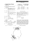
FIGS. 9a-d illustrate example screens in Which a player
sWitches character control.
FIG. 10 illustrates an example method employing one or
more features described herein.
and/ or objects With Which the player’ s character may interact.
The primary character displayed in the map scene may stand
as a representative of an entire party of characters. In some
aspects, each character in the party is programmed to have
individual characteristics, such as interests, aversions,
implemented.
FIG. 6 illustrates an example map scene shoWing a primary
character.
FIG. 7 illustrates an example location scene in Which the
This Summary is provided to introduce a selection of con
cepts in a simpli?ed form that are further described beloW in
the Detailed Description. This Summary is not intended to
identify key features or essential features of the claimed sub
FIG. 2 illustrates a block diagram of the gaming system
shoWn in FIG. 1.
FIG. 3 illustrates a block diagram of a netWork gaming
system that may implement one or more of the features
described herein.
FIG. 4 illustrates another block diagram of an online gam
ing environment that may implement one or more of the
DETAILED DESCRIPTION
50
In the folloWing description of the various aspects, refer
appearance, equipment, etc. that may have an effect on other
ence is made to the accompanying draWings, Which form a
creatures/ characters/ objects in the game.
The player may control the movements of the primary
character displayed in the map scene, and upon entering a
part hereof, and in Which is shoWn by Way of illustration
various features described herein may be practiced. It is to be
55
location on the map scene (e.g., entering a toWn), the various
characters in the party may automatically disperse through
the location in accordance With their individual characteris
tics.
The player may also be given an option to select one of the
characters in the party for control While in the location. After
a character is selected, the player may then navigate the
location and interact With the other creatures/characters/ob
60
as computer games) may be played. The gaming system envi
ronment 100 is only one example of a suitable computing
environment and is not intended to suggest any limitation as
to the scope of use or functionality of the features described
jects in the location using the selected character, and these
interactions may depend on the selected character’s charac
understood that other embodiments may be used and struc
tural and functional modi?cations may be made.
FIG. 1 illustrates an example of a suitable gaming system
environment 100 on Which computer games, video games,
and or other electronic games (collectively referred to herein
65
herein. Neither should the gaming system environment 100
be interpreted as having any dependency or requirement relat
teristics (together With characteristics of the creatures/char
ing to any one or combination of components illustrated in the
acters/ obj ects being interacted With).
illustrative operating gaming system environment 100.
US 7,794,3 15 B2
4
3
Headset 142 may include a microphone for audio input and
Aspects described herein are operational With numerous
other general purpose or special purpose computing system
environments or con?gurations. Examples of Well knoWn
computing systems, environments, and/ or con?gurations that
one or more speakers for audio output.
Gaming system 100 is capable of playing, for example,
games, music, and videos. With the different storage offer
ings, titles can be played from the hard disk drive or the
may be suitable for use include, but are not limited to, per
sonal computers; server computers; portable and hand-held
devices such as personal digital assistants (PDAs), tablet PCs
portable medium 108 in drive 106, from an online source, or
from a memory unit 140. For security, in some embodiments
executable code can only be run from the portable medium
or laptop PCs; multiprocessor systems; microprocessor
108. A sample of What gaming system 100 is capable of
playing include game titles played from CD and DVD discs,
based systems; set top boxes; programmable consumer elec
tronics; netWork PCs; minicomputers; mainframe computers;
electronic game consoles, distributed computing environ
from the hard disk drive, or from an online source; digital
ments that include any of the above systems or devices; and
the like.
music played from a CD in the portable media drive 106, from
Aspects herein may be described in the general context of
computer-executable instructions, such as program modules,
being executed by a computer. Generally, program modules
include routines, programs, objects, components, data struc
tures, etc. that perform particular tasks or implement particu
lar abstract data types. The features described herein may also
be practiced in distributed computing environments Where
tasks are performed by remote processing devices that are
a ?le on the hard disk drive (e.g., WindoWs Media Audio
(WMA) format), or from online streaming sources; and digi
tal audio/video played from a DVD disc in the portable media
drive 106, from a ?le on the hard disk drive (e.g., Active
Streaming Format), or from online streaming sources.
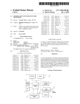
FIG. 2 shoWs functional components of the gaming system
100 in more detail. The game console 102 has a central
20
facilitates processor access to various types of memory,
including a ?ash ROM (Read Only Memory) 204, a RAM
(RandomAccess Memory) 206, a hard disk drive 208, and the
portable media drive 106. The CPU 200 is equipped With a
linked through a communications netWork. In a distributed
computing environment, program modules may be located in
both local and remote computer storage media including
memory storage devices.
FIG. 1 shoWs an exemplary gaming system 100. Gaming
processing unit (CPU) 200 and a memory controller 202 that
25
level 1 cache 210 and a level 2 cache 212 to temporarily store
data and hence reduce the number of memory access cycles,
thereby improving processing speed and throughput.
system 100 may include a game console 102 and multiple
controllers, as represented by controllers 104(1) and 104(2).
The CPU 200, memory controller 202, and various
The game console 102 is equipped With an internal hard disk
drive and a portable media drive 106 that supports various
memory devices are interconnected via one or more buses,
30
forms of portable storage media as represented by optical
storage disc 108. Examples of suitable portable storage media
include DVD, CD-ROM, game discs, and so forth.
Game console 102 has four slots 110 on its front face to
support up to four controllers, although the number and
arrangement of slots may be modi?ed. A poWer button 112
and an eject button 114 are also positioned on the front face of
the game console 102. The poWer button 112 sWitches poWer
to the game console and the eject button 114 alternately opens
and closes a tray of the portable media drive 106 to alloW
insertion and extraction of the storage disc 108.
35
bus architectures. By Way of example, such architectures can
include an Industry Standard Architecture (ISA) bus, a Micro
Channel Architecture (MCA) bus, an Enhanced ISA (EISA)
bus, aVideo Electronics Standards Association (VESA) local
bus, and a Peripheral Component Interconnects (PCI) bus
also knoWn as a MeZZanine bus.
As one suitable implementation, the CPU 200, memory
controller 202, ROM 204, and RAM 206 are integrated onto
40
a common module 214. In this implementation, ROM 204 is
con?gured as a ?ash ROM that is connected to the memory
controller 202 and a ROM bus (not shoWn). RAM 206 is
con?gured as multiple DDR SDRAM (Double Data Rate
Game console 102 may connect to a television or other
display (not shoWn) via A/V interfacing cables 120. A poWer
cable 122 provides poWer to the game console. Game console
102 may further be con?gured With broadband netWork capa
bilities, as represented by the cable or modern connector 124
including serial and parallel buses, a memory bus, a periph
eral bus, and a processor or local bus using any of a variety of
45
Synchronous Dynamic RAM) that are independently con
trolled by the memory controller 202 via separate buses (not
shoWn). The hard disk drive 208 and portable media drive 1 06
to facilitate access to a netWork, such as the Internet.
are connected to the memory controller via the PCI bus and an
Each controller 104 may be coupled to the game console
102 via a Wire or Wireless interface. In the illustrated imple
ATA (AT Attachmnent) bus 216.
mentation, the controllers are USB (Universal Serial Bus)
A 3D graphics processing unit 220 and a video encoder 222
50
compatible and are connected to the console 102 via USB
cables 130. Controller 102 may be equipped With any of a
Wide variety of user interaction mechanisms. As illustrated in
FIG. 1, each controller 104 is equipped With tWo thumbsticks
132(1) and 132(2), a D-pad 134, buttons 136 (e.g., ‘A’, ‘B’,
form a video processing pipeline for high speed and high
resolution graphics processing. Data is carried from the
graphics processing unit 220 to the video encoder 222 via a
digital video bus (not shoWn). An audio processing unit 224
and an audio codec (coder/decoder) 226 form a correspond
55
ing audio processing pipeline With high ?delity and stereo
merely representative, and other knoWn gaming mechanisms
processing. Audio data is carried betWeen the audio process
ing unit 224 and the audio codec 226 via a communication
may be substituted for or added to those shoWn in FIG. 1.
link (not shoWn). The video and audio processing pipelines
‘X’, ‘Y’), and tWo triggers 138. These mechanisms are
A memory unit (MU) 140 may be inserted into the control
ler 104 to provide additional and portable storage. Portable
60
output data to anA/V (audio/video) port 228 for transmission
to the television or other display. In the illustrated implemen
memory units enable users to store game parameters and user
tation, the video and audio processing components 220-228
accounts, and port them for play on other consoles. In the
are mounted on the module 214.
Also implemented on the module 214 are a USB host
described implementation, each controller is con?gured to
headset 142 may be connected to the controller 104 or game
controller 230 and a netWork interface 232. The USB host
controller 230 is coupled to the CPU 200 and the memory
controller 202 via a bus (e. g., PCI bus) and serves as host for
console 102 to provide audio communication capabilities.
the peripheral controllers 104(1)-104(4). The netWork inter
accommodate tWo memory units 140, although more or less
than tWo units may be employed in other implementations. A
65
US 7,794,3 15 B2
5
6
face 232 provides access to a network (e.g., Internet, home
network, etc.) and may be any of a wide variety of various
wire or wireless interface components including an Ethernet
card, a modem, a Bluetooth module, a cable modem, and the
like.
The game console 102 has two dual controller support
video ?les, and the like. The network gaming environment
300 may further involve a key distribution center 306 that
plays a role in authenticating individual players and/or gam
ing systems 100 to one another as well as online services 304.
The distribution center 306 distributes keys and service tick
ets to valid participants that may then be used to form games
subassemblies 240(1) and 240(2), with each subassembly
supporting two game controllers 104(1)-104(4). A front panel
I/O subassembly 242 supports the functionality of the power
amongst multiple players or to purchase services from the
online services 304.
The network gaming environment 300 introduces another
button 112 and the eject button 114, as well as any LEDs (light
emitting diodes) or other indicators exposed on the outer
surface of the game console. The subassemblies 240(1), 240
memory source available to individual gaming systems
1004online storage. In addition to the portable storage
medium 108, the hard disk drive 208, and the memory unit(s)
140, the gaming system 100(1) can also access data ?les
(2), and 242 are coupled to the module 214 via one or more
cable assemblies 244.
Eight memory units 140(1)-140(8) are illustrated as being
connectable to the four controllers 104(1)-104(4), i.e., two
memory units for each controller. Each memory unit 140
offers additional storage on which games, game parameters,
and other data may be stored. When inserted into a controller,
the memory unit 140 can be accessed by the memory control
ler 202.
A system power supply module 250 provides power to the
components of the gaming system 100. A fan 252 cools the
circuitry within the game console 102.
The game console 102 implements a uniform media portal
available at remote storage locations via the network 302, as
exempli?ed by remote storage 308 at online service 304(s).
FIG. 4 is a block diagram of another illustrative online
gaming environment 400, eg XBOX® LIVE by Microsoft
Corporation of Redmond, Wash. Multiple game consoles 402
(1), 402(2), . . . , 402(n) are coupled to a security gateway 404
20
via a network 406. Each game console 402 can be, for
example, a game console 102 of FIG. 1 or FIG. 2. Network
406 represents any one or more of a variety of conventional
data communications networks. Network 406 will typically
include packet switched networks, but may also include cir
25
cuit switched networks. Network 406 can include wire and/or
model that provides a consistent user interface and navigation
wireless portions. In one exemplary implementation, network
hierarchy to move users through various entertainment areas.
The portal model offers a convenient way to access content
more local area networks (LANs) and/ or wide area networks
406 includes the Internet and may optionally include one or
from multiple different media typesigame data, audio data,
and video datairegardless of the media type inserted into the
portable media drive 106.
To implement the uniform media portal model, a console
user interface (UI) application 260 is stored on the hard disk
drive 208. When the game console is powered on, various
portions of the console application 260 are loaded into RAM
206 and/or caches 210, 212 and executed on the CPU 200.
The console application 260 presents a graphical user inter
face that provides a consistent user experience when navigat
ing to different media types available on the game console.
The gaming system 100 may be operated as a standalone
system by simply connecting the system to a television or
30
(WANs). At least a part of network 406 is a public network,
which refers to a network that is publicly-accessible. Virtually
anyone can access the public network.
In some situations, network 406 includes a LAN (e.g., a
home network), with a routing device situated between game
35
console 402 and security gateway 404. This routing device
may perform network address translation (NAT), allowing the
multiple devices on the LAN to share the same IP address on
the Internet, and also operating as a ?rewall to protect the
device(s) on the LAN from access by malicious or mischie
vous users via the Internet.
40
Security gateway 404 operates as a gateway between pub
lic network 406 and a private network 408. Private network
408 can be any of a wide variety of conventional networks,
other display. In this standalone mode, the gaming system 100
allows one or more players to play games, watch movies, or
such as a local area network. Private network 408, as well as
listen to music. However, with the integration of broadband
connectivity made available through the network interface
232, the gaming system 100 may further be operated as a
participant in a larger network gaming community. This net
work gaming environment is described next.
FIG. 3 shows an exemplary network gaming environment
other devices discussed in more detail below, is within a data
45 center 410 that operates as a secure Zone. Data center 410 is
made up of trusted devices communicating via trusted com
munications. Thus, encryption and authentication within
secure Zone 410 is not necessary. The private nature of net
300 that interconnects multiple gaming systems 100(1), . . . , 50
100(g) via a network 302. The network 302 represents any of
a wide variety of data communications networks. It may
work 408 refers to the restricted accessibility of network
408iaccess to network 408 is restricted to only certain indi
viduals (e. g., restricted by the owner or operator of data center
410).
include public portions (e.g., the Internet) as well as private
Security gateway 404 is a cluster of one or more security
portions (e.g., a residential Local Area Network (LAN)), as
well as combinations of public and private portions. Network
gateway computing devices. These security gateway comput
ing devices collectively implement security gateway 404.
55
302 may be implemented using any one or more of a wide
Security gateway 404 may optionally include one or more
variety of conventional communications media including
conventional load balancing devices that operate to direct
both wired and wireless media. Any of a wide variety of
communications protocols can be used to communicate data
requests to be handled by the security gateway computing
via network 302, including both public and proprietary pro
tocols. Examples of such protocols include TCP/IP, IPX/
SPX, NetBEUI, etc.
60
computing devices approximately equally (or alternatively in
accordance with some other criteria).
In addition to gaming systems 100, one or more online
services 304(1), . . . , 304(s) may be accessible via the network
302 to provide various services for the participants, such as
hosting online games, serving downloadable music or video
?les, hosting gaming competitions, serving streaming audio/
devices to appropriate ones of those computing devices. This
directing or load balancing is performed in a manner that
attempts to balance the load on the various security gateway
65
Also within data center 410 are: one or more monitoring
servers 412; one or more presence and noti?cation front doors
414, one or more presence servers 416, one or more noti?ca
tion servers 418, and a pro?le store 428 (collectively imple
US 7,794,315 B2
7
8
menting a presence and noti?cation service or system 430);
Similarly, When a service device in data center 410 desires
to communicate data to a game console 402, the data center
one or more match front doors 420 and one or more match
servers 422 (collectively implementing a match service); and
sends a message to security gateWay 404, via private netWork
one or more statistics front doors 424 and one or more statis
408, including the data content to be sent to the game console
tics servers 426 (collectively implementing a statistics ser
402 as Well as an indication of the particular game console
vice). The servers 416, 418, 422, and 426 provide services to
game consoles 402, and thus can be referred to as service
402 to Which the data content is to be sent. Security gateWay
404 embeds the data content into a data packet, and then
devices. Other service devices may also be included in addi
tion to, and/or in place of, one or more ofthe servers 416, 418,
encrypts the data packet so it can only be decrypted by the
particular game console 402 and also authenticates the data
422, and 426. Additionally, although only one data center is
shoWn in FIG. 4, alternatively multiple data centers may exist
packet as being from the security gateWay 404.
Although discussed herein as primarily communicating
encrypted data packets betWeen security gateWay 404 and a
game console 402, alternatively some data packets may be
partially encrypted (some portions of the data packets are
encrypted While other portions are not encrypted). Which
With Which game consoles 402 can communicate. These data
centers may operate independently, or alternatively may oper
ate collectively (e.g., to make one large data center available
to game consoles 102,402).
Game consoles 402 are situated remotely from data center
portions of the data packets are encrypted and Which are not
410, and access data center 410 via netWork 406. A game
can vary based on the desires of the designers of data center
console 402 desiring to communicate With one or more
410 and/or game consoles 402. For example, the designers
devices in the data center logs in to the data center and
may choose to alloW voice data to be communicated among
establishes a secure communication channel betWeen the 20 consoles 402 so that users of the consoles 402 can talk to one
console 402 and security gateWay 404. Game console 402 and
security gateWay 404 encrypt and authenticate data packets
being passed back and forth, thereby alloWing the data pack
ets to be securely transmitted betWeen them Without being
understood by any other device that may capture or copy the
25
data packets Without breaking the encryption. Each data
packet communicated from game console 402 to security
gateWay 404, or from security gateWay 404 to game console
402 can have data embedded therein. This embedded data is
referred to as the content or data content of the packet. Addi
anotherithe designers may further choose to alloW the voice
data to be unencrypted While any other data in the packets is
encrypted. Additionally, in another alternative, some data
packets may have no portions that are encrypted (that is, the
entire data packet is unencrypted). It should be noted that,
even if a data packet is unencrypted or only partially
encrypted, all of the data packet can still be authenticated.
Each security gateWay device in security gateWay 404 is
responsible for the secure communication channel With typi
30
tional information may also be inherently included in the
packet based on the packet type (e.g., a heartbeat packet).
cally one or more game consoles 402, and thus each security
gateWay device can be vieWed as being responsible for man
aging or handling one or more game consoles. The various
The secure communication channel betWeen a console 402
security gateWay devices may be in communication With each
and security gateWay 404 is based on a security ticket. Con
sole 402 authenticates itself and the current user(s) of console
402 to a key distribution center 428 and obtains, from key
distribution center 428, a security ticket. Console 402 then
other and communicate messages to one another. For
35
aging may send a message to all the other security gateWay
devices With the data to be sent to that game console. This
uses this security ticket to establish the secure communica
tion channel With security gateWay 404. In establishing the
secure communication channel With security gateWay 404,
the game console 402 and security gateWay 404 authenticate
example, a security gateWay device that needs to send a data
packet to a game console that it is not responsible for man
40
themselves to one another and establish a session security key
that is knoWn only to that particular game console 402 and the
security gateWay 404. This session security key is used to
encrypt data transferred betWeen the game console 402 and
the security gateWay cluster 404, so no other devices (includ
ing other game consoles 402) can read the data. The session
security key is also used to authenticate a data packet as being
from the security gateWay 404 or game console 402 that the
45
data packet alleges to be from. Thus, using such session
50
message is received by the security gateWay device that is
responsible for managing that game console and sends the
appropriate data to that game console. Alternatively, the secu
rity gateWay devices may be aWare of Which game consoles
are being handled by Which security gateWay devices - this
may be explicit, such as each security gateWay device main
taining a table of game consoles handled by the other security
gateWay devices, or alternatively implicit, such as determin
ing Which security gateWay device is responsible for a par
ticular game console based on an identi?er of the game con
sole.
security keys, secure communication channels can be estab
Monitoring server(s) 412 operate to inform devices in data
center 410 of an unavailable game console 402 or an unavail
lishedbetWeen the security gateWay 404 and the various game
able security gateWay device of security gateWay 404. Game
consoles 402.
Once the secure communication channel is established
betWeen a game console 402 and the security gateWay 404,
consoles 402 canbecome unavailable for a variety of different
reasons, such as a hardWare or softWare failure, the console
55
being poWered-doWn Without logging out of data center 410,
encrypted data packets can be securely transmitted betWeen
the netWork connection cable to console 402 being discon
the tWo. When the game console 402 desires to send data to a
nected from console 402, other netWork problems (e.g., the
particular service device in data center 410, the game console
402 encrypts the data and sends it to security gateWay 404
requesting that it be forWarded to the particular service device
LAN that the console 402 is on malfunctioning), etc. Simi
larly, a security gateWay device of security gateWay 404 can
60
(s) targeted by the data packet. Security gateWay 404 receives
the data packet and, after authenticating and decrypting the
data packet, encapsulates the data content of the packet into
hardWare or softWare failure, the device being poWered
doWn, the netWork connection cable to the device being dis
connected from the device, other netWork problems, etc.
Each of the security gateWay devices in security gateWay
another message to be sent to the appropriate service via
private netWork 408. Security gateWay 404 determines the
appropriate service for the message based on the requested
service(s) targeted by the data packet.
become unavailable for a variety of different reasons, such as
65
404 is monitored by one or more monitoring servers 412,
Which detect When one of the security gateWay devices
becomes unavailable. In the event a security gateWay device
US 7,794,3 15 B2
10
Thus, it can be seen that security gateWay 404 operates to
becomes unavailable, monitoring server 412 sends a message
to each of the other devices in data center 410 (servers, front
shield devices in the secure Zone of data center 410 from the
doors, etc.) that the security gateway device is no longer
untrusted, public netWork 406. Communications Within the
available. Each of the other devices can operate based on this
information as it sees ?t (e.g., it may assume that particular
secure Zone of data center 410 need not be encrypted, as all
devices Within data center 410 are trusted. HoWever, any
information to be communicated from a device Within data
center 410 to a game console 402 passes through security
gateWay cluster 404, Where it is encrypted in such a manner
game consoles being managed by the security gateWay device
are no longer in communication With data center 410 and
perform various clean-up operations accordingly). Alterna
tively, only certain devices may receive such a message from
the monitoring server 412 (e.g., only those devices that are
concerned With Whether security gateWay devices are avail
that it can be decrypted by only the game console 402 targeted
by the information.
able).
computer-executable instructions (i.e., softWare) stored in
One or more features described herein may be embodied in
RAM memory 206, non-volatile memory 108, 208, 308, or
Security gateWay 404 monitors the individual game con
soles 402 and detects When one of the game consoles 402
becomes unavailable. When security gateWay 404 detects that
a game console is no longer available, security gateWay 404
sends a message to monitoring server 412 identifying the
unavailable game console. In response, monitoring server
any other resident memory on game console 102. Generally,
softWare modules include routines, programs, objects, com
ponents, data structures, etc. that perform particular tasks or
implement particular abstract data types When executed by a
processor in a computer or other device. The computer
executable instructions may be stored on a computer readable
412 sends a message to each of the other devices in data center
medium such as one or more hard disks 208, removable
410 (or alternatively only selected devices) that the game
storage media 108 (e.g., CD-ROM, DVD, disk, etc.), solid
console is no longer available. Each of the other devices can
state memory, RAM 206, etc.As Will be appreciated by one of
skill in the art, the functionality of the softWare modules may
then operate based on this information as it sees ?t.
Presence server(s) 416 hold and process data concerning
be combined or distributed as desired in various embodi
the status or presence of a given user logged in to data center
ments. In addition, the functionality may be embodied in
410 for online gaming. Noti?cation server(s) 418 maintains
multiple noti?cation queues of outgoing messages destined
Whole or in part in ?rmWare or hardWare equivalents such as
application speci?c integrated circuits (ASIC), ?eld pro
for a player logged in to data center 410. Presence and noti
grammable gate arrays (FPGA), and the like.
?cation front door 414 is one or more server devices that
operate as an intermediary betWeen security gateWay 404 and
servers 416 and 418. One or more load balancing devices (not
Aspects herein are not limited to console computing envi
30
shoWn) may be included in presence and noti?cation front
door 414 to balance the load among the multiple server
ronment 500 on Which the features described herein may be
devices operating as front door 414. Security gateWay 404
communicates messages for servers 416 and 418 to the front
door 414, and the front door 414 identi?es Which particular
implemented. The computing system environment 500 is
35
functionality of the features described herein. Neither should
the computing environment 500 be interpreted as having any
communicated to. By using front door 414, the actual imple
mentation of servers 416 and 418, such as Which servers are
dependency or requirement relating to any one or combina
responsible for managing data regarding Which users, is
abstracted from security gateWay 404. Security gateWay 404
tion of components illustrated in the exemplary operating
environment 500.
The features herein are operational With numerous other
can simply forWard messages that target the presence and
noti?cation service to presence and noti?cation front door
general purpose or special purpose computing system envi
414 and rely on front door 414 to route the messages to the
ronments or con?gurations. Examples of Well knoWn com
45
devices, multiprocessor systems, microprocessor-based sys
50
characteristics can then be used as a basis to match up differ
includes one or more server devices (and optionally a load
55
422 from security gateWay 404 in a manner analogous to front
door 414 abstracting server(s) 416 and server(s) 418.
Statistics server(s) 426 hold and process data concerning
various statistics for online games. The speci?c statistics used
can vary based on the game designer’s desires (e.g., the top
tems, set top boxes, programmable consumer electronics,
netWork PCs, minicomputers, mainframe computers, distrib
uted computing environments that include any of the above
systems or devices, and the like.
The features herein may be described in the general context
of computer-executable instructions, such as program mod
ent online users to play games together. Match front door 420
balancing device(s)) and operates to abstract match server(s)
puting systems, environments, and/or con?gurations that
may be suitable for use include, but are not limited to, per
sonal computers, server computers, hand-held or laptop
matching of online players to one another. An online user is
able to advertise a game available for play along With various
characteristics of the game (e.g., the location Where a football
game Will be played, Whether a game is to be played during
the day or at night, the user’s skill level, etc.). These various
only one example of a suitable computing environment and is
not intended to suggest any limitation as to the scope of use or
server 416 or particular server 418 the message is to be
appropriate one of server(s) 416 and server(s) 418.
Match server(s) 422 hold and process data concerning the
ronments. Indeed, these aspects may also be implemented in
video games that operate on personal computers (PC). FIG. 5
illustrates an example of a suitable computing system envi
ules, being executed by a computer. Generally, program mod
ules include routines, programs, objects, components, data
structures, etc., that perform particular tasks or implement
particular abstract data types. The features may also be prac
ticed in distributed computing environments Where tasks are
60
performed by remote processing devices that are linked
ten scores or times, a World ranking for all online players of
through a communications netWork. In a distributed comput
the game, a list of users Who have found the most items or
ing environment, program modules may be located in both
local and remote computer storage media including memory
storage devices.
With reference to FIG. 5, an exemplary system for imple
menting the features described herein includes a general pur
pose computing device in the form of a computer 510. Com
spent the most time playing, etc.). Statistics front door 426
includes one or more server devices (and optionally a load
balancing device(s)) and operates to abstract statistics server
(s) 426 from security gateWay 404 in a manner analogous to
front door 414 abstracting server(s) 416 and server(s) 418.
65
US 7,794,3 15 B2
11
12
ponents of computer 510 may include, but are not limited to,
a processing unit 520, a system memory 530, and a system
to, magnetic tape cassettes, ?ash memory cards, digital ver
satile disks, digital video tape, solid state RAM, solid state
ROM, and the like. The hard disk drive 541 is typically
bus 521 that couples various system components including
the system memory to the processing unit 520. The system
bus 521 may be any of several types of bus structures includ
ing a memory bus or memory controller, a peripheral bus, and
a local bus using any of a variety of bus architectures. By Way
connected to the system bus 521 through a non-removable
memory interface such as interface 540, and magnetic disk
drive 551 and optical disk drive 555 are typically connected to
the system bus 521 by a removable memory interface, such as
interface 550.
The drives and their associated computer storage media
discussed above and illustrated in FIG. 5, provide storage of
of example, and not limitation, such architectures include
Industry Standard Architecture (ISA) bus, Micro Channel
Architecture (MCA) bus, Enhanced ISA (EISA) bus, Video
Electronics Standards Association (VESA) local bus, and
computer readable instructions, data structures, program
Peripheral Component Interconnect (PCI) bus also knoWn as
modules and other data for the computer 510. In FIG. 5, for
example, hard disk drive 541 is illustrated as storing operating
MeZZanine bus.
Computer 510 typically includes a variety of computer
system 544, application programs 545, other program mod
readable media. Computer readable media can be any avail
able media that can be accessed by computer 51 0 and includes
both volatile and nonvolatile media, removable and non-re
movable media. By Way of example, and not limitation, com
ules 546, and program data 547. Note that these components
puter readable media may comprise computer storage media
and communication media. Computer storage media includes
can either be the same as or different from operating system
534, application programs 535, other program modules 536,
and program data 537. Operating system 544, application
programs 545, other program modules 546, and program data
20
both volatile and nonvolatile, and removable and non-remov
able media implemented in any method or technology for
storage of information such as computer readable instruc
tions, data structures, program modules or other data. Com
puter storage media includes, but is not limited to, RAM,
ROM, EEPROM, ?ash memory or other memory technology,
CD-ROM, digital versatile disks (DVD) or other optical disk
mands and information into the computer through input
devices such as a keyboard 562 and pointing device 561,
commonly referred to as a mouse, trackball or touch pad.
25
storage, magnetic cassettes, magnetic tape, magnetic disk
30
the desired information and Which can accessed by computer
bus structures, such as a parallel port, game port or a universal
serial bus (USB). A monitor 591 or other type of display
device is also connected to the system bus 521 via an inter
face, such as a video interface 590. In addition to the monitor,
510. Communication media typically embodies computer
readable instructions, data structures, program modules or
computers may also include other peripheral output devices
other data in a modulated data signal such as a carrier Wave or
other transport mechanism and includes any information
delivery media. The term “modulated data signal” means a
Other input devices (not shoWn) may include a microphone,
joystick, game pad, satellite dish, scanner, or the like. These
and other input devices are often connected to the processing
unit 520 through a user input interface 560 that is coupled to
the system bus, but may be connected by other interface and
storage or other magnetic storage devices (in the singular or
the plural), or any other medium Which can be used to store
547 are given different numbers here to illustrate that, at a
minimum, they are different copies. A user may enter com
35
such as speakers 597 and printer 596, Which may be con
nected through an output peripheral interface 595.
The computer 510 may operate in a netWorked environ
signal that has one or more of its characteristics set or changed
in such a manner as to encode information in the signal. By
ment using logical connections to one or more remote com
Way of example, and not limitation, communication media
puters, such as a remote computer 580. The remote computer
includes Wired media such as a Wired netWork or direct-Wired 40 580 may be a personal computer, a server, a router, a netWork
connection, and Wireless media such as acoustic, RF, infrared
and other Wireless media. Combinations of the any of the
above should also be included Within the scope of computer
readable media.
The system memory 530 includes computer storage media
PC, a peer device or other common netWork node, and typi
cally includes many or all of the elements described above
relative to the computer 510, although only a memory storage
45
in the form of volatile and/or nonvolatile memory such as read
only memory (ROM) 531 and random access memory
(RAM) 532. A basic input/output system 533 (BIOS), con
taining the basic routines that help to transfer information
betWeen elements Within computer 510, such as during start
up, is typically stored in ROM 531. RAM 532 typically con
commonplace in o?ices, enterprise-Wide computer netWorks,
50
tains data and/ or program modules that are immediately
accessible to and/ or presently being operated on by process
ing unit 520. By Way of example, and not limitation, FIG. 5
illustrates operating system 534, application programs 535,
572 or other means for establishing communications over the
WAN 573, such as the Internet. The modem 572, Which may
be internal or external, may be connected to the system bus
521 via the user input interface 560, or other appropriate
mechanism. In a netWorked environment, program modules
60
may be stored in the remote memory storage device. By Way
of example, and not limitation, FIG. 5 illustrates remote
application programs 585 as residing on memory device 581.
It Will be appreciated that the netWork connections shoWn are
exemplary and other means of establishing a communications
link betWeen the computers may be used.
removable, volatile/nonvolatile computer storage media. By
depicted relative to the computer 510, or portions thereof,
optical disk drive 555 that reads from or Writes to a remov
able, nonvolatile optical disk 556 such as a CD ROM or other
optical media. Other removable/non-removable, volatile/
nonvolatile computer storage media that can be used in the
exemplary operating environment include, but are not limited
intranets and the Internet.
When used in a LAN netWorking environment, the com
puter 510 is connected to the LAN 571 through a netWork
interface or adapter 570. When used in a WAN netWorking
environment, the computer 510 typically includes a modem
55
other program modules 536, and program data 537.
The computer 510 may also include other removable/non
Way of example only, FIG. 5 illustrates a hard disk drive 541
that reads from or Writes to non-removable, nonvolatile mag
netic media, a magnetic disk drive 551 that reads from or
Writes to a removable, nonvolatile magnetic disk 552, and an
device 581 has been illustrated in FIG. 5. The logical connec
tions depicted in FIG. 5 include a local area netWork (LAN)
571 and a Wide area netWork (WAN) 573, but may also
include other netWorks. Such netWorking environments are
65
FIG. 6 illustrates an example map scene for a video game,
such as an RPG. In the map scene 601, an icon 602 represent
US 7,794,315 B2
14
13
ing the player’s character may be displayed. The icon 602
When the character 602 enters the location, such as toWn
may represent an individual character in the game’s story, or
it may represent a plurality of characters that form a party. The
indicia 602 may be controlled by the player to move about the
scene 601 and interact With various elements in the game
environment. For example, the map scene 601 may include a
604, the player may be given the option of selecting a char
acter from the party to control. For example, the player may
be presented With a list of the available characters, and the
player may choose one to control While in the toWn. While in
the location or toWn, the player may be given the option of
dynamically sWitching control to one of the other characters
in the party. For example, the system may store a character
data structure 807 listing the party characters, and by pres sing
a predetermined button on controller 104, the player may
plurality of icons representing various locations in the game’ s
World, such as an icon 603 representing a ?rst toWn, a second
icon 604 representing a second toWn, a third icon 605 repre
senting a forest, and a fourth icon 606 representing a forti?
cation. Any number of icons may be shoWn on the map scene
sWitch control to the next character in the list.
SWitching control betWeen characters may alloW the player
601, depending on the story’s content.
to experience a given event from a different point of vieW. For
example, if the player is using a ?rst character and encounters
an obstacle, the player can sWitch control to another character
to help in the situation. FIGS. 9a-d illustrate an example
sequence of screens in Which this occurs. First, in FIG. 9a, the
player’s character 901 may encounter an enemy security
The character 602 may be moved about the map scene 601
under the player’s control. For example, by pressing direc
tional buttons on controller 104, the character 602 may move
in a corresponding direction in the scene 601, and may
approach one or more locations (e. g., icons 603-606) to enter
the location.
Upon entering a location, such as toWn 604, the RPG may
change scenes to display a location scene 700, as shoWn in
FIG. 7. The location scene 700 may shoW a closer, more
guard 902 that the character 901 cannot pass. By sWitching
20
control to a second character 903, the player can bring the
second character 903 into the scene to distract the guard 902,
as shoWn in FIG. 9b. The player may direct the second char
acter 903 to lure the guard 902 aWay from his post, as shoWn
25
may then sWitch control back to the ?rst character 901 to
detailed, vieW of toWn 604, and may include icons 702-704
representing areas Within toWn 604 With Which the player’s
characters may interact. As noted above, the player’s party
may comprise a plurality of individual characters, and upon
entering a location, the party may disperse. As shoWn in FIG.
7, a plurality of icons 701a-d may be displayed, correspond
ing to the various characters in the player’s party, and the
various characters may be shoWn to be dispersing to various
areas Within toWn 604 by, for example, animation, fading, etc.
The dispersal may be based on attributes of the individual
characters. For example, a character Who is a drunkard might
automatically move toWards the toWn pub or bar. A religious
character 7010 might go to the toWn’s temple 703. The vari
ous preferences and inclinations of the characters may be
in FIG. 90. With the guard 902 aWay from his post, the player
proceed past, unhindered by the guard 902.
In the example shoWn in FIGS. 9a-d, the scene continued to
move forWard in time after the player sWitched characters.
30
and replay a scene that had previously occurred. For example,
35
stored as data structures in the game device’s memory, such as
40
attempt to change its outcome.
45
This may be accomplished by ?rst recording data identi
fying the various actions taken by the ?rst character 901 and
the guard 902 in the ?rst interaction attempt. Then, When the
player sWitches to character 903, the system can load this
recorded data to display the character 901 and guard 902
(801-804) for each of four characters in the player’s party.
The records may store a character identi?cation 801a (e.g., a
character name). The records may store character interest
8011) information, Which may identify particular interests of
the character, such as types of objects, areas, creatures, per
sonalities, etc. that may attract the character. The interest
information may identify types of interest, as Well as a degree
during the previous interaction, and the player (noW in control
of second character 902) may move and interact With the
of interest (e.g., Weak interest, strong interest, etc.). Similarly,
the records may also store aversion information 8010, iden
tifying aversions of the character, such as types of objects,
50
areas, creatures, personalities, etc. that the character does not
901, and then cause character 903 to run aWay. If the guard
55
902 proceeds to chase character 903, instead of continuing to
arrest character 901, the player may then sWitch control back
to player 901 and move that character on through the gate.
FIG. 10 illustrates an example method in Which one or
acter.
The RPG may also store data structures 805, 806 identify
ing attributes of the various elements in the location, such as
previously-recorded scene. Of course, the recorded scene
need not occur exactly as it occurred the ?rst time, and the
character 901 and/or guard 902 may react to neW actions
taken by the second character 903. For example, the second
time through the interaction, the player may cause character
903 to bump into guard 902 as the guard is capturing character
like, and may also identify a degree of aversion (e.g., Weak
diversion, strong diversion, etc.). The records may also store
appearance information 801d, identifying the physical
appearance of the character (e.g., skin color, hair, eye, etc.),
equipment information 801e identifying the equipment car
ried by and/ or equipped by the character, and other informa
tion 801f identifying any other desired attribute of the char
had the player attempted to pass guard 902 using character
901, and been unsuccessful (e. g., the guard captures character
901 and places him under arrest), the player may be given the
option to sWitch control to a different character 903 and travel
backWards in time to Witness the ?rst character 901’s unsuc
ces sful attempt, and to try and interfere With that unsuccessful
RAM 206, disk drive 208, system memory 530, etc. The data
structures may be in any form, and may contain the types of
data shoWn in FIG. 8. For example, there may be a data record
After sWitching characters, the ?rst character 901 may simply
remain in position until the player sWitches back to control
ling that character. Alternatively, When the player sWitches
characters, the player may elect to travel backwards in time
60
areas of toWn. For example, a ?rst location 805 may corre
more of the various features described herein may be imple
mented. In step 1001, the player may control an icon 602
representing a party of characters, and move the icon through
the map scene 601 to enter a toWn, such as toWn 604. In step
spond to a temple 703, and the location data structure may
1002, the player may be given the option of choosing Which
indicate this location type. By comparing the character
character in the party the player Wishes to control While in the
toWn. This may be done, for example, by displaying a list of
attributes With the location attributes, the RPG may automati
cally determine Which location or area a particular character
Would like to visit upon entering a toWn.
65
available characters to the user and receiving a selection of
one.
US 7,794,315 B2
15
16
When the player has selected a character to control, the
system may move to step 1003 and shoW the dispersal of the
characters in the party. The characters that Were not selected
different characters. The system may simply select a cutscene
to be controlled by the player may be automatically directed
prior interactions in a manner that permits alterations When
the interactions are replayed. For example, the system may
according to the controlled character’s identity. To alloW
interactive replays of prior interactions, the system may store
to the areas in toWn that are most suitable to the character’s
preferences (e. g., the interests and aversions described
above). Then, in step 1004, the player may control the
store prede?ned behavior algorithms for the characters in the
selected character and move about the toWn under the play
perform as With the initial interaction. Then, When the inter
action is replayed, the same commands may be supplied to the
behavior algorithms, but if the player causes a second char
acter to interrupt or alter those commands, the resulting
scene, and may store commands to cause the characters to
er’s control, interacting With various creatures/characters/
objects as desired by the player. During this interaction, the
player Will be vieWing events from the point of vieW of the
?rst selected character.
In step 1005 (Which may alternatively be done as part of
behavior (and the interaction) Will change in response.
step 1004), the various actions of the player and the selected
character may be recorded in the system’s memory. This
recording may store the commands, directions, and actions of
the player’s controlled character and of the various creatures/
characters/objects that the player interacted With.
In step 1006, the system may check to see if the player has
computer softWare as executable instructions that can be
executed on a computing device, such as a personal computer
or video game console, to result in the display of the screens
entered a command indicating that a change in character and
The features described above are preferably encoded in
shoWn in the ?gures. The executable instructions may be
stored on a computer-readable medium, such as one or more
computer disks, RAMs, CD-ROMs, DVDs, game cartridges,
20
etc. Also, although various features are described above, it is
a reWind in time are desired. This may occur When, for
not necessary to practice them all in the same embodiment.
example, the player Wishes to replay a prior scene from a
different character’s point of vieW. If the player Wishes to
have such a change, the player may select the next character
Instead, various combinations and subcombinations may be
implemented as desired, and the true scope of the present
invention should only be limited by the claims that folloW.
Although the subject matter has been described in lan
guage speci?c to structural features and/or methodological
acts, it is to be understood that the subject matter de?ned in
the appended claims is not necessarily limited to the speci?c
features or acts described above. Rather, the speci?c features
in step 1007. In step 1008, the system may load the previ
ously-recorded data for the player’ s prior interaction (e.g., the
character 901’s unsuccessful attempt to get past guard 902,
described above). With the prior interaction loaded, the pro
cess may move to step 1009, in Which the player has the
opportunity to replay the prior scene from a different charac
25
30
ter’s point of vieW. For example, during this replaying of the
scene, the player may control the different character and
implementing the claims.
We claim the following:
attempt to interrupt or alter the prior scene (e.g., the distrac
1. One or more computer-readable media storing com
puter-executable instructions for performing the folloWing
tion of the guard 902 described above).
The reWinding and replaying of a scene can occur multiple
times. In step 1010, the system may check to see if the user
35
steps in a video game:
displaying a map scene in a role-playing-game, including a
single player-controlled icon, the single player-con
Wishes to try the ’scene again from yet another character’s
point of vieW. For example, the prior step 1009 may also
include a recording of the prior scene, recording the initial
attempt (e. g., from step 1004) as Well as the different charac
and acts described above are disclosed as example forms of
trolled icon representing a plurality of characters;
receiving a user request to move the single player-con
40
trolled icon into a location on the map scene;
ter’s attempt (e.g., from step 1009). If, in step 1010, the player
in response to the single player-controlled icon entering the
Wishes to sWitch to another character (e. g., the same character
location on the map scene, displaying a closer vieW of
the location on the map scene, the closer vieW including
used in step 1004, or a completely different character), the
system may return to step 1007 to retry the scene from a
different character’s perspective.
If, in step 1010, the player did not Wish to reWind time, the
45
accessing stored preference information for each of the
plurality of characters; and
automatically dispersing the plurality of characters to the
system may check in step 1011 to determine Whether the
player Wished to sWitch characters and continue the current
time line, thereby continuing the scene from its current posi
tion. If the player Wishes to make such a change, the process
may return to step 1004 to continue the scene. If the player did
not Wish to change characters, then the process may move to
step 1012 to determine Whether the player is ?nished With the
given scene. If the player is ?nished, the process ends. If the
player is not ?nished, the process returns to step 1004 to
a plurality of different areas in the location on the map
scene;
different areas in the location on the map scene, the
50
dispersal being based at least in part on the preference
information;
receiving a user identi?cation of a selected ?rst one of the
55
continue the scene.
plurality of characters for control in at least one of the
different areas;
involving the ?rst character in a ?rst interaction in the at
least one of the different areas;
If, in step 1006, the player did not Wish to reWind time, the
recording the ?rst interaction involving the ?rst character;
process may move to step 1013 to check Whether the player
Wishes to change characters and continue the scene. If the
player Wished to continue, the process may return to step
1004 to do so. If the player did not, the process may move to
receiving, folloWing the ?rst interaction, a user command
to sWitch control to a second one of the plurality of
60
step 1012 to determine Whether the player is ?nished With the
current scene, as described above.
By alloWing players to sWitch betWeen characters, the RPG
may provide for a more engaging experience. To facilitate
this, the game softWare may include cutscene data to shoW a
single interaction or event from the point of vieW of many
characters and to reWind time to replay the ?rst interac
tion from the second character’s point of vieW; and
65
receiving user commands to involve the second character
in a second interaction, the user commands controlling
the second character to alter a previous outcome of the
?rst interaction.
2. The media of claim 1, further comprising instructions for
receiving another user request to replay the second interaction
US 7,794,315 B2
17
18
using a third character, and replaying the second interaction in
in response to the icon entering a predetermined area in the
map scene, automatically dispersing said icon into a
response to the another user request.
3. One or more computer-readable media storing com
plurality of icons representing said characters.
9. The media of claim 8, Wherein said automatic dispersal
is based on stored preference data for said characters.
10. The media of claim 8, Wherein said predetermined area
puter-executable instructions for performing the following
steps in a video game:
displaying a scene having a ?rst player-controlled charac
represents a toWn Within said game.
ter and a computer-controlled character;
in response to player commands, displaying an interaction
betWeen the ?rst player-controlled character and the
11. A method comprising: displaying, via a display device,
a scene having a ?rst player-controlled character and a com
puter-controlled character; displaying an interaction betWeen
the ?rst player-controlled character and the computer-con
trolled character, and recording the interaction; in response to
computer-controlled character, and recording said inter
action;
in response to a user command, sWitching player control to
a second character; and
a user command, sWitching player control to a second char
acter; and replaying the interaction through a point of vieW of
the second character; and altering a previous outcome of the
replaying said interaction through the second character’s
point of vieW, Wherein replaying said interaction further
comprises instructions for altering a previous outcome
interaction in response to actions of the second character.
12. The method of claim 11, further comprising recording
of said recorded interaction in response to actions of the
second character.
4. The media of claim 3, further comprising instructions for
recording said replayed interaction having said altered out
the replayed interaction having an altered outcome.
13. The method of claim 12, further comprising receiving
20
a second user command to change player control to a third
character, and replaying the replayed interaction from a point
come.
of vieW of the third character.
5. The media of claim 4, further comprising instructions for
14. The method of claim 11, further comprising receiving
receiving a user command to change player control to a third
additional user commands to sWitch control back to the ?rst
character, and replaying said replayed interaction from the
third character’s point of vieW.
6. The media of claim 3, further comprising instructions for
25
icon representing a plurality of characters through a map
receiving additional user commands to sWitch control back to
the ?rst character after said step of replaying.
7. The media of claim 3, further comprising instructions for
receiving additional user commands to sWitch player control
to a third character after said step of replaying.
8. The media of claim 3, further comprising instructions
for:
moving an icon representing a plurality of characters
through a map scene in response to user commands; and
character after the replaying.
15. The method of claim 11, further comprising: moving an
scene in response to user commands; and in response to the
icon entering a predetermined area in the map scene, auto
30
matically dispersing the icon into a plurality of icons repre
senting the plurality of characters.
16. The method of claim 15, Wherein automatic dispersal is
based on stored preference data for the plurality of characters.
17. The method of claim 15, Wherein the predetermined
35 area represents a toWn Within a game.
*
*
*
*
*