1
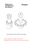
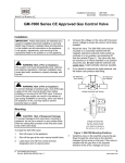
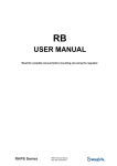
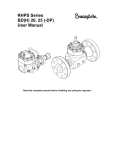
RHPS Series LPRD4,6,8 -DP User Manual Read the complete manual before installing and using the regulator. Only available through authorized Swagelok sales and service representatives. Contents Introduction ............................................................................................................................................... 3 Installation ................................................................................................................................................. 4 Operation ................................................................................................................................................... 5 Maintenance .............................................................................................................................................. 6 Troubleshooting ........................................................................................................................................ 9 Only available through authorized Swagelok sales and service representatives. 2 Introduction Representative drawing of the standard LPRD4,6,8 -A-DP and its components 1 Body assembly 13 Set spring 24 Ball 3 Poppet balancing O-ring 14 Poppet spring 27 Fitting O-ring 4 Poppet balancing back-up ring 15 Diaphragm screw 28 Spring housing O-ring 5 Anti-tamper cap 16 Diaphragm plate 29 Seal ring 6 Anti-tamper cap O-ring 17 Set screw 30 Spring guide O-ring 7 Body plug 18 Diaphragm 33 Nut 8 Poppet O-ring 19 Seat O-ring 34 Top cover 9 Poppet housing 20 Body plug O-ring 35 Spring housing 10 Poppet stem 21 Ring 36 Fitting (dome connection) 11 Seat 22 Nut 12 Spring guide 23 Socket head cap screw Only available through authorized Swagelok sales and service representatives. 3 Installation WARNING Self-venting and captured-venting regulators can release system fluid to atmosphere. Position the self-venting hole or the captured vent connection away from operating personnel WARNING The working pressure of the diaphragm enclosed is 232 psig (16 bar). Do not exceed a downstream pressure of 232 psig (16 bar). CAUTION Do not use the regulators as a shutoff device. CAUTION Because dome pressure is higher than the outlet pressure, place a gauge on the outlet line to set or check the outlet pressure. The preferred mounting position of the regulator is horizontal with the spring housing facing upwards. An upstream filter is recommended for use in all but the cleanest of media. The standard connection of the LPRD4,6,8 DP is bspp parallel female. To get a proper sealing across the thread, Swagelok recommends using bonded seal rings. If grounding is required, connect the ground wire under a top cover bolt. Install a downstream pressure relief valve for regulator and system protection. Only available through authorized Swagelok sales and service representatives. 4 Operation Points of attention before operation CAUTION Do not use the regulators as a shutoff device. A decrease in the inlet pressure will result in a rise of the outlet pressure. This phenomenon is usually referred to as the “dependency” and does not indicate a problem with the regulator. An increase in the flow will result in a fall of the outlet pressure. This phenomenon is usually referred to as the “droop” and does not indicate a problem with the regulator. If the shut-off valve at the outlet side is closed after changing the set pressure, the outlet pressure will rise a little because of the closing force required for bubble-tight closing of the regulator. This phenomenon is usually referred to as the “lock-up” and does not indicate a problem with the regulator. After flow, the inlet pressure will decrease a little under the set pressure. This is because of the closing force required for bubble-tight closing of the regulator. This phenomenon is usually referred to as the “reseat pressure” and does not indicate a problem with the regulator. Changing the differential set pressure Set the outlet pressure by filling the dome. Use the set screw to fine tune the outlet pressure (clockwise to increase, counterclockwise to decrease). Final adjustment must be made while increasing the differential set pressure to obtain the most accurate set point(s). Pressurizing the Dome Manually: Control the pressure manually by taking the gas pressure from a cylinder or main line, through a spring-loaded pilot regulator, and into the dome. Electronically: Control the pressure electronically using a proportional control valve and a pressure sensor in place of the spring-loaded pilot regulator. For the best result, use an accurate, self-venting pilot regulator. Only available through authorized Swagelok sales and service representatives. 5 Maintenance WARNING Before servicing any installed regulator you must depressurize the system and dome cycle the regulator purge the regulator CAUTION Only tighten the bolts or components when the regulator is depressurized. Required tools for maintenance a vice to fasten the regulator pincers to take out the O-rings a torque wrench a torque wrench hexagon head key 5 a torque wrench hexagon head key 6 a torque wrench “open end insert tool”, 19 mm a socket head, 24 mm an open end wrench, 50 mm media and temperature compatible lubricant for reassembling threaded parts media and temperature compatible lubricant for O-rings ® Snoop liquid leak detector lubricate threaded components to avoid galling of the threads lubricate O-rings to promote service life and performance test the regulator for proper operation Only available through authorized Swagelok sales and service representatives. 6 Removal from the system Isolate the regulator from all pressure sources by closing the appropriate valves in the system. Turn the adjustment knob/setscrew counterclockwise to decrease the set pressure. Make sure that the inlet and outlet pressure are both reduced to zero. Make sure that the dome pressure is reduced to zero. A shut-off valve on the outlet side must be opened to relief the pressure on the outlet side. Disassembly instructions Loosen the hexagon socket head screws and remove the dome, spring and spring guide. Also remove the diaphragm and diaphragm plate, together with the diaphragm screw. Loosen the body plug and remove the poppet, poppet spring, and seat. Inspection of disassembled parts Check all parts for abnormal wear. Replace parts in case of doubt. Points of attention before assembly Lubricate threaded components to avoid galling of the threads. Lubricate O-rings to promote service life and performance. Test the regulator for proper operation. Assembly instructions Follow the points for disassembly in reverse order to assemble the regulator. Only available through authorized Swagelok sales and service representatives. 7 Recommended torques CAUTION Only tighten the bolts or parts if the regulator is completely depressurized. - Hexagon socket head screws M6 Spring housing Body plug Fitting (dome connection) 10 N·m (88 in.·lb) 100 N·m (885 in.·lb) 20 N·m (177 in.·lb) 20 N·m (177 in.·lb) Only available through authorized Swagelok sales and service representatives. 8 Troubleshooting Problem: Cause: Solution: Leakage around the body plug. A damaged O-ring or back-up ring or both. Replace the O-ring or back-up ring or both. Tighten the body plug according to the recommended torque. Problem: Cause: Solution: The outlet pressure slowly increases, without increasing the dome pressure. A damaged valve or seat or both. Replace the valve or the seat or both. Problem: Cause: The outlet pressure has changed without adjusting the dome pressure. Changes to the inlet pressure result in changes to the outlet pressure. A decrease in the inlet pressure results in an increase in the outlet pressure. An increase in the inlet pressure results in a decrease in the outlet pressure. Maintain a constant regulator inlet pressure. See “dependency” in section 3, Operation. Solution: Problem: Cause: Solution: Problem: Cause: Solution: Problem: Cause: Solution: The required outlet pressure can not be reached. The regulator inlet pressure is not high enough. The inlet pressure to the dome regulator or to the pilot regulator is not high enough. Make sure the regulator inlet pressure is high enough Make sure that the inlet pressure to the dome regulator and to the pilot regulator is high enough. Leakage between the top cover and the spring housing. A damaged diaphragm Insufficient torque on the cap screws. Replace the diaphragm and spring guide O-ring. Tighten the cap screws to the recommended torque. Leakage between the set screw and the spring housing. A damaged diaphragm and spring guide O-ring Insufficient torque on the cap screw Replace the diaphragm and spring guide O-ring. Tighten the cap screws to the recommended torque. Problem: Cause: Solution: Outlet pressure drops off sharply even when the flow is within regulator capabilities. The upstream filter or the regulator’s inlet filter has an obstruction. Replace the obstructed filter element or elements. Problem: Cause: Solution: The outlet pressure rises above the set pressure at high flow. The flow rate is higher than stated in the product catalog. A larger regulator is required. Problem: Cause: Solution: The outlet pressure has changed without adjusting the regulator. Changes to the inlet pressure result in changes to the outlet pressure. A decrease in the inlet pressure results in an increase in the outlet pressure. An increase in the inlet pressure results in a decrease in the outlet pressure. Maintain a constant regulator inlet pressure. See “dependency” in section 3, Operation. Problem: Cause: Solution: The required outlet pressure can not be reached. The regulator inlet pressure is not high enough. Make sure the regulator inlet pressure is high enough. Problem: Cause: The outlet pressure increases without adjusting the regulator. A damaged valve or seat or both. The regulator is mounted in the wrong orientation. Replace the relief seat or O-ring or both. Mount the regulator in the correct orientation. Solution: Only available through authorized Swagelok sales and service representatives. 9 Problem: Cause: Solution: The outlet pressure does not decrease when adjusted to decrease the pressure. The regulator is non-self-venting. Open a downstream shutoff valve to reduce the outlet pressure. Warranty Information Swagelok products are backed by The Swagelok Limited Lifetime Warranty. For a copy, visit swagelok.com or contact your authorized Swagelok representative. For additional information, see www.swagelok.com. Caution: Do not mix or interchange parts with those of other manufacturers. Swagelok, Snoop – Swagelok Company © 2011 Swagelok Company May 2011, R0 MS-CRD-0192 Only available through authorized Swagelok sales and service representatives.