1
UPP2-X Portable in Circuit Programmer with GLCD
The included USB cable must be connected to a free USB connector of the PC. The USB drivers must be
installed once in order to work properly. See the USB section at the end of this manual.
The internal voltage is 3.3Volt. Don’t apply high loads at the target pins used for programming. No capacitors
are allowed at these pins. Capacitance at the RESET pin must not exceed 100nF.
With XMegas there must be no capacitor connected to the Reset pin. Pullup minimum 100kOhm.
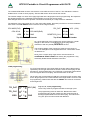
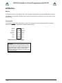
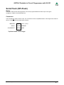
The definition of the 6-pin target plug (0.1 inch pitch male header, dual inline) conforms to a recommendation
from Atmel. The TOP VIEW onto the connector of the Target is below:
CPU MISO(TxD)
o1 2o
VCC
CPU SCLK
o3 4o
CPU MOSI(RxD)
o5 6o
GND
/RES
PDI_DAT
VCC (3.3V)
o3 4o
RESET/PDI_CLK
Top View AVR SPI header
o1 2o
o5 6o
GND
Top View XMEGA PDI header
Pin1 of the 6pin plug of the programmer can be located by a small
triangle on the front of it. A misalignment of the plug leads to
malfunction and can possibly DESTROY the unit.
The working voltage of the Target CPU must be in the range of
1.8V..5.5V. XMegas must be supplied with max. 3.6V and the TINYs
not below 5.0V.
None of the 4 control lines of the device must be shorted. A
continuous short circuit can destroy the programmer. Only
electrically tested boards should be connected.
JTAG programming
For JTAG programming of the target CPU the 6-wire ribbon cable must be
replaced by 10-wire type. Because the UPP2-X uses the same plug for ISP
and also for JTAG programming, the JTAG plug on the target system differs
from the original Atmel JTAG plug. See the schematic on the left.
On the left is the recommended E-LAB plug connection which must be used
for the target system if the JTAG interface of the target AVR is to be be used
for programming. Please note that also the /RESET line must be connected
to the target CPU.
TPI_DAT
1 2
TPI_CLK
3 4
/RES
5 6
4 · Connections
VCC (5V)
Tiny 4, 5, 9, 10, 20 programming
These Tinys must be programmed with 5V through 3 pins.
GND
The programming mode is called TPI. Because the same
programming plug is also used by the SPI mode the plug on
the target system differs from the Atmel plug. The load on the
TPI_DAT pin must not be lower than 80kOhm.
E-LAB Computers