1
RoboPi v1.00
User Manual v0.85
Copyright 2014 William Henning
Using RoboPi
Copyright 2014 William Henning
RoboPi User Manual v0.85
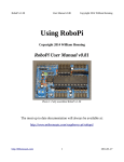
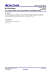
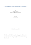
Photo 1: Fully assembled RoboPi v1.00
The most up to date documentation will always be available at:
http://www.mikronauts.com/raspberry-pi/robopi/
http://Mikronauts.com
1
2014-01-27
RoboPi v1.00
User Manual v0.85
Copyright 2014 William Henning
Table of Contents
Introduction................................................................................................................................................4
RoboPi Printed Circuit Board....................................................................................................................5
RoboPi I/O Pin Definitions........................................................................................................................6
P0-P7: SERVO 1 – SERVO 8................................................................................................................6
P8-P15: SERVO 9 – SERVO 16............................................................................................................6
P16-P23: SENSOR 1 – SENSOR 8......................................................................................................6
P24-P27: SPI port for MCP3008/MCP3208.........................................................................................6
ADC1-ADC8: 0-5V Analog inputs.......................................................................................................6
RoboPi Expansion Connectors...................................................................................................................7
Raspberry Pi I/O header pins.................................................................................................................7
EXP1/EXP2/EXP3 3v3 Expansion Connectors....................................................................................7
PI-I2C Header........................................................................................................................................7
PROP-I2C Header.................................................................................................................................7
PROPPLUG Header..............................................................................................................................7
Using RoboPi with the Raspberry Pi.........................................................................................................8
Downloading & Installing Raspbian (Debian for the Pi)......................................................................8
Step 1: Get a compatible Class 10 speed SD card, 8GB – 32GB in size..........................................8
Step 2: Download the latest Raspbian image...................................................................................8
Step 3: Install Raspbian....................................................................................................................8
Step 4: Using the Raspberry Pi serial port with RoboPi...................................................................9
Step 5: Installing RoboPiLib..........................................................................................................10
Step 6: Installing the RoboPi Firmware..........................................................................................10
Step 7: Installing SimpleIDE for the Raspberry Pi (OPTIONAL).................................................10
Introducing RoboPiLib.............................................................................................................................11
Python RoboLib Constants..................................................................................................................13
Python RoboPiLib Functions..............................................................................................................13
C RoboPiLib Constants......................................................................................................................14
C RoboPiLib Functions......................................................................................................................14
Using RoboPi without a Raspberry Pi (stand alone operation)................................................................15
Installing SimpleIDE on PC/Mac/Linux for stand-alone RoboPi use.................................................15
Introducing RoboPiObj.......................................................................................................................15
RoboPiObj Constants..........................................................................................................................16
RoboPiObj Methods............................................................................................................................16
RoboPiObj Resource Utilization.........................................................................................................16
How to use Digital Inputs........................................................................................................................17
Reading Bumper Switches..................................................................................................................17
How to use Digital Outputs......................................................................................................................18
Using LED's to show which bumper is pressed..................................................................................18
How to use Analog Inputs........................................................................................................................19
Reading a Potentiometer.....................................................................................................................19
Reading a CdS Photocell (light sensor)...............................................................................................19
Reading SirMorph (short range distance / line sensor).......................................................................19
How to use Servos....................................................................................................................................20
http://Mikronauts.com
2
2014-01-27
RoboPi v1.00
User Manual v0.85
Copyright 2014 William Henning
Controlling a Continuous Rotation Servo...........................................................................................20
Controlling a Standard Servo..............................................................................................................20
How to use PWM to control Gear Motors...............................................................................................21
EN/A/B Three Wire Driver.................................................................................................................21
A/B Two Wire interface.......................................................................................................................22
EN/DIR/PWM Three Wire Driver.......................................................................................................22
DIR/PWM Two Wire Driver...............................................................................................................22
Why the ENABLE signal of three wire drivers is useful....................................................................23
Two pin motor driver sample code......................................................................................................24
How to Read Analog Distance Sensors....................................................................................................26
How to Read Digital Ultrasonic Range Sensors......................................................................................27
Supported Ultrasonic Sensors:............................................................................................................27
How to connect your ultrasonic range sensor:....................................................................................27
Stand-Alone Operation Requirements.....................................................................................................28
Appendix A: Software..............................................................................................................................29
Appendix B: Data Sheets.........................................................................................................................29
Appendix C: Support...............................................................................................................................29
Appendix D: RoboProp Software Compatibility:....................................................................................30
Appendix E: Frequently Asked Questions...............................................................................................31
http://Mikronauts.com
3
2014-01-27
RoboPi v1.00
User Manual v0.85
Copyright 2014 William Henning
Introduction
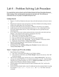
RoboPi is the most advanced robot controller add-on board for the Raspberry Pi available at this time.
RoboPi adds an eight-core 32-bit microcontroller running at 100Mhz to the Raspberry Pi in order to
off-load hard real time I/O and allow more precise timing than Linux running on the Pi allows.
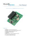
RoboPi stacked on top of a Model A
Raspberry Pi
RoboPi can also be stacked on top of
Model B Raspberry Pi's
RoboPi Features
•
•
•
•
•
•
•
•
•
•
•
•
•
•
Parallax Propeller P8X32 eight core 32 bit Risc microcontroller running at 100Mhz
Each of the eight cores provides up to 25MIPS as most instructions take only 4 clock cycles
three ten-pin Mikronauts I/O module expansion connectors (P0-P7, P8-P15, P16-P23)
24 servo compatible headers on P0..P23
◦ P0-P7 jumper selectable power from Pi's 5VDC supply or external servo power supply
◦ P8-P15 jumper selectable power from Pi's 5VDC supply or external servo power supply
◦ P16-P23 is powered by 5V from the Pi expansion header for sensors
Screw terminal for providing external power for Servo connectors P0-P15
8 servo compatible headers for an eight channel 0-5V analog to digital converter with choice of
◦ MCP3008 for 10 bit A/D conversion
◦ MCP3208 for 12 bit A/D conversion
Choice of 256Kbit or 512Kbit boot EEPROM for the Propeller
On-board voltage regulation providing 3.3V with power on LED from the 5V on the Pi header
4 pin I2C expansion header for the Raspberry Pi
4 pin I2C expansion header for the Propeller
5 pin HCOM connector for use with PropPlug in stand alone operation (optional)
Mikronauts EZasPi prototyping board can stack below RoboPi
Mikronauts Pi Jumper can stack on top of RoboPi
Mikronauts SchoolBoard ][ and other Propeller products are compatible with RoboPi
http://Mikronauts.com
4
2014-01-27
RoboPi v1.00
User Manual v0.85
Copyright 2014 William Henning
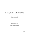
RoboPi Printed Circuit Board
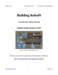
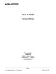
Here is a top view of where parts are located on the RoboPi printed circuit board:
You can refer to this image while wiring your robot after assembling your RoboPi.
PLEASE NOTE
The “PROPPLUG” connection is for stand-alone RoboPi operation (where RoboPi is NOT stacked on
top of a Raspberry Pi. Pins 1-4 are the same as PropPlug (Pin 1 is GND), Pin 5 adds 3.3V for SerPlug.
Plugging in a PropPlug while RoboPi is stacked on the Raspberry Pi may damage your
Raspberry Pi, PropPlug and/or RoboPi.
http://Mikronauts.com
5
2014-01-27
RoboPi v1.00
User Manual v0.85
Copyright 2014 William Henning
RoboPi I/O Pin Definitions
Before you can write programs for your RoboPi based robot, you have to learn what resources are
available for you to connect to sensors, motors and other devices or boards.
P0-P7: SERVO 1 – SERVO 8
•
•
•
10 pin EXP1 connector connected directly to processor pins, 3v3 I/O only
connects to signal pin on SERVO1-8 through a 2k4 current limiting resistor, 5V I/O safe
For the servo header, SV2 selects between the Pi's 5V and VBat from the screw terminal
P8-P15: SERVO 9 – SERVO 16
•
•
•
10 pin EXP2 connector connected directly to processor pins, 3v3 I/O only
connects to signal pin on SERVO9-16 through a 2k4 current limiting resistor, 5V I/O safe
For the servo header, SV3 selects between the Pi's 5V and VBat from the screw terminal
P16-P23: SENSOR 1 – SENSOR 8
•
•
•
10 pin EXP3 connector connected directly to processor pins, 3v3 I/O only
connects to signal pin on SENSOR1-8 through a 2k4 current limiting resistor, 5V I/O safe
the Pi's 5V is used for SENSOR1-8 to provide cleaner power to Ping's etc
P24-P27: SPI port for MCP3008/MCP3208
•
•
•
•
P24 is MISO, connected to DO on ADC through a 2k4 current limiting resistor
P25 is MOSI
P26 is CLK
P27 is /CS
ADC1-ADC8: 0-5V Analog inputs
•
•
connects to the signal pin on ADC1-8 servo style header
the Pi's 5V is used for ADC1-8 to provide cleaner power to Ping's etc
http://Mikronauts.com
6
2014-01-27
RoboPi v1.00
User Manual v0.85
Copyright 2014 William Henning
RoboPi Expansion Connectors
Raspberry Pi I/O header pins
•
RoboPi requires exclusive use of RX/TX
•
RoboPi makes the Raspberry Pi I2C available on a Mikronauts four-pin 3v3 I2C header
•
All other Raspberry Pi I/O pins are available for your use
•
Mikronauts EZasPi was designed to stack between RoboPi and Raspberry Pi for expansion
•
Mikronauts EZasPi (B) was designed to stack below the Raspberry Pi for more expansion
EXP1/EXP2/EXP3 3v3 Expansion Connectors
•
EXP1 is for Propeller pins P0-P7, and servo connectors 1-8
•
EXP2 is for Propeller pins P8-P15, and servo connectors 9-16
•
EXP3 is for Propeller pins P16-P23, and sensor connectors 1-8
•
Mikronauts 3v3 10 pin modules can be used in EXP1/EXP2/EXP3
•
You must not use the 3 pin servo connectors for pins used by a 10 pin module
PI-I2C Header
•
For using 3v3 I2C expansion modules with RoboPi
PROP-I2C Header
•
For using 3v3 I2C expansion modules with the Raspberry Pi
PROPPLUG Header
•
For programming RoboPi when it is not mounted on a Raspberry Pi
•
Intended for stand-alone RoboPi applications
•
DO NOT USE WHEN MOUNTED ON A RASPBERRY PI
http://Mikronauts.com
7
2014-01-27
RoboPi v1.00
User Manual v0.85
Copyright 2014 William Henning
Using RoboPi with the Raspberry Pi
Downloading & Installing Raspbian (Debian for the Pi)
If you already have Raspbian running on your Raspberry Pi, you can skip to Step 4
Installing Raspbian on your Raspberry Pi is required before you can use and control RoboPi with your
Raspberry Pi. The Raspberry Pi Foundation has made this easy, by providing downloadable images of
the Raspbian operating system, with instructions for using PC's, Mac's and Linux computers to make a
bootable Raspbian SD card.
Step 1: Get a compatible Class 10 speed SD card, 8GB – 32GB in size.
You can find a database of SD cards that are known to work with the Raspberry Pi at:
http://elinux.org/RPi_SD_cards
Other SD cards are likely to work as well, I suggest Class 10 for speed.
Step 2: Download the latest Raspbian image
You can find the latest version of Raspbian at:
http://www.raspberrypi.org/downloads/
Step 3: Install Raspbian
The Raspberry Pi foundation provides excellent instructions on how to make a bootable Raspbian SD
card for your Raspberry Pi with your PC/Mac/Linux computer at:
http://www.raspberrypi.org/documentation/installation/installing-images/README.md
http://Mikronauts.com
8
2014-01-27
RoboPi v1.00
User Manual v0.85
Copyright 2014 William Henning
Step 4: Using the Raspberry Pi serial port with RoboPi
The Raspberry Pi has 3.3V serial RX and TX signals available on its 26 pin header.
Normally this port is configured to display boot messages, after which it becomes a serial console.
My favorite small text editor is 'joe', which you can install with
sudo apt-get install joe
then
sudo joe /boot/cmdline.txt
remove “console=ttyAMA0, 115200 kgdboc=ttyAMA0, 115200”
sudo joe /etc/inittab
Find the line
T0:23:respawn:/sbin/getty -L ttyAMA0 115200 vt100
and insert a '#' in front of T0:23
For the changes to take effect, type
sudo shutdown now -r
http://Mikronauts.com
9
2014-01-27
RoboPi v1.00
User Manual v0.85
Copyright 2014 William Henning
Step 5: Installing RoboPiLib
Download the latest version of RoboPiLib.zip from the RoboPi product page at:
http://www.mikronauts.com/raspberry-pi/robopi/
Step 6: Installing the RoboPi Firmware
Download the latest version of RoboPiObj.zip from the RoboPi product page at:
http://www.mikronauts.com/raspberry-pi/robopi/
You will also need to download the latest version of propeller_load.zip from the product page.
Step 7: Installing SimpleIDE for the Raspberry Pi (OPTIONAL)
You only need to install SimpleIde if you want to write your own custom Propeller software for RoboPi
on your Raspberry Pi, and do not wish to use the RoboPi firmware and RoboPiLib.
Only advanced users should attempt to program RoboPi from the “bare metal”
Here is how you can install the Propeller SimpleIDE development environment:
http://Mikronauts.com
10
2014-01-27
RoboPi v1.00
User Manual v0.85
Copyright 2014 William Henning
Introducing RoboPiLib
RoboPiLib is a library designed to interface the Raspberry Pi with the RoboPi firmware.
RoboPiLib was designed to make it easy to write programs on the Raspberry Pi that use all of the
firmware features of RoboPi, and was designed to be familiar to those coming to RoboPi from
WiringPi, Arduino or Wiring environments.
RoboPiLib is available for both Python and C, and the native Spin object uses the same API as
RoboPiLib.
The Python interface that is almost identical to the C interface – all you have to do is prefix the library
function names as follows:
Python Examples:
import RoboPiLib as RoboPi
# connect to RoboPi
RoboPi.RoboPiInit(“/dev/ttyAMA0”,115200)
# set pin 16 to an output and write 1 to it
RoboPi.pinMode(16,RoboPi.OUTPUT)
RoboPi.digitalWrite(16,1)
# set pin 17 to a PWM output and generate a 50% PWM on pin 17
RoboPi.pinMode(17,RoboPi.PWM)
RoboPi.analogWrite(17,127)
# read analog input 0
print RoboPi.analogRead(0)
http://Mikronauts.com
11
2014-01-27
RoboPi v1.00
http://Mikronauts.com
User Manual v0.85
12
Copyright 2014 William Henning
2014-01-27
RoboPi v1.00
User Manual v0.85
Copyright 2014 William Henning
Python RoboLib Constants
Digital pins can be configured for one of the following four modes:
INPUT
pin mode for a digital input
OUTPUT
pin mode for a digital output
PWM
pin mode for a PWM output (0..255)
SERVO
pin mode for a servo output (0..2500)
Python RoboPiLib Functions
RoboPiInit(device, bps)
use RoboPiInit(“/dev/ttyAMA0”,115200)
RoboPiExit()
close the serial connection with RoboPi
readMode(pin)
returns int
pinMode(pin, mode)
digitalRead(pin)
returns INPUT/OUTPUT/SERVO/PWM
set pin to one of INPUT/OUTPUT/SERVO/PWM
returns int
digitalWrite(pin, val)
returns 0 or 1 state of pin
sets pin to 0 or 1
analogRead(chan)
returns int
returns 0..1023 from specified channel
analogReadRaw( pin)
returns int
returns 0..4095 from specified channel
analogWrite(pin, val)
servoRead(pin)
write 0..255 to PWM pin (off to full on)
returns int
servoWrite(pin, val)
readDistance(int pin)
return last servo value written to pin
set servo on pin to val (0..2500 us)
returns int
return distance to nearest object in milimeters
In your program, include the following at the top:
import RoboPiLib as RoboPi
See the example on the previous page to see how to use the Python interface.
http://Mikronauts.com
13
2014-01-27
RoboPi v1.00
User Manual v0.85
Copyright 2014 William Henning
C RoboPiLib Constants
Digital pins can be configured for one of the following four modes:
INPUT
pin mode for a digital input
OUTPUT
pin mode for a digital output
PWM
pin mode for a PWM output (0..255)
SERVO
pin mode for a servo output (0..2500)
C RoboPiLib Functions
void
RoboPiInit(char *device, int bps)
use RoboPiInit(“/dev/ttyAMA0”,115200)
void
RoboPiExit()
close the serial connection with RoboPi
int
readMode(int pin)
returns INPUT/OUTPUT/SERVO/PWM
void
pinMode(int pin, int mode)
set pin to one of INPUT/OUTPUT/SERVO/PWM
int
digitalRead(int pin)
returns 0 or 1 state of pin
void
digitalWrite(int pin, int val)
sets pin to 0 or 1
int
analogRead(int chan)
returns 0..1023 from specified channel
int
analogReadRaw(int pin)
returns 0..4095 from specified channel
void
analogWrite(int pin, int val)
write 0..255 to PWM pin (off to full on)
int
servoRead(int pin)
return last servo value written to pin
void
servoWrite(int pin, int val)
set servo on pin to val (0..2500 us)
int
readDistance(int pin)
return distance to nearest object in milimeters
getPacket/putPacket for advanced users only - requires modifying RoboPi firmare
int
putPacket(char c, char *bf, int ln)
send a custom packet to RoboPi
int
getPacket(char *c, char *bf, int *ln) receive response to custom packet sent to RoboPi
In your program, include “RoboPiLib.h”, and add RoboPiLib.o to your command line as follows:
gcc -o myprog myprog.c RoboPiLib.o
http://Mikronauts.com
14
2014-01-27
RoboPi v1.00
User Manual v0.85
Copyright 2014 William Henning
Using RoboPi without a Raspberry Pi (stand alone operation)
Installing SimpleIDE on PC/Mac/Linux for stand-alone RoboPi use
Parallax has written an excellent guide for installing SimpleIDE at:
http://learn.parallax.com/propeller-c-set-simpleide
Introducing RoboPiObj
If you want to run RoboPi stand-alone (without a Raspberry Pi) you can still take advantage of the
RoboPI API natively.
RoboPiObj.spin is the top-level Spin object for implementing the functionality that is exposed by the
firmware; and as such, it can be used directly from Spin programs running on RoboPi's Propeller
micrcocontroller.
Please note – this is only recommended for those that want to get to the “bare metal”, as it means that
your robot will be controlled by RoboPi's propeller – and not by a Raspberry Pi or external computer.
You can ofcourse implement your own protocol, and even ignore RoboPiObj, by writing from the
ground up – but I think you will find that RoboPiObj takes care of the low level details for you, and lets
you concentrate on your application.
http://Mikronauts.com
15
2014-01-27
RoboPi v1.00
User Manual v0.85
Copyright 2014 William Henning
RoboPiObj Constants
INPUT
pin mode for a digital input
OUTPUT
pin mode for a digital output
PWM
pin mode for a PWM output (0..255)
SERVO
pin mode for a servo output (0..2500)
RoboPiObj Methods
start
Initialize RoboPiObj, start service cogs
pinMode(pin, mode)
set digital pin to specified mode
readMode(pin)
read current mode of digital pin
digitalRead(pin)
read current value (0 or 1) at pin, regardless of mode
digitalWrite(pin)
write 0 or 1 to digital pin
analogRead(chan)
read analog input channel, scale to 0..1023 return value
analogReadRaw(chan)
read analog input channel, return raw 0..4095 value
analogWrite (pin, value)
write PWM value to pin, 0 is off, 255 is fully on
servoWrite(pin, value)
write servo position to pin , 0 to 2500 microseconds
servoRead(pin, value)
return last servo position written to pin
readDistance(int pin)
return distance to nearest object in milimeters
delay(ms)
delay for ms milliseconds
delayMicroseconds(us)
delay for us microseconds
RoboPiObj Resource Utilization
RoboPiObj currently uses 4944 bytes of EEPROM/RAM and two cogs for drivers,
ADC_INPUT_DRIVER
MCP3208 driver object
PWM_32_v4
PWM/Servo driver object
http://Mikronauts.com
16
2014-01-27
RoboPi v1.00
User Manual v0.85
Copyright 2014 William Henning
How to use Digital Inputs
Reading Bumper Switches
Probably the simplest digital input possible is a switch.
<insert schematic of two bumper switches, 100k pullup to 5v, shorts to ground when closed>
#include <stdio.h>
#include “RoboPiLib.h”
#define LEFT_BUMPER 22
#define RIGHT_BUMPER 23
#define PRESSED 0
int main(int argc, char *argv[]) {
RoboPiInit(“/dev/ttyAMA0”,115200);
pinMode(LEFT_BUMPER, INPUT);
pinMode(RIGHT_BUMPER, INPUT);
while (1) {
if (digitalRead(LEFT_BUMPER)==PRESSED)
puts(“Left Bumper Pressed”);
if (digitalRead(RIGHT_BUMPER)==PRESSED)
puts(“Right Bumper Pressed”);
sleep(1); // only check once per second
}
}
http://Mikronauts.com
17
2014-01-27
RoboPi v1.00
User Manual v0.85
Copyright 2014 William Henning
How to use Digital Outputs
The simplest way of demonstrating a digital output is to use it to light an LED.
Using LED's to show which bumper is pressed
<insert schematic of two LED's connected to EXP pins through 470R resistors>
#include <stdio.h>
#include “RoboPiLib.h”
#define LEFT_BUMPER 22
#define RIGHT_BUMPER 23
#define LEFT_LED 8
#define RIGHT_LED 9
#define PRESSED 0
int main(int argc, char *argv[]) {
RoboPiInit(“/dev/ttyAMA0”,115200);
pinMode(LEFT_BUMPER, INPUT);
pinMode(RIGHT_BUMPER, INPUT);
pinMode(LEFT_LED, OUTPUT);
pinMode(RIGHT_LED, OUTPUT);
while (1) {
digitalWrite(LEFT_LED, ~digitalRead(LEFT_BUMPER));
digitalWrite(RIGHT_LED, ~digitalRead(RIGHT_BUMPER));
}
}
http://Mikronauts.com
18
2014-01-27
RoboPi v1.00
User Manual v0.85
Copyright 2014 William Henning
How to use Analog Inputs
Reading a Potentiometer
Probably the simplest analog input possible is a potentiometer.
<insert schematic of potentiometer as voltage divider going to analog input>
#include <stdio.h>
#include “RoboPiLib.h”
#define POT 0
int main(int argc, char *argv[]) {
RoboPiInit(“/dev/ttyAMA0”,115200);
while (1) {
printf(“Potentiometer value is %d\n”, analogRead(POT));
sleep(1); // only check once per second
}
}
Reading a CdS Photocell (light sensor)
<insert schematic of CdS circuit>
Connect a 10K pullup to the signal pin of an analog input to +5V, also connect one side of the CdS to
the signal pin. Connect the other leg of the CdS to GND.
Use analogRead(ch) to read SirMorph sensors, and you will get a value between 0..1023 representing
the amount of light detected by the CdS sensor.
Reading SirMorph (short range distance / line sensor)
SirMorph provides a standard 3-pin Sig/+/GND interface that can be plugged directly into any of the
eight analog inputs on RoboPi.
Use analogRead(ch) to read SirMorph sensors, and you will get a value between 0..1023 representing
the amount of light reflected into the photo transistor.
http://Mikronauts.com
19
2014-01-27
RoboPi v1.00
User Manual v0.85
Copyright 2014 William Henning
How to use Servos
#include <stdio.h>
#include "RoboPiLib.h"
#define LEFT_SERVO
#define RIGHT_SERVO
0
1
#define SERVO_MIN
#define SERVO_MAX
#define SERVO_REV
500
2500
(SERVO_MIN+SERVO_MAX)
int main(int argc, char *argv[]) {
int i;
RoboPiInit("/dev/ttyAMA0",115200);
pinMode(LEFT_SERVO, SERVO);
pinMode(RIGHT_SERVO, SERVO);
while (1) {
for(i=SERVO_MIN;i<=SERVO_MAX;i+=100) {
servoWrite(LEFT_SERVO, i);
servoWrite(RIGHT_SERVO, SERVO_REV-i);
printf("LEFT SERVO = %d\n", servoRead(LEFT_SERVO));
printf("RIGHT SERVO = %d\n", servoRead(RIGHT_SERVO));
sleep(1);
}
}
}
Controlling a Continuous Rotation Servo
If you are using continous rotation servos, the above code will cause the two servos run in one
direction, then the opposite direction, at varying speed.
Controlling a Standard Servo
If you are using standard servos, the above code will turn the servos as far as possible in one direction,
then the other direction.
http://Mikronauts.com
20
2014-01-27
RoboPi v1.00
User Manual v0.85
Copyright 2014 William Henning
How to use PWM to control Gear Motors
Standard motor drivers normally are controlled by two or three digital signals per motor.
EN/A/B Three Wire Driver
The popular L293D and L298 motor drivers are often configured for EN/A/B three wire control.
For three wire drivers, use digitalWrite() to set the two direction pins, then use analogWrite() to
control the motor speed using pulse width modulation. Please note that the minimum speed will be
different for different motors.
Some driver boards permanently tie EN high in order to use only two pins, however I do not
recommend this practice as it is harder on both the motors and batteries (more later).
EN
0
1
Function
Disable the motor driver, motor coasts
Enable the motor, motor turns in direction specified by A or B
Note:
Some motors have an active low input, in which case 0 enables the motor, and 1 coasts.
Check the data sheet for your motor controller (or motor controller chip) for details.
AB
0 0
0 1
1 0
1 1
Function
Break
Rotate in one direction
Rotate in opposite direction
Break
http://Mikronauts.com
21
2014-01-27
RoboPi v1.00
User Manual v0.85
Copyright 2014 William Henning
A/B Two Wire interface
For two wire drivers, use digitalWrite() to set the direction you are NOT going in to 0, then use
analogWrite() to control the motor speed using pulse width modulation for the direction you want the
motor to turn. Please note that the minimum speed will likely be higher for two wire motors, and
different for different motors.
The inexpensive low current L9110S h-bridge is one example of a two wire A/B interface, however
many L293D and L298 boards tie EN high to effectively become two pin drivers.
AB
0 0
0 1
1 0
1 1
Function
Break
Rotate in one direction
Rotate in opposite direction
Break
EN/DIR/PWM Three Wire Driver
Some motor drivers will have an EN signal, but use extra logic to to use one pin as motor direction, and
another as a PWM input to control the motor speed.
For these drivers, use digitalWrite() to set the enable and direction pins, then use analogWrite() to
control the motor speed using pulse width modulation. Please note that the minimum speed will be
different for different motors.
DIR/PWM Two Wire Driver
Other motor drivers use extra logic to to use one pin as motor direction, and another as a PWM input to
control the motor speed.
For these drivers, use digitalWrite() to set direction pin, then use analogWrite() to control the motor
speed using pulse width modulation. Please note that the minimum speed will be different for different
motors.
http://Mikronauts.com
22
2014-01-27
RoboPi v1.00
User Manual v0.85
Copyright 2014 William Henning
Why the ENABLE signal of three wire drivers is useful
Most motor drivers will actively break the motor if the A and B inputs are at the same level.
When PWM speed control is used, both inputs are guaranteed to be driven low during the “off” period
of the PWM signal – which will short the two motor leads, actively breaking.
This is less than ideal for the motor, as it will get short spurts of power, then break, repeatedly.
The practical effect of this is that low speed motor control will not be linear, and the motor will sound
like it is grinding.
http://Mikronauts.com
23
2014-01-27
RoboPi v1.00
User Manual v0.85
Copyright 2014 William Henning
Two pin motor driver sample code
#include <stdio.h>
#include "RoboPiLib.h"
#define MOTORA_IA
12
#define MOTORA_IB
13
#define MOTORB_IA
14
#define MOTORB_IB
15
int main(int argc, char *argv[]) {
int i;
RoboPiInit("/dev/ttyAMA0",115200);
while(1) {
// set both motors FORWARD
pinMode(MOTORA_IA,PWM);
pinMode(MOTORA_IB,OUTPUT);
digitalWrite(MOTORA_IB,0);
pinMode(MOTORB_IA,PWM);
pinMode(MOTORB_IB,OUTPUT);
digitalWrite(MOTORB_IB,0);
for(i=0;i<256;i+=16) {
analogWrite(MOTORA_IA, i);
analogWrite(MOTORB_IA, i);
sleep(1);
}
http://Mikronauts.com
24
2014-01-27
RoboPi v1.00
User Manual v0.85
Copyright 2014 William Henning
for(i=255;i>0;i-=16) {
analogWrite(MOTORA_IA, i);
analogWrite(MOTORB_IA, i);
sleep(1);
}
// set both motors REVERSE
pinMode(MOTORA_IA,OUTPUT);
digitalWrite(MOTORA_IA,0);
pinMode(MOTORA_IB,PWM);
pinMode(MOTORB_IA,OUTPUT);
digitalWrite(MOTORB_IA,0);
pinMode(MOTORB_IB,PWM);
for(i=0;i<256;i+=16) {
analogWrite(MOTORA_IB, i);
analogWrite(MOTORB_IB, i);
sleep(1);
}
for(i=255;i>0;i-=16) {
analogWrite(MOTORA_IB, i);
analogWrite(MOTORB_IB, i);
sleep(1);
}
}
}
http://Mikronauts.com
25
2014-01-27
RoboPi v1.00
User Manual v0.85
Copyright 2014 William Henning
How to Read Analog Distance Sensors
The Sharp GP2Y0A02YK0F is an excellent infrared distance sensor that uses a 5V supply and
typically draws only 33mA and can present a new reading every 50ms.
You can find the data sheet at:
http://www.sharpsma.com/webfm_send/1487
It has a very useful range of 20cm to 150cm, and is extremely easy to use. There are other sensors in
the same family covering 10cm-80cm, and even 100cm-500cm – but neither are as useful as the 20cm150cm GP2Y0A02YK0F.
Please note that the analog output of the sensor is unreliable at ranges shorter than 15cm
Unfortunately the output voltage is not linear with respect to the distance to the object, however it is
easy to construct a table of voltages corresponding to the distance to object in 10cm increments.
Finer distance measurement can be approximated by using linear interpolation as the line segments
between the 10cm data points can be reasonably approximated by straigt line segments.
Dist = analogRead(IR_Channel)
As analogRead returns 0 for 0V and 1023 for 5V, we can scale its output to 1/100th of a volt by
Dist = (500 * Dist)/1024
Giving us Dist as 0 for 0V, and 500 for 5V
Of course, you could do the reading & scaling in one step:
Dist = (500 * analogRead(IR_Channel))/1024
Please see page 5 of the data sheet for the graph of voltage vs. distance.
http://Mikronauts.com
26
2014-01-27
RoboPi v1.00
User Manual v0.85
Copyright 2014 William Henning
How to Read Digital Ultrasonic Range Sensors
The RoboPi firmware implements preliminary support ultrasonic range sensors.
All supported ultrasonic distance sensors will use a generic interface
RoboPiLib:
int
readDistance(int ch)
RoboPiObj:
readDistance(ch) will return the distance to the nearest object in millimeters.
Supported Ultrasonic Sensors:
HC-SR04
PARALLAX_PING
SEEDSTUDIO_136B
tested, working
not tested, should function
not tested
How to connect your ultrasonic range sensor:
HC-SR04 pin
RoboPi Pin
Vcc
Trig
Echo
GND
Servo header red wire (any of 24 servo three pin headers)
10 pin female header corresponding to selected pin
Servo header white wire
Servo header black wire
Ping pin
RoboPi Pin
5V
SIG
GND
Servo header red wire
Servo header white wire
Servo header black wire
Seeedstudio 136B pin
RoboPi Pin
5V
SIG
GND
Servo header red wire
Servo header white wire
Servo header black wire
http://Mikronauts.com
(use any of 24 servo three pin headers)
(use any of 24 servo three pin headers)
(use any of 24 servo three pin headers)
27
2014-01-27
RoboPi v1.00
User Manual v0.85
Copyright 2014 William Henning
Stand-Alone Operation Requirements
Supply 5V to RoboPi via one of:
•
pins 2 & 4 of the 2x13 pin Pi Header
•
“Pi5V” terminal of power selection header SV2 or SV3
Supply GND to RoboPi via one of:
•
pins 9 & 14 of the Pi Header
•
GND terminal of the external motor power screw terminal
If you will never mount your RoboPi on a Raspbery Pi, you could mount a two pin screw terminal on
pins 2 (5V) & 6 (GND) for supplying 5V.
Use a PropPlug to program your stand-alone RoboPi.
http://Mikronauts.com
28
2014-01-27
RoboPi v1.00
User Manual v0.85
Copyright 2014 William Henning
Appendix A: Software
•
•
•
•
•
Raspbian Wheezy or later
SimpleIDE 0.8.4 or later
propeller-load3 or later
RoboPi API v1.0 or later
RoboPiLib v1.0 or later
Appendix B: Data Sheets
http://www.parallax.com/sites/default/files/downloads/P8X32A-Propeller-Datasheet-v1.4.0_0.pdf
http://www.parallax.com/sites/default/files/downloads/P8X32A-Web-PropellerManual-v1.2.pdf
http://ww1.microchip.com/downloads/en/DeviceDoc/21298c.pdf
http://ww1.microchip.com/downloads/en/DeviceDoc/21754M.pdf
You can find the data sheets for the listed Digikey part numbers at Digikey.com by typing in the part
number and clicking on the pdf icon on the resulting page.
Appendix C: Support
For Raspberry Pi support, including Raspbian, please see the Raspberry Pi forums at:
http://www.raspberrypi.org/forum/
For Parallax Propeller support, see the Parallax forum at:
http://forums.parallax.com/forumdisplay.php/65-Propeller-1-Multicore-Microcontroller
For RoboPi support, please visit the RoboPi thread in the Propeller forum at:
http://forums.parallax.com/showthread.php/153275-Propeller-add-on-for-Raspberry-Pi-RoboPi..-themost-advanced-robot-controller-for-Pi
or the new Mikronauts forums:
http://forums.mikronauts.com
http://Mikronauts.com
29
2014-01-27
RoboPi v1.00
User Manual v0.85
Copyright 2014 William Henning
Appendix D: RoboProp Software Compatibility:
•
•
•
use the supplied 6.250Mhz crystal for 100Mhz operation
use 24LC512 EEPROM
use MCP3208
While there is no motor driver on RoboPi, if you connect a two channel motor controller as follows it
will be RoboProp compatible:
•
•
•
•
•
Tie EN1-2 and EN3-4 high
P8 to IN1
P9 to IN2
P10 to IN3
P11 to IN4
If you want to have a uSD card compatible with RoboProp, attach it as follows:
•
•
•
•
P12 to MISO
P13 to MOSI
P14 to CLK
P15 to /CS
http://Mikronauts.com
30
2014-01-27
RoboPi v1.00
User Manual v0.85
Copyright 2014 William Henning
Appendix E: Frequently Asked Questions
Q: Where can we buy RoboPi?
A: Currently you can buy RoboPi:
Directly from us – please email us at [email protected] with desired quantity and postal
address, we will be happy to send you a quote. We accept PayPal from verified buyers.
From our Ebay store – please visit us at out Mikronauts Ebay store!
<add actual URL>
Distributors and dealers are welcome to contact us for quantity discounts – we would love to have you
on-board!
Q: Are quantity and educational discounts available for RoboPi?
A: Yes! We are happy to offer quantity based discounts to our educational users and distributors.
Please contact us for a custom quote.
Q: Can we make our own RoboPi printed circuit boards?
A: I am afraid not. While RoboPi is an open platform in that it is fully documented, with source code
available for its libraries and demo applications, RoboPi is a commercial product, and may not be
copied.
Q: Can we use the less expensive MCP3008 10 bit analog to digical converter instead of the
MCP3208?
A: Yes, you can – but the driver needs to be modified, and the RoboPi libraries and demonstration
programs assume that an MCP3208 is used. We intend to offer a merged MCP3208/MCP3008 driver
soon which will allow a common code base.
Q: Do you have any distributors in <name of country>?
A: We are working hard to set up our distribution network. Please email your favorite web stores and
have them contact us if they are interested in RoboPi.
http://Mikronauts.com
31
2014-01-27