1
Development of an Autonomous Wheelchair
By
Matthew Robinson
Bachelor of Engineering (Electronics)
Supervisor:
Dr. Nasser Asgari
Submitted November 2014
Submitted to the School of Computer Science, Engineering and Mathematics in
the Faculty of Science and Engineering in partial fulfilment of the requirements
for the degree of Bachelor of Engineering (Electronics) at Flinders University –
Adelaide Australia.
I certify that this work does not incorporate without acknowledgement any material previously
submitted for a degree or diploma in any university; and that to the best of my knowledge and
belief it does not contain any material previously published or written by another person except
where due reference is made in the text.
Signed:
______________________________________________
Date:
__________________________________________
Table of Contents
Table of Contents ................................................................................................ 1
i. Acknowledgements ......................................................................................... 3
ii. List of Figures................................................................................................. 4
iii. Abstract ......................................................................................................... 6
1
2
3
Introduction............................................................................................... 7
1.1
System Overview ............................................................................................ 7
1.2
Related Work ................................................................................................. 8
Top Level Control ................................................................................... 10
2.1
MATLAB Top Level Control ..................................................................... 11
2.2
dsPIC Top Level Control ............................................................................ 12
2.3
MATLAB to dsPIC Communication ......................................................... 15
Electronics Design................................................................................... 16
3.1
Controlling the Motors ................................................................................ 16
3.1.1 Controlling the Movements through Software................................... 17
3.2
Manual Control Override ........................................................................... 18
3.3
SPI Communication..................................................................................... 20
3.3.1 Digital Potentiometer Communication .............................................. 20
3.3.2 ADC Communication ........................................................................ 23
4
Visual Sensors ......................................................................................... 25
4.1
Base Mounted Infrared Sensors ................................................................. 25
4.2
Servo Motor with Sonar and IR ................................................................. 26
4.3
Kinect Sensor................................................................................................ 27
1
5
Navigation ................................................................................................ 28
5.1
Wall Tracking .............................................................................................. 28
5.1.1 Maintaining Wall Proximity .............................................................. 28
5.1.2 Obstacle Avoidance ........................................................................... 31
6
5.2
Roaming ........................................................................................................ 32
5.3
Moving Through Doorways ........................................................................ 32
Limitations and Future Development ................................................... 35
6.1
Lack of Movement Precision....................................................................... 35
6.1.1 Incremental Encoders for Tracking Movements ................................ 35
6.1.2 Direct Motor Control ......................................................................... 35
6.2
Issues When Moving Through Doorways .................................................. 36
6.2.1 Improved Door Finding ..................................................................... 36
6.3
Collision Detection ....................................................................................... 37
6.4
Mapping ........................................................................................................ 38
6.5
IMU Sensor for Incline Detection............................................................... 38
6.6
Top Level Control - Robotics Operating System (ROS) .......................... 38
7
Conclusion ............................................................................................... 40
8
References ................................................................................................ 41
9
Glossary ................................................................................................... 42
10
Appendices............................................................................................... 43
10.1
Datasheets ..................................................................................................... 43
10.2
Code .............................................................................................................. 43
10.3
Other ............................................................................................................. 43
2
i. Acknowledgements
Amanullah Karimi, for his project work on the Kinect sensor and door detecting methods.
Shobeir Asayesh, for his work on developing the wheelchair in 2013 which my project would not
have been possible without.
All staff from the engineering workshop for their continued technical assistance and advice.
My supervisor, Dr. Nasser Asgari for his ongoing support from start to finish.
3
ii. List of Figures
Figure 1 - Diagram of the Wheelchair and its Main Components .......................................................... 8
Figure 2 - System Control and Data Flow from a top level perspective ............................................... 10
Figure 3 - Control Flow with User Inputs ............................................................................................. 11
Figure 4 - Callback Function for Stop Button....................................................................................... 12
Figure 5 - dsPIC Top Level Control ..................................................................................................... 13
Figure 6 - PIC Algorithm Execution Selection ..................................................................................... 14
Figure 7 - MATLAB Function for Communicating with dsPIC........................................................... 15
Figure 8 - Default Motor Control from Joystick ................................................................................... 16
Figure 9 - dsPIC to Motor Controller Communication ......................................................................... 17
Figure 10 - Direction Data Type ........................................................................................................... 17
Figure 11 - Speed Calculations ............................................................................................................. 17
Figure 12 - Joystick and ADC Connection ........................................................................................... 18
Figure 13 - Joystick Override Sate Diagram......................................................................................... 19
Figure 14 - SPI Communication Diagram depicting the in/out of the D-POT and ADC ..................... 20
Figure 15 - Digital Potentiometer Communication Specifications ....................................................... 21
Figure 16 - Digital Potentiometer Communication Subroutine ............................................................ 22
Figure 17 - ADC Serial Communication Specifications ....................................................................... 23
Figure 18 - ADC SPI Communication Subroutine ............................................................................... 24
Figure 19 - Infrared Sensor Directional Configuration ......................................................................... 25
Figure 20 - Servo Motor with IR and Sonar ......................................................................................... 26
Figure 21 - IR Sensors for Wall Tracking............................................................................................. 29
Figure 22 - Wall Proximity Algorithm ................................................................................................. 30
Figure 23 - Obstacle Avoidance for Walltracking ................................................................................ 31
Figure 24 - Door Finding Algorithm Visual Representation ................................................................ 33
Figure 25 - Movement Path for Navigating Doorways ......................................................................... 33
Figure 26 - Improved Kinect Readings for Door Detection ................................................................. 36
4
Figure 27 - Contact Bumper Placement for collision detection ............................................................ 37
Figure 28 - Visual Representation of Possible ROS Implementation for Current System ................... 39
5
iii. Abstract
Many physical disabilities hinder a person’s ability to maintain direct control of a wheelchairs
movement. The design of an autonomous wheelchair aims to minimise the amount of user input
required to safely and reliably reach a destination. By analysing various visual sensors through a
dsPIC microcontroller to actuate appropriate movements, a reactive obstacle avoidance navigation
system was designed.
The development process consisted of interfacing several devices to control the motors both
autonomously and through a manual override. Navigational algorithms to move the wheelchair whilst
avoiding collisions were used primarily to perform wall tracking and move through doorways. A
Kinect sensor was used to find the location of a door relative to the wheelchairs current position.
MATLAB was used as the top level controlling software. A program was developed to handle user
inputs from a GUI, process Kinect data, and communicate important information to the dsPIC
microcontroller.
The resulting system was not only able to navigate and avoid obstacles, but also make intelligent
destination decisions when locating doorways. The fully functional design will serve as a foundation
for further development including more advanced navigation and an input system derived from the
users brain, eye and/or speech activity.
6
1 Introduction
Some medical conditions render the user of a manually controlled wheelchair unable to operate or
reliably maintain direct control of the movements. This project involved the development of a smart
wheelchair capable of perceiving and navigating its surroundings and autonomously actuating
movements whilst requiring minimal amounts of input from the user.
As well as being able to avoid collisions through reactive obstacle avoidance techniques, it was also
important for the system to be able to make intelligent decisions on a destination. The aim was not
only to demonstrate that this is achievable by producing a fully functional system, but to also provide
the foundation for further development.
Although not yet implemented, it is intended that in future development user inputs will be derived
from the scanning of brain, eye or speech activity. As such, many aspects of the design were tailored
with this in mind.
1.1 System Overview
This project involved building upon a pre-existing system (Electronic Design of Brain Controlled
Wheelchair, 2013) whereby several modifications were made to a commercially available manually
controlled wheelchair including mounting various visual sensors and a dsPIC microprocessor to
control the movements.
7
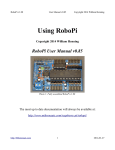
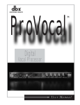
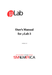
Figure 1 - Diagram of the Wheelchair and its Main Components
A dsPIC micro controller is used to analyse data from the IR and sonar sensors and actuate
appropriate movements to avoid obstacles. An Xbox 360 Kinect sensor is utilised to make high level
destination decisions, namely door locations. The joystick was implemented to provide a manual
control override. A MATLAB program running from a laptop drives the system from a higher level,
handling user input and relaying relevant Kinect data to the dsPIC.
1.2 Related Work
An autonomous wheelchair is not a new concept and has been researched and implemented in several
designs in the past. One example (Preliminary Investigation of a Semi-Autonomous Robotic
Wheelchair Directed Through Electrodes, 1997) has many similarities in the design and objectives of
this project. In their design high level commands are derived from user eye movements, and several
visual sensors are utilised in low level navigation to ensure the chair does not run into any obstacles.
An important aspect of this design is that the wheelchair reacts appropriately to obstacles. By default
the system will execute the commands given by the user, but will take control of the movements when
necessary to avoid collisions. This design idea is important to keep in mind as one objective for this
project is to provide the foundation for a system to be controlled from similar sources.
Our system differs in the fact that as well as being able to reactively avoid obstacles, the wheelchair is
able to make intelligent destination decisions from analysing the Kinect sensor.
8
For detecting points of interest such as obstacles, doorways and clear paths the Kinect sensor is a
device capable of performing these tasks and more. There have been many prior research papers and
systems designed whereby the Kinect sensor is used as a visual sensory input to autonomous robots.
One such work (Mobile Robots Navigation in Indoor Environments Using Kinect Sensor, 2012)
utilises the Kinect sensor to develop a reactive anti-collision system for a ground based autonomous
robot. This system uses a depth map of the environment to determine the location of obstacles. The
field of vision is broken into 6 vertical segments, each defined as either clear or blocked if an object is
detected within a certain distance threshold. Appropriate movements are actuated depending on which
segments are clear or blocked.
The interesting point of this process is that the Kinect depth map has been translated into a model that
the navigational decision making algorithms can easily interpret. This same idea can be applied to the
wheelchair. When locating points of interest, such as obstacles or doorways, the navigation system
need only know the general location relative to the wheelchair. The potential outcome of this is
simple, generic and ultimately more robust navigation algorithms for the dsPIC microcontroller.
9
2 Top Level Control
From the top level the system is driven through MATLAB and the Instrument Control toolbox.
MATLAB was chosen for this task as it is able to communicate with the PIC, allows for user inputs
through a GUI and can perform complex processing on the Kinect depth map.
Figure 2 - System Control and Data Flow from a top level perspective
MATLAB
dsPIC Microcontroller
Handle user inputs from GUI
Read visual sensors
Process Kinect data to find doors
Navigation algorithms
Send door location to PIC
Read joystick inputs
Set PIC operating mode
Actuate Movements
Table 1 - Tasks for MATLAB and PIC
As one of the main goals of this project was to minimise user input, the GUI controlling the system
consists of 5 pushbuttons which set the systems mode of operation.
10
Stop
Mode
Functionality
Wheelchair remains idle, can be controlled manually
Wall-track Left/Right
Maintain proximity to wall, avoid obstacles
Move Through Door
Locate doorway and attempt to navigate through
Roam
Move forward by default, navigate around obstacles
Table 2 - Modes of Operation
When designing the modes of operation, the intention is that in future development the system itself,
not the user, will decide which mode to activate depending on its current situation and objective.
2.1 MATLAB Top Level Control
When the user presses a button to select the operating mode, MATLAB sends a command to the
dsPIC, which will execute the appropriate algorithms associated with the current operating mode.
Figure 3 - Control Flow with User Inputs
The microcontroller will continue to execute according to the last command received until it is
updated, and is initially set to stop mode.
The main control script for MATLAB firstly initialises the serial connection to the microcontroller
and sets up the GUI window. The rest of the programs execution is within call-back functions
associated with each button. That is, after initialisation MATLAB will remain idle until a button is
pressed and will execute segments of code corresponding to that button.
11
function stop_Callback(hstop,eventData)
%Stop button callback function
% change PIC operation to stop mode
if input == 0
disp('Already in stop mode...')
else
input=0;
% change PIC operating mode
PIC_REPLY = send_command(PIC,input)
disp('Manual Mode, autonomous movements stopped')
end
end
Figure 4 - Callback Function for Stop Button
The above is the call-back function associated with the stop button, and the other button functions
follow the same generic form. The outcomes of user button presses are displayed in the terminal in
text to ensure the user is aware of what the wheelchair is doing.
In the software, each operating mode is defined by a 1 byte value which is interpreted the same in
both the PIC and MATLAB programs. In the above case, STOP mode is represented by the number 0.
Firstly, the function checks if it is already in that mode as there is no need to update the PIC if the
condition is true. If it is a new input, then it is forwarded directly to the micro controller so that it can
accordingly change its operating mode. A reply is also received to confirm that the PIC has changed
its mode of operation.
2.2 dsPIC Top Level Control
The microcontroller executes algorithms corresponding to the last mode of operation command
received from MATLAB. The script below is used to implement the upper level of control on the
dsPIC.
12
Figure 5 - dsPIC Top Level Control
In this algorithm the input buffer for UART2 is checked for a command from MATLAB. The
function operating_mode examines the current input and executes the corresponding routines.
13
Figure 6 - PIC Algorithm Execution Selection
The process is quite simple, using a case statement of the input the appropriate algorithm is executed.
A message is sent to MATLAB so that the operator is aware of the current operation of the
wheelchair.
The input may change when the system is attempting to locate doorways and thus an input variable
needs to be returned from the function. This reason for this is that both door locations and operating
modes are sent from MATLAB to the dsPIC via the same communication channel, and the door
finding functions continue to execute until a doorway has been found.
All PIC functions (excluding finding doors) are designed so that they perform only a small step in
each call, i.e., the navigation functions execute and exit quickly, and must be called continuously to
achieve results and movement. Generally, every function call will actuate the motors for
approximately 600ms. This design decision was implemented for several important reasons.
14
Firstly, the MATLAB command is checked more frequently, making the system more responsive to
the GUI button presses.
Secondly, when the user has moved the wheelchair using the joystick and the PIC exits from manual
control, the previous sensor data is invalid for the new position of the wheelchair.
2.3 MATLAB to dsPIC Communication
MATLAB communicates with the dsPIC microprocessor through the UART2 port via USB Virtual
Serial connection. This communication channel is configured to use 8N1 protocol with 115200 baud
rate and carriage return (ASCII 0x0D) terminator. The following MATLAB function was written to
communicate with the PIC.
function reply = send_command( PIC,command )
%send command to PIC
% operating mode, or door location when requested
fopen(PIC);% open the serial object
fwrite(PIC,command);% send the command
reply = fscanf(PIC);% read the reply
fclose(PIC);% close the serial object
end
Figure 7 - MATLAB Function for Communicating with dsPIC
When the command is sent, a reply is also received from the PIC. The reply is displayed in the
MATLAB terminal so that the user can verify that the PIC has received the command and reacted
accordingly. Only 1 byte of data is sent to the PIC however MATLABs input buffer is set to 1024
bytes, allowing for meaningful strings to be received from the PIC and displayed to the user.
15
3 Electronics Design
This section describes in detail the electronic modifications made to the wheelchair in order to control
the motors through both a microcontroller and a manual joystick override. A digital potentiometer was
used to actuate the wheelchairs motors and an ADC chip to read a joystick for manual override.
At the commencement of this project, the devices discussed were already physically installed
including most of the wiring. All other aspects such as interfacing with the microcontroller and all
software developed are solely my own work, except where explicit mention is given.
3.1 Controlling the Motors
The built in motor control board for the wheelchair receives two voltage signals from 0-5 V as input.
One signal tells the wheelchair to turn left or right and the other drives the wheelchair forwards or
backwards. Initially these signals would come directly from the wheelchairs joystick.
Figure 8 - Default Motor Control from Joystick
When idle, the motor control board must receive 2.5V. Applying voltages above or below the idle
voltage will cause the motor control board to actuate the corresponding movements. In order to
control the motors from the dsPIC a multi-channel digital potentiometer was connected to the motor
control board to mimic the joystick signals.
16
Figure 9 - dsPIC to Motor Controller Communication
The micro controller communicates to the digital potentiometer using the Serial Peripheral Interface
(SPI) module. Through this setup, the dsPIC can control the speed and actuation time of the
movements.
3.1.1 Controlling the Movements through Software
From the setup described above, various algorithms were developed to move the wheelchair from
different types of input. One function specifies the desired direction, speed and drive time. For the
direction input an enumerated type was created with 8 different directions.
Figure 10 - Direction Data Type
The function would perform a switch statement on the direction and actuate the appropriate
commands to move the wheelchair in that direction.
The speed input is a byte ranging from 0 – 100 decimal which corresponds to a percentage of the
maximum speed. As seen in the figure the maximum speed for one direction requires a 5V input and
0V for the other direction. Thus a 1-byte speed value for each direction is calculated from the speed
percentage input.
Figure 11 - Speed Calculations
The drive time input is a 16-bit word which corresponds to the motor actuation time in milliseconds.
Once the motors have been appropriately actuated in terms of direction and speed the program is
paused for this specified duration. The movements are then stopped and the function exits.
17
In implementations, the drive time is ideally kept below one second. This is because the program has
to pause whilst the wheelchair is moving, thus no updates on sensor data can be retrieved and
examined.
Various similar algorithms for moving the wheelchair were developed with different combinations.
One such function moves the wheelchair indefinitely in the chosen direction. The reason for this
design was in anticipation of brain/speech control.
3.2 Manual Control Override
The wheelchairs joystick was implemented as a manual control override for the system and was
designed so that manual inputs always have precedence over the autonomous movements. The main
reason for this is to help prevent any harm to either the operator or the wheelchair itself in cases of
unexpected errors. This implementation also serves as a useful tool for positioning the wheelchair
when developing and testing various aspects of the navigation.
As the default direct connection of the joystick to the motor control board was replaced by the digital
potentiometer, the joystick outputs were fed to the dsPIC through a multi-channel analogue to digital
converter (ADC). The ADC communicates with the micro controller through the same SPI channel as
the digital potentiometer, but with some variation in the protocol.
Figure 12 - Joystick and ADC Connection
Effectively, the dsPIC reads the joystick activity through the ADC and forwards the appropriate
commands to the motor control board. The override is implemented by reading the joystick
periodically on a timer interrupt.
18
Figure 13 - Joystick Override Sate Diagram
Every 300ms the program will interrupt and check the output from the ADC chip. If there is any
activity the corresponding voltage signals will be applied to the motor controller. This continues until
no joystick inputs are detected and the main program will then resume execution.
When reading the joystick through the ADC the value returned is a 10-bit word ranging from 100 to
400 decimal which corresponds to the 0 to 5V output respectively. To apply this to the digital
potentiometer the value is scaled to an 8-bit value ranging from 0 to 255.
𝑃𝑂𝑇𝑣𝑎𝑙𝑢𝑒 = (𝐴𝐷𝐶𝑣𝑎𝑙𝑢𝑒 − 100) × 0.85
The result POTvalue is applied to the appropriate channel of the digital potentiometer, thus the
joystick command is successfully forwarded to the motor controller.
19
3.3 SPI Communication
The same SPI module is used to communicate with both the ADC and digital potentiometer. To
effectively communicate with both devices the module was configure to operate in 16-bit mode with
an 89kHz clock in idle high mode. Both devices receive their commands from the same output line of
the PIC, thus the chip select pins are used to enable each device when they are needed.
Figure 14 - SPI Communication Diagram depicting the in/out of the D-POT and ADC
3.3.1 Digital Potentiometer Communication
The digital potentiometer receives a 16-bit message as the input.
20
Figure 15 - Digital Potentiometer Communication Specifications
The high byte (Command Byte) contains a command which tells the device which channels to
activate. The lower byte (Data Byte) determines the output voltage on the selected channels where 0255 corresponds to 0–5V. There is no meaningful reply from this device.
Communication with the digital potentiometer is achieved through the following subroutine.
21
Figure 16 - Digital Potentiometer Communication Subroutine
The two inputs command and data refer to which channels to activate and the voltages applied. The
variable spi_busy is used as a flag to prevent conflict between the two devices so that the PIC will
only communicate with them one at a time.
The two inputs are combined into a 16-bit message. When the transmitting buffer is ready the chip
select bit will be driven low to enable the digital pot. The message is then applied to the buffer and the
chip is disabled when the communications are complete. Although no meaningful reply is received the
receiving buffer is read to clear it.
22
3.3.2 ADC Communication
Communication with the joystick analogue to digital converter involves both sending and receiving.
Figure 17 - ADC Serial Communication Specifications
A 16-bit message is sent as the input. Only the 5 most significant bits are meaningful, which selects
the channel to be converted and the rest of the message contains zeros. The value received by the PIC
contains the voltage conversion in the 10 least significant bits.
23
Figure 18 - ADC SPI Communication Subroutine
The above routine is similar to that of digital potentiometer however a reply is returned. The voltage
conversion is contained within 10 bits and thus a mask is applied.
24
4 Visual Sensors
The various sensors in the system are utilised in the navigation algorithms of the wheelchair to avoid
obstacles, perform wall tracking and find the location of doors. The wheelchair has 5 IR sensors
attached at the base, an IR and sonar sensor mounted to a servo motor at the front and a Kinect sensor
for locating doorways.
The infrared and sonar sensors as well as the servo motor were already installed on the system. Also
implemented was the interfacing of these devices to the microcontroller as well as some low level
software for obtaining the readings. Explicit mention is given to the aspects that were not solely my
own work.
4.1 Base Mounted Infrared Sensors
5 infrared sensors are mounted at the base of the wheelchair. Their main purpose is to detect
proximity when wall tracking and detect obstructions when navigating. The existing sensors were
rearranged to the configuration below.
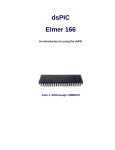
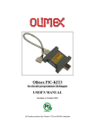
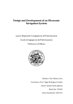
Figure 19 - Infrared Sensor Directional Configuration
The 45 degree angle for the side sensors was chosen as it is an optimum configuration for both wall
following and obstacle detection. When wall following, this configuration allows the wheelchair to
detect corners before they are reached.
The vision of the front sensors will not be obstructed by the legs of the wheelchairs occupant when
placed at this angle.
25
The rear sensor is important as it is the only source of vision behind the wheelchair and is useful to
avoid collisions when reversing.
Each sensor is connected to one of the micro controllers A2D ports. A Dynamic Memory Access
(DMA) service was previously developed to retrieve the data into a buffer and apply the appropriate
distance conversions.
4.2 Servo Motor with Sonar and IR
At the front of the wheelchair a sonar and infrared sensor were attached to a servo motor. This
configuration allows range readings in a 180° degree field of vision in front of the wheelchair. The
servo motor is controlled by a PWM signal from the Output Compare Module of the dsPIC.
Figure 20 - Servo Motor with IR and Sonar
The sonar sensor is useful in detecting obstacles which may be missed by the infrared sensors due to
its relatively wide field of vision. The serial output of the sonar sensor is connected peripheral pin of
the PIC. To read the incoming serial data a “bit-bang” routine uses change notification interrupts to
detect the signal and a timer interrupt to latch each bit of the message. This routine was already
mostly developed but not fully functional. Several aspects were changed and modifications made in
the software to properly interface the sonar sensor with the dsPIC.
The purpose of this is to compensate for the limitations in the Kinect sensors field of view and
processing time. For detecting obstacles and finding clear pathways before making movement
decisions, the sensor readings are sufficient without having to process the Kinect data, which has a
minimum range of 80cm.
A subroutine was developed to obtain range readings at 3 points in front of the wheelchair: front left,
front and front right. These points were 60° from the front view. Similar functions were also
developed to get the readings at specific locations when a multi-point sweep was not necessary.
26
4.3 Kinect Sensor
The functions and algorithms which compute meaningful results from the Kinect data is the project
work of another student and are not discussed here.
An Xbox360 Kinect sensor was used to obtain range readings at every pixel in 80x60 resolution. The
device is driven through Visual Studio and the data is processed in MATLAB.
Using edge detection algorithms, the Kinect sensor was able to detect the location of doorways
relative to wheelchairs current position. The output of this was used in the navigation algorithm for
moving the wheelchair through a doorway.
27
5 Navigation
By utilising all visual sensors, the wheelchair is able to perceive its surrounding and make appropriate
movement decisions. Wall tracking and free roaming algorithms analyse data from the infra-red and
sonar sensors to find a clear path and the Kinect data is also utilised when attempting to locate and
move through doorways.
The navigation exhibits a reactive anti-collision system whereby the current inputs from the sensors
are used to generate appropriate movement actions.
5.1 Wall Tracking
The wheelchair is able to follow a wall and maintain constant proximity whilst also avoiding any
obstacles that are encountered. Wall tracking is an important part of the system as many buildings
contain hallways and corridors. The algorithm developed allows the wheelchair to navigate through a
hallway or corridor, following a straight parallel path if no obstructions are present.
The wall proximity is achieved by examining the two side facing IR sensors corresponding to the side
the wheelchair is tracking. Obstacle avoidance is achieved through utilisation of the servo mounted
infrared and sonar sensors.
5.1.1 Maintaining Wall Proximity
The functions are designed to have the required wall proximity as an input. This is implemented as the
required proximity can be variable to the situation and the nature of the environment the wheelchair is
navigating through.
28
Figure 21 - IR Sensors for Wall Tracking
As both IR sensors are mounted 45° to the perpendicular the required range readings d that
correspond to the desired wall proximity prox can be determined.
𝑑=
𝑝𝑟𝑜𝑥
𝑝𝑟𝑜𝑥
=
𝑠𝑖𝑛45° 0.7071
As the maximum range for the IR sensors is 1.5m, the maximum allowable wall proximity is
constrained to 1m.
Ultimately, the wall tracking is achieved by moving the wheelchair so that both infrared sensors
return a distance reading d within ±10%. The following segment of code demonstrates how the
system maintains wall proximity on the left hand side.
29
Figure 22 - Wall Proximity Algorithm
The first condition to be checked is whether the front left sensor is too far from the wall. If true, the
orientation of the wheelchair can be determined by examining the rear left sensor reading. If the rear
left sensor reading is less than the required distance then we know the wheelchair is pointing to the
right and must veer left to correct itself.
The same deduction method is used when the front sensor gives a reading less than what is required.
If none of the conditions tested are true, then both sensor readings must be within the desired range
meaning that the wheelchair is parallel to the wall at the correct proximity. Thus, it continues to move
forward.
When implemented, the wheelchair exhibits “snaking” movement patterns when first attempting to
correct its proximity. This pattern reduces and eventually ceases as the wheelchair is positioned closer
to the desired distance and perpendicular orientation.
30
5.1.2 Obstacle Avoidance
The wall tracking functions also contain algorithms for detecting and avoiding obstructions in the path
of the wheelchair. The front facing servo mounted infrared and sonar sensors are utilised for both
detecting an obstruction and determining a clear path around it, if it exists. This method is detailed in
the code segment from right hand side wall tracking, which executes before the wall proximity
segment.
Figure 23 - Obstacle Avoidance for Walltracking
Firstly the forward path is checked for obstructions within 1 metre. If detected, the servo motor will
rotate to the right so that the front sensors can detect whether a clear path is available around the
obstacle. If clear, the wheelchair will veer around the object. By default, the system will not execute
any movements when no clear path can be found.
The return statement is added so that the function will exit before the wall proximity algorithm is
executed.
31
5.2 Roaming
When in roaming mode the wheelchair moves freely and avoids obstacles. The movement is forward
by default and will make other movements accordingly when objects are detected in the wheelchairs
path. The servo mounted IR and sonar sensors are used to detect obstacles and find clear paths.
By default, the wheelchair will continue moving in the forward direction. When an obstacle in the
forward path is detected, the servo motor will move 60° to the right and then the left. The wheelchair
will then turn right or left, whichever path is not obstructed, with turning right having the priority. The
wheelchair will reverse if no clear path is found.
This operating mode was developed with the intention that in future implementations this algorithm
can be utilised to allow the system to perceive and map its surroundings and gain positional
awareness.
Another reason for the design was for future use with brain/speech control, whereby the user selects
the direction (in this case forward) and the wheelchair will move in that direction but also reactively
move to avoid obstacles.
5.3 Moving Through Doorways
The algorithm for locating and navigating through doorways encapsulates all parts of the system. It is
unique in the fact that it uses data from the Kinect sensor to make intelligent decisions on a
destination.
At this stage, the output from the Kinect data analysis function yielded 4 possible outcomes for the
door location: Front-Left, Front, Front-Right, No Door. No information on the wheelchairs distance
or orientation to the doorway is available, thus the algorithm was developed according to the
information available.
32
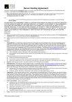
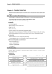
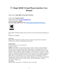
Figure 24 - Door Finding Algorithm Visual Representation
The figure above gives a visual depiction of the algorithm the system uses to locate and move through
a doorway. When this mode is activated, the PIC sends a data request to MATLAB and remains idle
until an update on the door location is returned. Upon receiving this request, MATLAB computes the
Kinect data and sends the door location to the PIC, which then executes a movement sequence to
reposition itself more closely in line with the doorway. The path is first checked for obstacles before
repositioning via the servo mounted IR and sonar sensors.
Figure 25 - Movement Path for Navigating Doorways
33
Depicted is a typical movement sequence for the wheelchair when navigating through doorways. The
system will continue to reposition until the Kinect detects that the door is in front of the wheelchair
and will then attempt to move through it.
The system is unable to detect when the wheelchair has completed the process, thus the mode must be
changed manually. Another limitation is that this process is only viable when the wheelchair begins
with parallel orientation to the doorway, as there is no angular information.
34
6 Limitations and Future Development
As the system is still very much in the prototype stage there are many limitations in the overall
functionality. In this section a critical analysis is given to several key issues. Both the causes and
effects are addressed. Implementation strategies which could solve these issues are discussed in detail
as well other recommendations for further development.
6.1 Lack of Movement Precision
One of the major limitations of this system is the lack of precision in the movements. The motors are
actuated for a given time at a specified speed. Through lengthy trial and error the approximate
combinations to achieve a desired movement can be achieved but are not robust nor reliable and only
very situational.
This limits what the wheelchair can do in terms of navigation. As the Kinect sensor has the potential
to pinpoint destinations for the wheelchair, distance tracking will help enable it to accurately reach
such destinations.
6.1.1 Incremental Encoders for Tracking Movements
The most viable solution for tracking the movements of the wheelchair is to affix incremental
encoders to the wheels. The nature of the dsPIC allows for these devices to be easily implemented in
the system.
The most suitable implementation would be to use the encoder pulses to increment a counter (one of
the timer modules). With a known relationship between distance and pulse counts the system will be
able to track the movements of the wheelchair, which is an important step in positional awareness.
6.1.2 Direct Motor Control
Although the movements can be tracked with encoders, this does not address all the limitations
associated with movement execution. Precision can be achieved when moving directly
forward/reverse or pivoting, however problems arise when turning. Remember that the motors are not
controlled directly; rather joystick commands are mimicked to the motor control board. This means
that you cannot set each wheel to move for a desired number of encoder pulses.
If precision is desired in these cases, then the solution would be to either bypass or modify the built-in
motor control board to be able to control each motor independently.
35
6.2 Issues When Moving Through Doorways
The door finding algorithm is severely limited in that the system can only detect whether the door is
to the left or right of the wheelchair. There is no data that determines how far away the door is or the
wheelchairs orientation to it. Thus this algorithm only works under certain conditions whereby the
wheelchair is parallel to the doorway. There is also no process to determine when the wheelchair has
successfully moved through the opening.
6.2.1 Improved Door Finding
The implementation detailed below is to improve the door finding capabilities of the system so that it
can be successfully navigated from any position within the Kinects field of view. This is under the
assumption that the Kinect can return distance and orientation to the door and incremental encoders
have been put in place.
Figure 26 - Improved Kinect Readings for Door Detection
It is within the capabilities of the Kinect to return both the doors distance r and the wheelchairs
orientation to it θ. This information is sufficient to plot an appropriate course whereby the x and y
distances are: 𝑑𝑦 = 𝑟𝑠𝑖𝑛𝜃 and 𝑑𝑥 = 𝑟𝑐𝑜𝑠𝜃. The processing would be done primarily in MATLAB
and the distances forwarded to the PIC.
By default, this algorithm would first move the required x distance and then turn 90° to face the door.
As there is likely to be uncertainties in the initial measurement and also possibly the movements, the
Kinect data will be processed again to confirm the doors location.
36
Although easiest to implement this course may not always be a clear path, thus the process will also
need to compensate for possible obstructions for which algorithms already exist. By keeping track of
the distance moved in each direction and periodically updating sensor data, the wheelchairs position
relative to the door can be retained. This process can be achieved by implementing a Kalman filter.
6.3 Collision Detection
Although several visual sensors are implemented, the vision of the wheelchair does have some
limitations and blind spots. Although uncommon, in some tests the navigation fails and a collision
may occur. In testing, this would usually occur with objects that were not completely solid and thus
the visual sensors failed to detect them. A collision can also sometimes occur when an object appears
suddenly, such as a person.
To improve the safety and reliability of the system, collision detection measures are an important
feature for handling worst case scenarios. This can be achieved through contact bumpers.
Figure 27 - Contact Bumper Placement for collision detection
The optimal placement for these sensors would be at the front corners of the tray as these were found
to be the most common collision points due to the trays extrusion from the centre of the wheelchair.
The implementation is quite simple, whereby the inputs are set up to trigger an interrupt service in the
dsPIC. The system will then correct itself when this interrupt is flagged.
37
6.4 Mapping
In real applications of the wheelchair, it is quite likely that that it will often be used in a limited
number of environments such as the occupant’s home. As such, the system navigation can be vastly
improved by a topological map of the area containing boundaries and objects of importance. There are
two ways in which such a map can be utilised by the system to determine its position: particle filtering
and object recognition via Kinect.
Particle filtering can be achieved by executing free roaming movements and examining range data
from all sensors. This method however will be limited to areas that are more confined as the
maximum range for the infrared sensors is 1.5m.
The other method involves image processing techniques to detect objects with known visual
properties and locations within the Kinects field of vision. The wheelchair can calculate its position
by examining its position relative to the known object.
6.5 IMU Sensor for Incline Detection
The system currently has an IMU sensor installed, but is not fully integrated. This device returns
information of its orientation on three different axes. By examining the pitch, the system can
determine when the wheelchair is on an incline and also its slope. Incline detection will play an
important part in the future, as many locations are only accessible by a ramp for wheelchair bound
people.
By using pitch information, the amount of power supplied to the motors can be determined in order to
safely climb/descend a ramp.
6.6 Top Level Control - Robotics Operating System (ROS)
With the systems current state, MATLAB is an adequate tool for driving the systems high level
control. However, as the system becomes more complex in terms of the addition of more devices and
more advanced communication of data between components, the Robotics Operating System 1 is a
suitable choice.
The freeware Linux based platform has many aspects specifically tailored to handle various
simultaneous executables and communication between them.
1
http://www.ros.org/
38
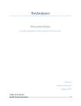
Figure 28 - Visual Representation of Possible ROS Implementation for Current System
Shown above is visual representation of how the current system may be controlled through ROS.
Each aspect of the system executes its own programs, known as nodes. The ROS allows for
communication of relevant data between these nodes through topics and services.
39
7 Conclusion
The designed system was able to demonstrate that the wheelchair can not only perform reactive
obstacle avoidance, but also utilise the Kinect sensor to make intelligent movement decisions when
locating doorways.
Although several limitations were identified a fully functional system was achieved. At the conclusion
of this project, the resulting system provides the necessary basis and foundation to develop a more
advanced wheelchair.
40
8 References
Asayesh, S. (2013). Electronic Design of Brain Controlled Wheelchair. Flinders University - School
of Computer Science, Engineering and Mathematics.
Correa, D. S., Sciotti, D. F., Prado, M. G., Sales, D. O., Wolf, D. F., & Osorio, F. S. (2012). Mobile
Robots Navigation in Indoor Environments Using Kinect Sensor. University of Sao
Paulo/IMC - SSC - LRM (Mobile Robotics Lab.).
Yanco, H. A., & Gips, J. (1997). Preliminary Investigation of a Semi-Autonomous Robotic
Wheelchair Directed Through Electrodes. RESNA Press.
41
9 Glossary
GUI
Graphical User Interface
D-POT
Digital Potentiometer
ADC, A2D
Analogue to Digital Converter
IR
Infrared Sensor
dsPIC
The microprocessor controlling the wheelchair
ROS
Robotics Operating System
IMU
Inertial Measurement Unit
DMA
Direct Memory Access
42
10 Appendices
The appendices associated with this document are in electronic form, contained within the DVD
attached to this submission.
10.1 Datasheets
dsPIC33FJx Microcontroller
dsPIC33FJx SPI module
MCP42x Digital Potentiometer
MCP3004 Analogue to Digital Converter
SHARP GP2Y0A02YK0F Infrared Sensor
MaxSonar Ultrasonic Range Finder
10.2 Code
All MATLAB code associated with the system
PIC C code: MPLABX project for running the system
10.3 Other
Thesis submission for 2013 project (Electronic Design of Brain Controlled Wheelchair, 2013)
ShopRider Jiffy user manual
43