1
Measurement Studio
Measurement Computing Edition
TM
TM
Evaluation Guide
Measurement Studio Measurement Computing Edition
October 2006
351417A-01
Support
Worldwide Technical Support and Product Information
ni.com
National Instruments Corporate Headquarters
11500 North Mopac Expressway
Austin, Texas 78759-3504
USA Tel: 512 683 0100
Worldwide Offices
Australia 1800 300 800, Austria 43 0 662 45 79 90 0, Belgium 32 0 2 757 00 20, Brazil 55 11 3262 3599,
Canada 800 433 3488, China 86 21 6555 7838, Czech Republic 420 224 235 774, Denmark 45 45 76 26 00,
Finland 385 0 9 725 725 11, France 33 0 1 48 14 24 24, Germany 49 0 89 741 31 30, India 91 80 41190000,
Israel 972 0 3 6393737, Italy 39 02 413091, Japan 81 3 5472 2970, Korea 82 02 3451 3400,
Lebanon 961 0 1 33 28 28, Malaysia 1800 887710, Mexico 01 800 010 0793, Netherlands 31 0 348 433 466,
New Zealand 0800 553 322, Norway 47 0 66 90 76 60, Poland 48 22 3390150, Portugal 351 210 311 210,
Russia 7 495 783 68 51, Singapore 1800 226 5886, Slovenia 386 3 425 42 00, South Africa 27 0 11 805 8197,
Spain 34 91 640 0085, Sweden 46 0 8 587 895 00, Switzerland 41 56 200 51 51, Taiwan 886 02 2377 2222,
Thailand 662 278 6777, United Kingdom 44 0 1635 523545
For further support information, refer to the Contacting Measurement Computing Corp. appendix. To comment
on National Instruments documentation, refer to the National Instruments Web site at ni.com/info and enter
the info code feedback.
© 2006 National Instruments Corporation. All rights reserved.
Important Information
Warranty
The media on which you receive National Instruments software are warranted not to fail to execute programming instructions, due to defects
in materials and workmanship, for a period of 90 days from date of shipment, as evidenced by receipts or other documentation. National
Instruments will, at its option, repair or replace software media that do not execute programming instructions if National Instruments receives
notice of such defects during the warranty period. National Instruments does not warrant that the operation of the software shall be
uninterrupted or error free.
A Return Material Authorization (RMA) number must be obtained from the factory and clearly marked on the outside of the package before any
equipment will be accepted for warranty work. National Instruments will pay the shipping costs of returning to the owner parts which are covered by
warranty.
National Instruments believes that the information in this document is accurate. The document has been carefully reviewed for technical accuracy. In
the event that technical or typographical errors exist, National Instruments reserves the right to make changes to subsequent editions of this document
without prior notice to holders of this edition. The reader should consult National Instruments if errors are suspected. In no event shall National
Instruments be liable for any damages arising out of or related to this document or the information contained in it.
EXCEPT AS SPECIFIED HEREIN, NATIONAL INSTRUMENTS MAKES NO WARRANTIES, EXPRESS OR IMPLIED, AND SPECIFICALLY DISCLAIMS ANY WARRANTY OF
MERCHANTABILITY OR FITNESS FOR A PARTICULAR PURPOSE. CUSTOMER’S RIGHT TO RECOVER DAMAGES CAUSED BY FAULT OR NEGLIGENCE ON THE PART OF NATIONAL
INSTRUMENTS SHALL BE LIMITED TO THE AMOUNT THERETOFORE PAID BY THE CUSTOMER. NATIONAL INSTRUMENTS WILL NOT BE LIABLE FOR DAMAGES RESULTING
FROM LOSS OF DATA, PROFITS, USE OF PRODUCTS, OR INCIDENTAL OR CONSEQUENTIAL DAMAGES, EVEN IF ADVISED OF THE POSSIBILITY THEREOF. This limitation of
the liability of National Instruments will apply regardless of the form of action, whether in contract or tort, including negligence. Any action against
National Instruments must be brought within one year after the cause of action accrues. National Instruments shall not be liable for any delay in
performance due to causes beyond its reasonable control. The warranty provided herein does not cover damages, defects, malfunctions, or service
failures caused by owner’s failure to follow the National Instruments installation, operation, or maintenance instructions; owner’s modification of the
product; owner’s abuse, misuse, or negligent acts; and power failure or surges, fire, flood, accident, actions of third parties, or other events outside
reasonable control.
Copyright
Under the copyright laws, this publication may not be reproduced or transmitted in any form, electronic or mechanical, including photocopying,
recording, storing in an information retrieval system, or translating, in whole or in part, without the prior written consent of National
Instruments Corporation.
National Instruments respects the intellectual property of others, and we ask our users to do the same. NI software is protected by copyright and other
intellectual property laws. Where NI software may be used to reproduce software or other materials belonging to others, you may use NI software only
to reproduce materials that you may reproduce in accordance with the terms of any applicable license or other legal restriction.
Trademarks
National Instruments, NI, ni.com, and LabVIEW are trademarks of National Instruments Corporation. Refer to the Terms of Use section
on ni.com/legal for more information about National Instruments trademarks.
FireWire® is the registered trademark of Apple Computer, Inc. Other product and company names mentioned herein are trademarks or trade names
of their respective companies.
Other product and company names mentioned herein are trademarks or trade names of their respective companies.
Members of the National Instruments Alliance Partner Program are business entities independent from National Instruments and have no agency,
partnership, or joint-venture relationship with National Instruments.
Patents
For patents covering National Instruments products, refer to the appropriate location: Help»Patents in your software, the patents.txt file
on your CD, or ni.com/patents.
WARNING REGARDING USE OF NATIONAL INSTRUMENTS PRODUCTS
(1) NATIONAL INSTRUMENTS PRODUCTS ARE NOT DESIGNED WITH COMPONENTS AND TESTING FOR A LEVEL OF
RELIABILITY SUITABLE FOR USE IN OR IN CONNECTION WITH SURGICAL IMPLANTS OR AS CRITICAL COMPONENTS IN
ANY LIFE SUPPORT SYSTEMS WHOSE FAILURE TO PERFORM CAN REASONABLY BE EXPECTED TO CAUSE SIGNIFICANT
INJURY TO A HUMAN.
(2) IN ANY APPLICATION, INCLUDING THE ABOVE, RELIABILITY OF OPERATION OF THE SOFTWARE PRODUCTS CAN BE
IMPAIRED BY ADVERSE FACTORS, INCLUDING BUT NOT LIMITED TO FLUCTUATIONS IN ELECTRICAL POWER SUPPLY,
COMPUTER HARDWARE MALFUNCTIONS, COMPUTER OPERATING SYSTEM SOFTWARE FITNESS, FITNESS OF COMPILERS
AND DEVELOPMENT SOFTWARE USED TO DEVELOP AN APPLICATION, INSTALLATION ERRORS, SOFTWARE AND HARDWARE
COMPATIBILITY PROBLEMS, MALFUNCTIONS OR FAILURES OF ELECTRONIC MONITORING OR CONTROL DEVICES,
TRANSIENT FAILURES OF ELECTRONIC SYSTEMS (HARDWARE AND/OR SOFTWARE), UNANTICIPATED USES OR MISUSES, OR
ERRORS ON THE PART OF THE USER OR APPLICATIONS DESIGNER (ADVERSE FACTORS SUCH AS THESE ARE HEREAFTER
COLLECTIVELY TERMED “SYSTEM FAILURES”). ANY APPLICATION WHERE A SYSTEM FAILURE WOULD CREATE A RISK OF
HARM TO PROPERTY OR PERSONS (INCLUDING THE RISK OF BODILY INJURY AND DEATH) SHOULD NOT BE RELIANT SOLELY
UPON ONE FORM OF ELECTRONIC SYSTEM DUE TO THE RISK OF SYSTEM FAILURE. TO AVOID DAMAGE, INJURY, OR DEATH,
THE USER OR APPLICATION DESIGNER MUST TAKE REASONABLY PRUDENT STEPS TO PROTECT AGAINST SYSTEM FAILURES,
INCLUDING BUT NOT LIMITED TO BACK-UP OR SHUT DOWN MECHANISMS. BECAUSE EACH END-USER SYSTEM IS
CUSTOMIZED AND DIFFERS FROM NATIONAL INSTRUMENTS’ TESTING PLATFORMS AND BECAUSE A USER OR APPLICATION
DESIGNER MAY USE NATIONAL INSTRUMENTS PRODUCTS IN COMBINATION WITH OTHER PRODUCTS IN A MANNER NOT
EVALUATED OR CONTEMPLATED BY NATIONAL INSTRUMENTS, THE USER OR APPLICATION DESIGNER IS ULTIMATELY
RESPONSIBLE FOR VERIFYING AND VALIDATING THE SUITABILITY OF NATIONAL INSTRUMENTS PRODUCTS WHENEVER
NATIONAL INSTRUMENTS PRODUCTS ARE INCORPORATED IN A SYSTEM OR APPLICATION, INCLUDING, WITHOUT
LIMITATION, THE APPROPRIATE DESIGN, PROCESS AND SAFETY LEVEL OF SUCH SYSTEM OR APPLICATION.
Contents
About This Manual
How To Use This Manual..............................................................................................viii
Conventions ...................................................................................................................ix
Chapter 1
Measurement Studio Measurement Computing Edition
Installation Instructions
Evaluating Measurement Studio on Your Machine.......................................................1-1
Installing the Current Version of Measurement Studio
over Previous Versions of Measurement Studio ..........................................1-2
Installing Measurement Studio ......................................................................................1-2
Learning More About NI and Measurement Studio ......................................................1-4
MCC Platform .................................................................................................1-4
NI Platform......................................................................................................1-4
Virtual Instrumentation ...................................................................................1-4
What Is Measurement Studio?.........................................................................1-5
Why Should I Use Measurement Studio? .......................................................1-5
Chapter 2
Measurement Studio Measurement Computing Edition
.NET Class Libraries
User Interface Controls ..................................................................................................2-1
Graph and Legend Controls.............................................................................2-4
Waveform and Scatter Graph Controls .............................................2-5
Digital Waveform Graph Control .....................................................2-6
Complex Graph Control....................................................................2-7
Numeric Controls ............................................................................................2-8
Numeric Pointer Controls .................................................................2-8
Numeric Edit Control........................................................................2-9
Boolean Controls .............................................................................................2-10
Switch and LED Controls .................................................................2-10
Additional Controls .........................................................................................2-11
Property Editor Control.....................................................................2-11
Instrument Control Strip Control.....................................................................2-12
Windows Forms Array Controls .......................................................2-14
Switch and LED Array Controls.......................................................2-14
© National Instruments Corporation
v
Measurement Studio Measurement Computing Edition
Contents
Numeric Edit Array Control ............................................................. 2-15
AutoRefresh Control......................................................................... 2-15
Analysis ......................................................................................................................... 2-16
Common ........................................................................................................................ 2-17
Network Variable .......................................................................................................... 2-17
Hardware Connectivity.................................................................................................. 2-18
Data Acquisition ............................................................................................. 2-18
Universal Library.............................................................................. 2-18
MccDaq Scan Components .............................................................. 2-19
Instrument Control .......................................................................................... 2-19
MCC-488.2 ....................................................................................... 2-19
Measurement Studio Integration with Visual Studio .................................................... 2-20
Measurement Studio Menu ............................................................................. 2-20
Creating a Measurement Studio Project.......................................................... 2-21
Chapter 3
Getting Started with Measurement Studio
Measurement Computing Edition
Walkthrough: Creating a Measurement Studio MCC DAQ Application
in Visual Studio 2003 ................................................................................................. 3-1
Before You Begin ........................................................................................... 3-2
Walkthrough: Creating a Measurement Studio MCC DAQ Scan Components
Application in Visual Studio 2003 ............................................................................. 3-8
Before You Begin ........................................................................................... 3-9
Walkthrough: Creating a Measurement Studio MCC 488.2 Application
in Visual Studio 2003 ................................................................................................. 3-17
Before You Begin ........................................................................................... 3-17
Measurement Studio Walkthroughs for Visual Studio 2005......................................... 3-22
Walkthrough: Creating a Measurement Studio Application
with Windows Forms Controls and Analysis in Visual Studio 2005 ......................... 3-22
Walkthrough: Creating a Measurement Studio Application
with Web Forms Controls and Analysis in Visual Studio 2005................................. 3-31
Creating a Measurement Studio Application with Web Forms Controls
and Network Variable in Visual Studio 2005............................................................. 3-40
Appendix A
Technical Support and Professional Services
Glossary
Index
Measurement Studio Measurement Computing Edition
vi
ni.com
About This Manual
The Measurement Studio Measurement Computing Evaluation Guide
introduces the concepts associated with the Measurement Studio class
libraries and development tools. This guide assumes that you have a general
working knowledge of Microsoft Visual Studio, including .NET Windows,
and ASP.NET.
How To Use This Manual
The Measurement Studio Measurement Computing Evaluation package
contains the Measurement Studio evaluation software. Any applications
you build with the Measurement Studio Evaluation package have a 30-day
evaluation period.
Measurement Studio includes support for Visual Studio .NET 2003 and
Visual Studio 2005. The Measurement Studio Visual Studio .NET 2003 and
Visual Studio 2005 CD includes separate, parallel sets of class libraries,
integration features, and support documentation for developing with Visual
Studio .NET 2003 and Visual Studio 2005. This manual documents the
Visual Studio .NET 2003 and Visual Studio 2005 CD.
The Measurement Studio Measurement Computing Evaluation Guide
is organized into three chapters. Chapter 1, Measurement Studio
Measurement Computing Edition Installation Instructions, is an overview
of Measurement Computing, National Instruments, virtual instrumentation,
and Measurement Studio. This chapter includes installation requirements
and installation and evaluation instructions. Chapter 2, Measurement
Studio Measurement Computing Edition .NET Class Libraries, includes
information about Measurement Studio features and functionality.
Chapter 3, Getting Started with Measurement Studio Measurement
Computing Edition, includes walkthroughs that guide you through
step-by-step instructions on how to develop with Measurement Studio
features.
Use this guide as a starting point to learn about Measurement Studio. Refer
to the NI Measurement Studio Help within the Visual Studio environment
for function reference and detailed information about the Measurement
Studio class libraries, wizards, assistants, and other features.
© National Instruments Corporation
vii
Measurement Studio Measurement Computing Edition
About This Manual
Conventions
The following conventions appear in this manual:
<>
Text enclosed in angle brackets represents directory names and parts of
paths that may vary on different computers, such as <Windows\System>.
[]
Square brackets enclose optional items—for example, [response].
»
The » symbol leads you through nested menu items and dialog box options
to a final action. The sequence File»Page Setup»Options directs you to
pull down the File menu, select the Page Setup item, and select Options
from the last dialog box.
This icon denotes a tip, which alerts you to advisory information.
This icon denotes a note, which alerts you to important information.
bold
Bold text denotes items that you must select or click on in the software,
such as menu items and dialog box options. Bold text also denotes class
library member names or emphasis.
italic
Italic text denotes parameters, variables, cross-references, or an
introduction to a key concept. Italic text also denotes text that is a
placeholder for a word or value that you must supply.
monospace
Text in this font denotes text or characters that you should enter from the
keyboard, sections of code, programming examples, and syntax examples.
This font is also used for the proper names of disk drives, paths, directories,
programs, subprograms, subroutines, device names, functions, operations,
variables, filenames, and extensions.
Measurement Studio Measurement Computing Edition
viii
ni.com
Measurement Studio
Measurement Computing
Edition Installation Instructions
1
Evaluating Measurement Studio on Your Machine
The following sections contain information and instructions for installing
the Measurement Studio Evaluation Package.
Note Any applications you build with the Measurement Studio Evaluation package have
a thirty day evaluation period.
To use Measurement Studio, your computer must have the following:
•
Microsoft Windows 2000/XP
•
Microsoft .NET Framework 1.1 for Visual Studio .NET 2003 or
Microsoft .NET Framework 2.0 for Visual Studio 2005
•
Standard, Professional, Enterprise Developer, Enterprise Architect, or
Academic edition of Microsoft Visual Studio .NET 2003 or Microsoft
Visual Studio 2005
•
Intel Pentium II class processor, 733 MHz or higher
•
Video display—800 × 600, 256 colors (16-bit color recommended for
user interface controls)
•
Minimum of 256 MB of RAM (512 MB or higher recommended)
•
Minimum of 405 MB of free hard disk space for Visual Studio .NET
2003 support and minimum of 385 MB of free hard disk space for
Visual Studio 2005 support
•
Microsoft-compatible mouse
•
Microsoft Internet Explorer 6.0 or later
Optional Installation—In order for links from Measurement Studio help
topics to .NET Framework help topics to work, you must install the
© National Instruments Corporation
1-1
Measurement Studio Measurement Computing Edition
Chapter 1
Measurement Studio Measurement Computing Edition Installation Instructions
Microsoft .NET Framework SDK 1.1 or Microsoft .NET Framework
SDK 2.0.
Installing the Current Version of Measurement Studio over Previous
Versions of Measurement Studio
You can have only one version of Measurement Studio installed on a
system for each version of Visual Studio or the .NET Framework installed
on the system. For example, you can have Measurement Studio 8.0.1 for
Visual Studio .NET 2003 installed on the same system as Measurement
Studio 8.1 for Visual Studio 2005, but you cannot have Measurement
Studio 8.0.1 for Visual Studio 2005 installed on the same system as
Measurement Studio 8.1 for Visual Studio 2005.
If you install a newer version of Measurement Studio on a machine that has
a prior version of Measurement Studio installed, the newer version installer
replaces the prior version functionality, including class libraries. However,
the prior version assemblies remain in the global assembly cache (GAC);
therefore, applications that reference the prior version continue to use the
prior version .NET assemblies.1
Installing Measurement Studio
Complete the following steps to install Measurement Studio. These steps
describe a typical installation. Please carefully review all additional
licensing and warning dialog boxes.
1.
Insert the Measurement Studio CD into the CD drive. autorun.exe
automatically starts. If it does not automatically start, double-click the
autorun.exe icon.
2.
Click Next to install all NI software to the default installation
directory, or click Browse to select a different installation directory.
Click Next.
Note The option to browse for an installation location is valid only if you have not already
installed any Measurement Studio features for the version of Visual Studio that you are
installing. If you have any Measurement Studio features installed, then Measurement
Studio installs to the same root directory to which you installed other Measurement Studio
features.
1
This does not apply to NationalInstruments.Common.dll. NationalInstruments.Common.dll uses a publisher policy
file to redirect applications to always use the newest version of NationalInstruments.Common.dll installed on the
system, for each version of the .NET Framework. NationalInstruments.Common.dll is backward compatible.
Measurement Studio Measurement Computing Edition
1-2
ni.com
Chapter 1
Measurement Studio Measurement Computing Edition Installation Instructions
3.
From the feature tree, select the features you want to install. To change
the Measurement Studio installation directory, select the first feature in
the list and click Browse. You must install Measurement Studio to a
local drive. If you install Measurement Studio support for more than
one version of Visual Studio, install them to different directories. Click
Next.
4.
Review the license agreement and select I accept the License
Agreement(s). Click Next.
5.
In the Installation Summary dialog box, review the features you
selected. Click Next.
Note Step 6 starts the installation of Measurement Studio. Be aware that when the installer
indicates that it is removing backup files, this is a normal operation. The installer may take
several minutes to complete this step.
6.
In the Installation Summary dialog box, review the features you
selected. Click Next.
Note Step 8 starts the installation of Measurement Studio. Be aware that when the installer
indicates that it is removing backup files, this is a normal operation. The installer may take
several minutes to complete this step.
7.
In the MCC Drivers for Measurement Studio dialog box, select the
Device Drivers components you want to install. Click Install.
8.
If you choose to install InstaCal and Universal Library, continue with
the following steps. If not, skip to step 13. In the Welcome to InstaCal
and Universal Library dialog box, click Next.
9.
In the Destination Folder dialog box, click Next to install InstaCal and
Universal Library to the default location or click Change to install to
a different location.
10. In the Ready to Install dialog box, click Install to install InstaCal and
Universal Library.
11. Click Finish.
12. If you choose to install GPIB-488, continue with the following steps.
If not, skip to step 19. In the GPIB-488 Installation Wizard, select
Next.
13. Review the license agreement and select I accept the License
Agreement(s). Click Next.
© National Instruments Corporation
1-3
Measurement Studio Measurement Computing Edition
Chapter 1
Measurement Studio Measurement Computing Edition Installation Instructions
14. In the Destination Folder dialog box, click Next to install GPIB-488 to
the default location or click Browse to install the driver to a different
location.
15. In the Select Features dialog box, select the features you want to
install. Click Next.
16. Click Next to start the installation.
17. Click Finish to complete the installation.
18. In the Installation Summary dialog box, review the features you
selected. Click Next.
19. Click Finish to complete the installation.
20. If prompted, click the appropriate restart option. If you did not install
a component that requires a restart, you will not be prompted to restart.
Learning More About NI and Measurement Studio
MCC Platform
The mission of Measurement Computing Corporation is to provide our
customers with PC-based data acquisition hardware and software that will
save time and save money.
NI Platform
National Instruments is committed to providing software and hardware
for engineers and scientists who develop measurement and automation
applications. NI provides high performance, tight integration, and rapid
application development of virtual instruments at a lower cost than
traditional measurement instruments.
Virtual Instrumentation
Virtual instruments represent a fundamental shift from traditional
hardware-centered instrumentation systems to software-centered systems
that exploit the computing power, productivity, display, and connectivity
capabilities of popular desktop computers and workstations. With virtual
instruments, engineers and scientists build user-defined measurement and
automation systems that suit their needs exactly, instead of being limited by
traditional vendor-defined instruments.
Measurement Studio Measurement Computing Edition
1-4
ni.com
Chapter 1
Measurement Studio Measurement Computing Edition Installation Instructions
What Is Measurement Studio?
Measurement Studio is the software tool for creating virtual instruments
with Microsoft Visual Studio. Measurement Studio is an integrated suite of
tools and class libraries that are designed for developers using Microsoft
.NET Windows and ASP.NET to develop measurement and automation
applications.
This evaluation package includes Measurement Studio tools for Visual C#
and Visual Basic .NET.
Tip As you work through this manual, you will see italicized references to relevant
Measurement Studio help topics. To find these topics, use the table of contents in the
NI Measurement Studio Help.
Why Should I Use Measurement Studio?
Measurement Studio is an integrated suite of tools and class libraries that
are designed for developers using Microsoft Visual Basic .NET, Visual C#,
and ASP.NET to develop measurement and automation applications.
Measurement Studio dramatically reduces application development time
through object-oriented measurement hardware interfaces, advanced
analysis libraries, scientific user interface controls for Windows and Web
applications, measurement data networking, wizards, interactive code
designers, and highly extensible .NET classes. You can use Measurement
Studio to develop a complete measurement and automation application that
includes data acquisition, analysis, and presentation functionalities.
© National Instruments Corporation
1-5
Measurement Studio Measurement Computing Edition
Measurement Studio
Measurement Computing
Edition .NET Class Libraries
2
This chapter provides overview information about features and
functionality included in Measurement Studio 8.1 support for Visual Studio
.NET 2003 and Visual Studio 2005. Refer to the NI Measurement Studio
Help for detailed information about these features. Refer to Chapter 3,
Getting Started with Measurement Studio Measurement Computing
Edition, for step-by-step instructions on developing Measurement Studio
applications.
Measurement Studio includes the following features and functionality:
•
User Interface controls
•
Analysis class libraries
•
Common class library
•
Data acquisition
•
Instrument control
•
Integration into the Visual Studio environment
User Interface Controls
Measurement Studio includes managed .NET user interface Windows
Forms and Web Forms controls designed specifically for test and
measurement applications.
The Measurement Studio ASP.NET Web Forms controls are designed to
provide a rich user interface experience through the web browser. The
browsers are divided into two broad categories: uplevel and downlevel.
Uplevel browsers include recent versions of Microsoft Internet Explorer
and Mozilla Firefox. All other browsers are downlevel browsers.
By using Measurement Studio controls, you can focus on creating an end
solution instead of developing UI components.
© National Instruments Corporation
2-1
Measurement Studio Measurement Computing Edition
Chapter 2
Measurement Studio Measurement Computing Edition .NET Class Libraries
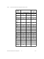
User
Interface
Controls
Visual Studio 2005
Visual Studio
2003
Windows
Forms
Web Forms
Windows
Forms
Waveform
graph
✔
✔
✔
Scatter graph
✔
✔
✔
Digital
waveform
graph
✔
✔
✔
Complex
graph
✔
✔
✔
Legend
✔
✔
✔
Knob
✔
✔
✔
Gauge
✔
✔
✔
Meter
✔
✔
✔
Slide
✔
✔
✔
Thermometer
✔
✔
✔
Tank
✔
✔
✔
Numeric edit
✔
✔
✔
Switch
✔
✔
✔
LED
✔
✔
✔
Property editor
✔
Array controls
✔
✔
AutoRefresh
control
✔
Instrument
control strip
Measurement Studio Measurement Computing Edition
✔
2-2
ni.com
Chapter 2
Measurement Studio Measurement Computing Edition .NET Class Libraries
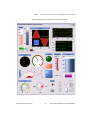
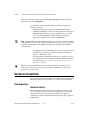
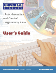
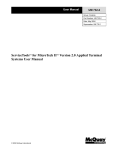
The following figure shows the Measurement Studio controls.
© National Instruments Corporation
2-3
Measurement Studio Measurement Computing Edition
Chapter 2
Measurement Studio Measurement Computing Edition .NET Class Libraries
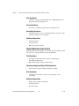
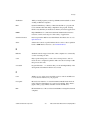
Graph and Legend Controls
Measurement Studio includes four graphs: the waveform graph, the scatter
graph, the digital waveform graph, and the complex graph. Use the graphs
to display data in the application type you need.
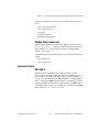
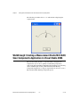
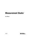
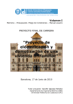
You can use the Measurement Studio waveform graph and scatter graph
controls, as shown in Figure 2-1, to display two-dimensional data on a
Windows Forms user interface or in a Web browser. Use the waveform
graph to display two-dimensional linear data. You explicitly specify
each value in one dimension and provide an initial value and interval to
implicitly specify the values in the other dimension. You can use the scatter
graph to display two-dimensional linear or nonlinear data by explicitly
specifying each value in both dimensions.
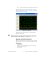
Figure 2-1. Waveform Graph with Cursors and Scatter Graph with XY Point
Annotation; Both Graphs Have Corresponding Legends
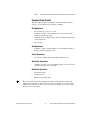
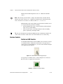
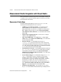
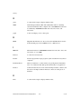
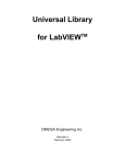
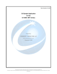
You can use the Measurement Studio digital waveform graph control, as
shown in Figure 2-2, to display DigitalWaveform data on a Windows
Forms user interface or in a Web browser. You can use the Measurement
Studio complex graph control to display ComplexDouble data on a
Windows Forms user interface or in a Web browser. A ComplexDouble
number consists of a real part and an imaginary part. You can use the
Measurement Studio Measurement Computing Edition
2-4
ni.com
Chapter 2
Measurement Studio Measurement Computing Edition .NET Class Libraries
Measurement Studio legend control, as shown in Figure 2-1, to display
symbols and descriptions for a specific set of elements of another object,
such as the plots or cursors of a graph.
Figure 2-2. .NET Digital Graph
The following sections list the operations you can perform with the
Measurement Studio graphs.
Note The following sections include a sample of the functionality available with the
graph controls; however, for a complete list of graph control functionality, refer to the
Measurement Studio User Manual online at ni.com/manuals.
Waveform and Scatter Graph Controls
With the waveform graph and scatter graph controls and the classes that
interface with the controls, you can perform many operations, including:
Plot Operations
•
Plot and chart data.
•
Configure a graph to contain multiple plots to show separate but
related data on the same graph.
•
Plot error bands.
© National Instruments Corporation
2-5
Measurement Studio Measurement Computing Edition
Chapter 2
Measurement Studio Measurement Computing Edition .NET Class Libraries
Axis Operations
•
Configure a graph to include multiple axes or independent ranges so
that plot data fits the graph plot area.
Cursor Operations
•
Use cursors to identify key points in plots and the plot area.
Annotation Operations
•
Configure text labels, arrows, and drawing shapes to annotate a point
anywhere in the plot area of the graph.
Additional Operations
•
Zoom interactively.
•
Pan interactively.
•
Edit axis ranges interactively.
Digital Waveform Graph Control
With the digital waveform graph control and the classes that interface with
the control, you can perform many operations, including:
Plot Operations
•
Plot digital waveform data. Data values can represent up to
eight different digital states.
•
Expand and collapse signal plots interactively.
Waveform Sample and Signal State Operations
•
Create custom waveform sample and signal state labels.
Axis Operations
•
Configure the axis modes to fixed, exact autoscaling, or loose
autoscaling.
Additional Operations
•
Display data in sample or time mode.
•
Zoom interactively.
•
Pan interactively.
Measurement Studio Measurement Computing Edition
2-6
ni.com
Chapter 2
Measurement Studio Measurement Computing Edition .NET Class Libraries
Complex Graph Control
With the complex graph control and the classes that interface with the
control, you can perform many operations, including:
Plot Operations
•
Plot and chart ComplexDouble data.
•
Configure a graph to contain multiple plots to show separate but
related data on the same graph.
•
Configure the plot to display arrows. The arrows indicate the direction
of the complex data.
•
Plot error data.
Axis Operations
•
Configure a graph to include multiple axes or independent ranges so
that plot data fits the graph plot area.
Cursor Operations
•
Use cursors to identify key points in plots and the plot area.
Annotation Operations
•
Configure text labels, arrows, and drawing shapes to annotate a point
anywhere in the plot area of the graph.
Additional Operations
•
Zoom interactively.
•
Pan interactively.
•
Edit axis ranges interactively.
Tip For more information about using the waveform, scatter, digital waveform, and
complex graph and legend controls, refer to the Using the Measurement Studio Graph
.NET Controls and Using the Measurement Studio Legend .NET Control sections in the
NI Measurement Studio Help.
© National Instruments Corporation
2-7
Measurement Studio Measurement Computing Edition
Chapter 2
Measurement Studio Measurement Computing Edition .NET Class Libraries
Numeric Controls
Numeric Pointer Controls
Use the Measurement Studio numeric controls to display numerical
information with the look of scientific instruments on a Windows Forms
user interface and in an ASP.NET Web application. The numeric controls
include a knob, gauge, meter, slide, thermometer, and tank. The following
sections describe operations available with the controls and the classes that
interface with them.
Note The following sections include a sample of the functionality available with the
numeric controls; however, for a complete list of numeric control functionality, refer to the
Measurement Studio User Manual online at ni.com/manuals.
With the numeric controls and the classes that interface with them, you can
perform many operations, including:
•
Configure the scale to be linear or logarithmic and toggle the visibility
of the scale.
•
Fill the scale and configure the range, color, dimensions, and style of
the fill.
•
Connect to the Measurement Studio .NET numeric edit control so that
if you change the value of one control, it changes the value of the other
control.
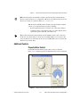
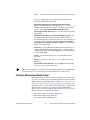
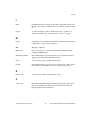
Use the Measurement Studio knob, gauge, and meter controls, as shown in
Figure 2-3, to input and display numeric data on your user interface.
Figure 2-3. Knob, Gauge, and Meter .NET Controls
Measurement Studio Measurement Computing Edition
2-8
ni.com
Chapter 2
Measurement Studio Measurement Computing Edition .NET Class Libraries
With the knob, gauge, and meter controls and the classes that interface with
the controls, you can perform many operations, including:
•
Specify the start and sweep angle of the arc programmatically or from
the Properties window.
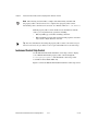
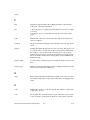
Use the Measurement Studio slide, tank, and thermometer controls, as
shown in Figure 2-4, to input and display numeric data on your interface.
Figure 2-4. Slide, Tank, and Thermometer .NET Controls
With the slide, tank, and thermometer controls and the classes that interface
with them, you can perform many operations, including:
•
Fill to the minimum or maximum value of the scale.
•
Position the scale horizontally with left, right, or both and position the
scale vertically with top, bottom, or both.
Tip For more information about using the Windows Forms and Web Forms knob, gauge,
meter, slide, tank, or thermometer controls, refer to the Knob, Gauge, Meter, Slide, Tank,
or Thermometer Class sections in the NI Measurement Studio Help.
Numeric Edit Control
Use the Measurement Studio numeric edit control to display numeric
values and to provide a way by which end users can edit numeric values.
Typically, you use a numeric edit control to input or display double
numerical data instead of using a Windows Forms TextBox control,
© National Instruments Corporation
2-9
Measurement Studio Measurement Computing Edition
Chapter 2
Measurement Studio Measurement Computing Edition .NET Class Libraries
Windows Forms NumericUpDown control, or a Web Forms TextBox
control.
Note The following section includes a sample of the functionality available with the
numeric edit control; however, for a complete list of numeric edit control functionality,
refer to the Measurement Studio User Manual online at ni.com/manuals.
With the numeric edit control and the classes that interface with the control,
you can perform many operations, including:
•
Set the minimum range value to negative infinity and the maximum
range value to positive infinity.
•
Create custom formats or use built-in numeric formats including
generic, engineering, and simple double.
Tip For more information about using the Windows Forms or Web Forms numeric edit
control, refer to the NumericEdit Class section in the NI Measurement Studio Help.
Boolean Controls
Switch and LED Controls
Use the Measurement Studio switch and LED controls as Boolean controls
on a Windows Forms or Web Forms user interface. You typically use a
switch control, as shown in Figure 2-5, to receive and control Boolean input
on an application user interface.
Figure 2-5. Switch Control in Vertical Toggle 3D Style
You typically use an LED control, as shown in Figure 2-6, to indicate a
Boolean value on an application user interface.
Figure 2-6. LED Control in Square 3D Style
Measurement Studio Measurement Computing Edition
2-10
ni.com
Chapter 2
Measurement Studio Measurement Computing Edition .NET Class Libraries
Note The following section includes a sample of the functionality available with the
Boolean controls; however, for a complete list of Boolean control functionality, refer to the
Measurement Studio User Manual online at ni.com/manuals.
With the switch and LED controls and the classes that interface with the
controls, you can perform many operations, including:
•
Receive notification before or after the state of the control changes.
•
Configure how the control behaves when you click it with the mouse
or press the spacebar when the control has focus.
Tip For more information about using the switch and LED controls, refer to the Using
the Measurement Studio Windows Forms Switch and LED .NET Controls section or the
Using the Measurement Studio Web Forms Switch and LED .NET Controls section in the
NI Measurement Studio Help.
Additional Controls
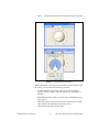
Property Editor Control
Use the Measurement Studio property editor control, as shown in
Figure 2-7, to configure properties for Windows Forms controls at run time.
Figure 2-7. Property Editor Control for the Knob Control Scale Arc Property
© National Instruments Corporation
2-11
Measurement Studio Measurement Computing Edition
Chapter 2
Measurement Studio Measurement Computing Edition .NET Class Libraries
Note The following section includes a sample of the functionality available with
the property editor control; however, for a complete list of property editor control
functionality, refer to the Measurement Studio User Manual online at ni.com/manuals.
With the property editor control and the classes that interface with the
control, you can perform many operations, including:
•
Edit any .NET type at run time, including collections.
•
Edit expandable properties that represent nested properties of another
object, such as major divisions of an axis.
Tip For more information about using the property editor control, refer to the Using the
Measurement Studio Property Editor Control topic in the NI Measurement Studio Help.
Instrument Control Strip Control
Use the Measurement Studio instrument control strip control to display
a set of Measurement Studio property editor controls through the
ToolStripPropertyEditor. The instrument control strip control
is available in Visual Studio 2005 only.
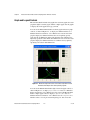
Figure 2-8 shows the Measurement Studio instrument control strip control.
Measurement Studio Measurement Computing Edition
2-12
ni.com
Chapter 2
Measurement Studio Measurement Computing Edition .NET Class Libraries
Figure 2-8. Instrument Control Strip Control
With the instrument control strip control and the classes that interface with
the control, you can perform the following operations:
•
Use the instrument control strip control as a toolbar for editing
property values of another control through the associated editors at
run time.
•
Edit multiple property values of controls with one instrument control
strip control.
•
Add other types of controls, such as the tool strip button or tool strip
label control, to the instrument control strip control.
•
Customize the appearance of the control.
© National Instruments Corporation
2-13
Measurement Studio Measurement Computing Edition
Chapter 2
Measurement Studio Measurement Computing Edition .NET Class Libraries
Tip For more information, refer to the Using the Instrument Control Strip Control topic in
the NI Measurement Studio Help.
Windows Forms Array Controls
You can create an array of Measurement Studio controls that behave as a
single unit. For example, you can use these array controls to visualize and
control ports of a digital line or values of an array. Measurement Studio
includes switch, LED, and numeric edit array controls. You can create
control arrays of other controls if those controls meet the constraints of the
generic type parameter TControl. The Windows Forms array controls are
available in Visual Studio 2005 only.
Note The following sections include a sample of the functionality available with the array
controls; however, for a complete list of array control functionality, refer to the
Measurement Studio User Manual online at ni.com/manuals.
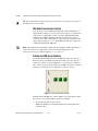
Switch and LED Array Controls
Use the Measurement Studio switch and LED array controls as an array of
Boolean controls on a Windows Forms user interface. You typically use a
switch array control, as shown in Figure 2-9, to control ports of a digital
line or values of an array. You typically use an LED array control, as shown
in Figure, to visualize ports of a digital line or values of an array.
Figure 2-9. Switch and LED Array Controls
With the switch and LED array controls and the classes that interface with
the controls, you can perform many operations, including:
•
Set values by passing an array of data.
•
Modify the number of controls displayed based on the length of the
specified values.
Measurement Studio Measurement Computing Edition
2-14
ni.com
Chapter 2
Measurement Studio Measurement Computing Edition .NET Class Libraries
Tip For more information about using the switch and LED array controls, refer to the
Using the Measurement Studio Control Array .NET Controls topic in the NI Measurement
Studio Help.
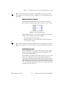
Numeric Edit Array Control
Use the Measurement Studio numeric edit array control, as shown in
Figure 2-10 to control and visualize values of an array of double values.
Figure 2-10. Numeric Edit Array Control
With the numeric edit array control and the classes that interface with the
control, you can perform many operations, including:
•
Set values by passing an array of data.
•
Modify the number of controls displayed based on the length of the
array of values you specify.
Tip For more information about using the numeric edit array control, refer to the Using
the Measurement Studio Control Array .NET Controls topic in the NI Measurement Studio
Help.
AutoRefresh Control
Use the AutoRefresh control to update a Web control or a group of Web
controls on the client at a specified interval. The AutoRefresh control is
available in Visual Studio 2005 only.
The AutoRefresh control renders JavaScript on the client to create a timer
in the browser. When the timer elapses, the AutoRefresh updates the
controls in the AutoRefresh group. For down-level browsers, the controls
update when the page posts back to the server. If the client browser supports
client callbacks, the client-side script rendered by the AutoRefresh control
uses a client callback to update the associated controls on the client without
posting the page back to the server.
© National Instruments Corporation
2-15
Measurement Studio Measurement Computing Edition
Chapter 2
Measurement Studio Measurement Computing Edition .NET Class Libraries
Analysis
The Measurement Studio Analysis .NET class library is in the
NationalInstruments.Analysis namespace. The Analysis class
library includes a set of classes that provides various digital signal
processing, signal filtering, signal generation, peak detection, and other
general mathematical functionality. Use this library to analyze acquired
data or to generate data.
The Analysis class library includes the following functionality:
•
Sawtooth, sine, square, triangle, and basic function wave generators
•
Bessel, Chebyshev, Inverse Chebyshev, Windowed, Kaiser, and
Elliptic Low, High, Bandpass, and Bandstop filters
•
Signal processing functions such as convolution, deconvolution,
correlation, decimation, integration, and differentiation
•
FFT, Inverse FFT, Real FFT, Fast Hartley, Inverse Fast Hartley, Fast
Hilbert, Inverse Fast Hilbert, DST, Inverse DST, DCT, and Inverse
DCT transformations
•
Linear algebra functions such as determinant, check positive
definiteness, calculate dot product, and other various matrix functions
•
Scaled and unscaled windowing classes
•
Common statistical functions such as mean, median, mode, and
variance
•
Exponential, linear, and polynomial curve fitting functions
•
Signal generation functions
Tip For more information about analyzing or generating data with the Analysis class
library, refer to the Using the Measurement Studio Analysis .NET Library topic in the NI
Measurement Studio Help. For more information about the functionality included in the
Analysis class library, visit ni.com/analysis and select Analysis in Measurement
Studio.
Measurement Studio Measurement Computing Edition
2-16
ni.com
Chapter 2
Measurement Studio Measurement Computing Edition .NET Class Libraries
Common
The Measurement Studio Common .NET class library is in the
NationalInstruments namespace. The Common class library provides
a set of classes that facilitates the exchange of data between the acquisition,
analysis, and user interface portions of your application. The Common
class library includes the following features:
•
A ComplexDouble data type. This data type represents a complex
number of type Double that is composed of a real part and an
imaginary part.
•
A DigitalWaveform data type. This data type represents a set of
digital states that are grouped by samples or signals.
•
An AnalogWaveform data type. This data type represents an analog
signal that varies over time.
•
A DataConverter class that converts data from one data type to
another data type, such as converting an array of integers to an array
of doubles.
•
An EngineeringFormatInfo class that defines a custom formatter
to format numeric values as strings with engineering notation and
International System of Units (SI) prefixes and symbols.
•
A PrecisionWaveformTiming class that you can use to represent
the timing of an analog or digital waveform that is accurate to the
nearest 2-64 second. PrecisionWaveformTiming is available only in
Measurement Studio support for Visual Studio 2005.
Tip For more detailed information about the Common class library, refer to the
NationalInstruments section in the NI Measurement Studio Help.
Network Variable
The Measurement Studio Network Variable .NET class library includes
three namespaces: NationalInstruments.NetworkVariable,
NationalInstruments.NetworkVariable.WindowsForms, and
NationalInstruments.NetworkVariable.WebForms. Use the
Network Variable class library to transfer live measurement data between
applications and servers over the network.
Note The Network Variable class library is intended to supersede the Measurement Studio
DataSocket .NET class library. The Measurement Studio DataSocket .NET library is not
available from the Toolbox in Visual Studio 2005. However, you can add DataSocket back
© National Instruments Corporation
2-17
Measurement Studio Measurement Computing Edition
Chapter 2
Measurement Studio Measurement Computing Edition .NET Class Libraries
to the Toolbox. Right-click the Toolbox. Select Choose Items. In the Choose Toolbox
Items dialog box, select DataSocket.
Use the features in the Network Variable class library to perform the
following operations:
•
Exchange different types of data between Measurement Studio,
LabVIEW, LabWindows™/CVI™, and other applications that support
NI-Publish Subscribe Protocol (psp:) and OLE for Process Control
(opc:) servers. Exchanging data between Measurement Studio
applications and OPC servers requires LabVIEW DSC.
Note Measurement Studio and LabWindows/CVI refer to variables as network variables
and LabVIEW refers to variables as shared variables. However, you can read to and write
from Measurement Studio and LabWindows/CVI network variables with LabVIEW
shared variables.
•
Use Windows Forms and Web Forms data sources to expose Network
Variable data items that you can bind to properties of a Windows
Forms or a Web Forms control.
•
Use the Network Variable Browser dialog box to quickly locate and
select data items on other computers and servers. The Browser Dialog
is included in the NationalInstruments.NetworkVariable.
WindowsForms class.
Tip For more detailed information about the Network Variable class library, refer
to the Using the Meausrement Studio Network Variable .NET Library section in the
NI Measurement Studio Help.
Hardware Connectivity
NI is committed to providing seamless connectivity for data acquisition and
instrument control devices, allowing you to quickly take measurements.
Data Acquisition
Universal Library
The Measurement Studio Universal Library .NET class library is in the
MccDaq namespace. This class library is included when you install the
Universal Library driver. Use the Universal Library class library to
communicate with and control Measurement Computing data acquisition
(DAQ) devices.
Measurement Studio Measurement Computing Edition
2-18
ni.com
Chapter 2
Measurement Studio Measurement Computing Edition .NET Class Libraries
Use the Universal Library class library to perform the following types of
tasks:
•
Analog signal measurement
•
Analog signal generation
•
Digital I/O
•
Counting and timing
•
Temperature measurement
MccDaq Scan Components
The Measurement Studio Scan Components .NET class library is in the
MccDaq.ScanComponents namespace. The MccDaq Scan Components
library includes a set of components for reading and writing multiple
channels of analog data.
Use the MccDaq Scan Components library to perform the following types
of tasks:
•
Analog input scans
•
Analog output scans
Instrument Control
MCC-488.2
The Measurement Studio MCC-488.2 .NET class library is in the
MccDaq.Mcc4882namespace. This class library is included when you
install the MCC-488.2 driver. The MCC-488.2 class library includes a set
of classes for communicating with GPIB instruments, controlling GPIB
devices, and acquiring GPIB status information. Use this library to design
code that communicates with and controls instruments on a GPIB interface.
Use the MCC-488.2 class library to configure and communicate with GPIB
devices using the Device and Board classes.
© National Instruments Corporation
2-19
Measurement Studio Measurement Computing Edition
Chapter 2
Measurement Studio Measurement Computing Edition .NET Class Libraries
Measurement Studio Integration with Visual Studio
Measurement Studio seamlessly integrates into Visual Studio, allowing you
to quickly create test and measurement applications without ever leaving
the Visual Studio environment.
Measurement Studio Menu
The Measurement Studio Menu provides an easy way to access the
following National Instruments resources and tools:
•
Add/Remove Class Libraries Wizard—Use the Measurement
Studio Add/Remove Class Libraries wizard to add or remove
Measurement Studio class libraries or assemblies in existing Visual
Basic .NET and Visual C# projects. Select Measurement Studio»
View .NET Class Library Wizard to access this menu item in Visual
Studio 2005.
•
Measurement Computing»InstaCal—Use InstaCal to configure,
calibrate, and test MCC hardware.
•
MCC Tools»GPIBConfig—Use GPIBConfig to configure MCC
GPIB hardware. Select MCC Tools»GPIBConfig to access this menu
item in Visual Studio 2005.
•
Discussion Forums—Use the NI Discussion Forums at
forums.ni.com to participate in discussion forums and exchange
code with measurement and automation developers around the world.
Select Measurement Studio Online Resources»Discussion Forums
to access this menu item in Visual Studio 2005.
•
Instrument Driver Network—Use the NI Instrument Driver Network
at ni.com/idnet as a central resource for downloading, developing,
and submitting instrument drivers. Select Measurement Studio
Online Resources»Instrument Driver Network to access this menu
item in Visual Studio 2005.
•
Search Technical Support—Use NI Technical Support at ni.com/
support to find support resources available for most products,
including software drivers and updates, KnowledgeBase articles,
product manuals, step-by-step troubleshooting wizards, conformity
documentation, example code, tutorials and application notes,
instrument drivers, discussion forums, and a measurement glossary.
Select Measurement Studio Online Resources»Search Technical
Support to access this menu item in Visual Studio 2005.
•
NI Measurement Studio Help—Use the NI Measurement Studio
Help to access detailed Measurement Studio help, including function
Measurement Studio Measurement Computing Edition
2-20
ni.com
Chapter 2
Measurement Studio Measurement Computing Edition .NET Class Libraries
reference, walkthroughs, and conceptual topic documentation on
developing with Measurement Studio.
•
Additional Online Resources»Measurement Studio Home
Page—Use the Measurement Studio Web site at ni.com/mstudio to
find Measurement Studio news, support, downloads, and evaluation
software. Select Measurement Studio Online Resources»
Measurement Studio Home Page to access this menu item in Visual
Studio 2005.
•
Additional Online Resources»Measurement Encyclopedia—Use
the online NI Measurement Encyclopedia to find information on
measurement principles, standards organizations, and a wide range of
technology and measurement terms. Select Measurement Studio
Online Resources»Measurement Encyclopedia to access this menu
item in Visual Studio 2005.
•
Preferences—Use the Measurement Studio Preferences dialog box to
configure Measurement Studio settings, such as conversion options
and add-in preferences. Select Tools»Options to access this menu item
in Visual Studio 2005.
•
Patents—Use the Patents dialog box to view information about
NI patents.
•
Licenses—Use the Licenses dialog box to view information about
NI licenses.
•
About NI Measurement Studio—Use the NI Measurement Studio
About box to view version information.
Tip For more information about the resources included in the Measurement Studio Menu,
refer to the Measurement Studio Menu topic in the NI Measurement Studio Help.
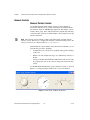
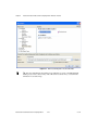
Creating a Measurement Studio Project
Measurement Studio includes class library and application templates that
you can use to quickly create measurement applications with Visual Basic
.NET, Visual C#, and ASP.NET. Refer to Chapter 3, Getting Started with
Measurement Studio Measurement Computing Edition, for step-by-step
instructions on how to create a Measurement Studio project. Use the Visual
Studio New Project dialog box, as shown for Visual Studio 2005 in
Figure 2-11, to access these templates and to create projects. You can create
the following projects in Measurement Studio:
•
Measurement Studio Visual Basic .NET project
•
Measurement Studio Visual C# project
•
Measurement Studio ASP.NET project
© National Instruments Corporation
2-21
Measurement Studio Measurement Computing Edition
Chapter 2
Measurement Studio Measurement Computing Edition .NET Class Libraries
Figure 2-11. New Project Dialog Box in Visual Studio 2005
Tip For more information about using project templates to create a new Measurement
Studio project, refer to the Creating a New Measurement Studio Project section in the
NI Measurement Studio Help.
Measurement Studio Measurement Computing Edition
2-22
ni.com
Getting Started with
Measurement Studio
Measurement Computing Edition
3
The following sections include overview information and step-by-step
instructions on developing applications with Measurement Studio tools and
features. Refer to the Developing with Measurement Studio section and the
Getting Started with the Measurement Studio Class Libraries section of the
NI Measurement Studio Help for more information about the functionality
of these tools and features.
Note The Getting Started with the Measurement Studio Class Libraries section of the
NI Measurement Studio Help includes Measurement Studio walkthroughs for Visual
Studio 2003.
Walkthrough: Creating a Measurement Studio MCC DAQ
Application in Visual Studio 2003
Measurement Studio includes class library and application templates that
you can use to quickly create MCC DAQ applications with Visual Basic
.NET and Visual C#.
Measurement Studio Measurement Computing Edition includes user
interface controls, such as a meter control, and MCC DAQ functionality
such as analog input and digital I/O. This walkthrough is designed to help
you learn how to add MCC DAQ functionality to a Windows Forms
application by taking you through the following steps:
Note This walkthrough refers to Visual Studio .NET 2003, but Visual Studio 2005 users
can follow the same process.
•
© National Instruments Corporation
Setting up the project—Using the Visual Studio New Project dialog,
you will create a new project that references the Measurement Studio
3-1
Measurement Studio Measurement Computing Edition
Chapter 3
Getting Started with Measurement Studio Measurement Computing Edition
Measurement Computing DAQ class library and Windows Forms
controls.
•
Adding user interface controls to the project—Using the Toolbox
and the Properties window, you will add and configure user interface
controls, including a button and meter.
•
Generating and displaying the data—Using MCCDaq.MCCBoard.
AIn and MCCDaq.MCCBoard.ToEngUnits, you will read a raw data
point from a channel on an MCC device, convert the data point to volts,
and show the value on a meter.
Before You Begin
The following components are required to complete this walkthrough:
•
Microsoft Visual Studio .NET 2003 or Microsoft Visual Studio 2005
•
Measurement Studio
•
Universal Library
•
Measurement Computing DAQ device
Note For information about installing and configuring your Measurement Computing
DAQ device, refer to the Quick Start Guide that ships with your device. You can also use
the DEMO-BOARD simulated DAQ device to complete this walkthrough.
Setting up the project
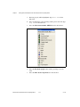
1.
Select Start»All Programs»Microsoft Visual Studio
.NET 2003»Microsoft Visual Studio .NET 2003.
2.
Select File»New»Project. The New Project dialog box launches.
Measurement Studio Measurement Computing Edition
3-2
ni.com
Chapter 3
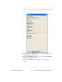
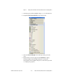
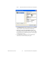
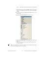
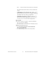
3.
4.
Getting Started with Measurement Studio Measurement Computing Edition
In the Project Types pane, expand the Measurement Studio Projects
folder. Select Visual Basic Projects or Visual C# Projects, depending
on which language you want to create the project in.
In the Templates pane, select Windows Application. Specify
MyMCCDAQProject for Name and specify a Location of your choice.
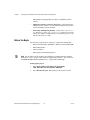
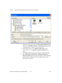
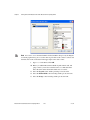
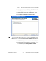
5.
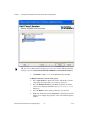
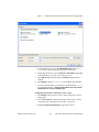
Click OK. The Measurement Studio Application Wizard launches.
6.
Select Universal Library and Windows Forms User Interface
Controls. When you select these libraries, the Measurement Studio
Application Wizard automatically adds references to the appropriate
class libraries.
© National Instruments Corporation
3-3
Measurement Studio Measurement Computing Edition
Chapter 3
Getting Started with Measurement Studio Measurement Computing Edition
Tip If you are working with an existing project, you can access the Add Class Libraries
dialog box by selecting Measurement Studio»Add/Remove Class Libraries Wizard.
7.
Click Finish to display Form1 in the Windows Forms Designer.
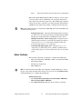
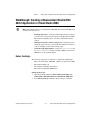
Adding user interface controls to the project
1.
Select View»Toolbox to display the Toolbox. The Toolbox contains
components and controls that you can add to your project.
2.
Select the Windows Forms tab. The Windows Forms tab contains
controls and components included in the System.Windows.Forms
namespace.
3.
Select the Button control and drag and drop it onto the form.
4.
Right-click the button and select Properties to display the Properties
window. You configure the properties of the control in the Properties
window.
Measurement Studio Measurement Computing Edition
3-4
ni.com
Chapter 3
Getting Started with Measurement Studio Measurement Computing Edition
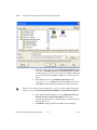
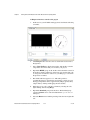
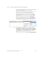
5.
The Text property will be highlighted. Type Start for the button text.
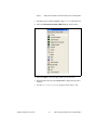
6.
Select the Measurement Studio .NET Tools tab on the Toolbox.
7.
Select the Meter control and drag and drop it onto the form.
8.
Right-click the meter and select Properties to display the Properties
window.
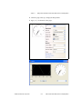
9.
Set the CoercionIntervalBase property for the meter to –10.
© National Instruments Corporation
3-5
Measurement Studio Measurement Computing Edition
Chapter 3
Getting Started with Measurement Studio Measurement Computing Edition
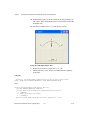
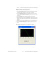
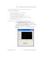
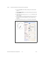
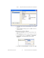
10. Set the Range property for the meter with the drop-down Range type
editor. Type –10 for the minimum value. Leave the default of 10 for the
maximum value.
The following screenshot shows Form1 with the user controls.
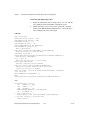
Generating and displaying the data
1.
Double-click on Form1 to display the Form1 code.
2.
Add the following code to declare a new Measurement Computing
board object.
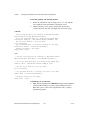
[VB.NET]
' Declare a new Measurement Computing board object that uses board 0
Public DaqBoard As MCCDaq.MCCBoard = New MCCDaq.MCCBoard(0)
[C#]
private System.Windows.Forms.Button button1;
private MCCDaq.MCCBoard daqBoard;
private NationalInstruments.UI.WindowsForms.Meter meter1;
/// <summary>
/// Required designer variable.
/// </summary>
private System.ComponentModel.Container components = null;
Measurement Studio Measurement Computing Edition
3-6
ni.com
Chapter 3
Getting Started with Measurement Studio Measurement Computing Edition
public Form1()
{
// Required for Windows Form Designer support
InitializeComponent();
daqBoard =new MCCDaq.MCCBoard(0);
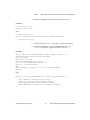
3.
Scroll down to move the cursor inside the click event handler of the
button control.
4.
Add the following code to read a raw data point from a specified
channel on the Measurement Computing device, convert the data to
volts, and display the value on the meter.
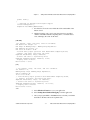
[VB.NET]
'Set channel, range, raw value, and volt variables.
Dim Channel As Integer = 0
Dim Range As MCCDaq.Range = MCCDaq.Range.Bip10Volts
Dim RawValue As Integer = 0
Dim Volts As Double = 0.0F
' Perform analog input operation with Measurement Computing board,
' channel, and range, and return raw value.
DaqBoard.AIn(Channel, Range, RawValue)
' Convert raw value to engineering units.
DaqBoard.ToEngUnits(Range, RawValue, Volts)
' Display value on meter.
Meter1.Value = Volts
[C#]
// Set channel, range, raw value, and volt variables.
int channel = 0;
MCCDaq.Range range =MCCDaq.Range.Bip10Volts;
ushort rawValue =0;
float volts =0.0f;
// Perform analog input operation with Measurement Computing board,
/// channel, and range, and return raw value.
daqBoard.AIn(channel, range, out rawValue);
// Convert raw value to engineering units.
daqBoard.ToEngUnits(range, rawValue, out volts);
// Display value on meter.
meter1.Value =volts;
2003
5.
Select File»Save Form1.cs to save your application.
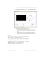
6.
Select Debug»Start Without Debugging to run the application.
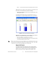
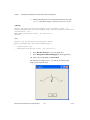
7.
After your program builds, click Start. Notice each time you click the
Start button, the meter shows the acquired value.
© National Instruments Corporation
3-7
Measurement Studio Measurement Computing Edition
Chapter 3
Getting Started with Measurement Studio Measurement Computing Edition
The following screenshot shows Form1 with the meter displaying the
acquired value.
Walkthrough: Creating a Measurement Studio MCC DAQ
Scan Components Application in Visual Studio 2003
Measurement Studio includes a component library and application
templates that you can use to quickly create MccDaq Components
applications with Visual Basic .NET and Visual C#. Refer to the following
section, Walkthrough: Creating a Measurement Studio MccDaq
Components Application, for step-by-step instructions on how to create a
Measurement Studio MccDaq Components project.
Measurement Studio Measurement Computing Edition
3-8
ni.com
Chapter 3
Getting Started with Measurement Studio Measurement Computing Edition
Measurement Studio MCC Edition includes user interface controls, such as
a waveform graph control, and MccDaq scan components that perform
analog input scans and analog output scans. This walkthrough is designed
to help you learn how to add analog scan and presentation functionality to
a Windows Forms application by taking you through the following steps:
Note This walkthrough refers to Visual Studio .NET 2003, but Visual Studio 2005 users
can follow the same process.
•
Setting up the project—Using the Visual Studio New Project dialog,
you will create a new project that references the Measurement Studio
MccDaq Scan Components library and Windows Forms controls.
•
Adding user interface controls to the project—Using the Toolbox
and the Properties window, you will add and configure user interface
controls and MccDaq.Scan components, including a button and
waveform graph, and an AiScan component.
•
Generating and displaying the data—Using the MccDaq.Scan
components, you will read data from a channel on an MCC device,
convert the data object to an array, and show the value on a waveform
graph.
Before You Begin
The following components are required to complete this walkthrough:
•
Microsoft Visual Studio .NET 2003 or Microsoft Visual Studio 2005
•
Measurement Studio
•
MccDaq Scan Components
•
MCC DAQ device
Note For information about installing and configuring your MCC DAQ device, refer to
the Quick Start Guide that ships with your device. You can also use the DEMO-BOARD
simulated DAQ device to complete this walkthrough.
Setting up the project
1.
Select Start»All Programs»Microsoft Visual Studio .NET 2003»
Microsoft Visual Studio .NET 2003.
2.
Select File»New»Project. The New Project dialog box launches.
© National Instruments Corporation
3-9
Measurement Studio Measurement Computing Edition
Chapter 3
Getting Started with Measurement Studio Measurement Computing Edition
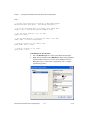
3.
4.
In the Project Types pane, expand the Measurement Studio Projects
folder. Select Visual Basic Projects or Visual C# Projects, depending
on which language you want to create the project in.
In the Templates pane, select Windows Application. Specify
MyMCCScanProject for Name and specify a Location of your
choice.
5.
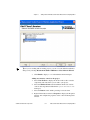
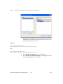
Click OK. The Measurement Studio Application Wizard launches.
6.
Select MccDaq Scan Components and Windows Forms User
Interface Controls. When you select these libraries, the Measurement
Studio Application Wizard automatically adds references to the
appropriate class libraries.
Measurement Studio Measurement Computing Edition
3-10
ni.com
Chapter 3
Getting Started with Measurement Studio Measurement Computing Edition
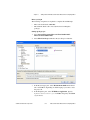
Tip If you are working with an existing project, you can access the Add Class Libraries
dialog box by selecting Measurement Studio»Add/Remove Class Libraries Wizard.
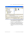
7.
Click Finish to display Form1 in the Windows Forms Designer.
Adding user interface controls to the project
1.
Select View»Toolbox to display the Toolbox. The toolbox contains
components and controls that you can add to your project.
2.
Select the Windows Forms tab. The Windows Forms tab contains
controls and components included in the System.Windows.Forms
namespace.
3.
Select the Button control and drag and drop it onto the form.
4.
Right-click the button and select Properties to display the Properties
window. You configure the properties of the control in the Properties
window.
© National Instruments Corporation
3-11
Measurement Studio Measurement Computing Edition
Chapter 3
Getting Started with Measurement Studio Measurement Computing Edition
5.
The Text property will be highlighted. Type Start Scan for the
button text.
6.
Select another button control and drag and drop it onto the form. Type
Stop Scan for the button text.
7.
Select the Measurement Studio .NET Tools tab on the Toolbox.
8.
Select the Waveform graph control and drag and drop it onto the
form.
9.
Select the MCC Scan Components tab on the Toolbox.
Measurement Studio Measurement Computing Edition
3-12
ni.com
Chapter 3
Getting Started with Measurement Studio Measurement Computing Edition
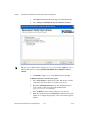
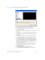
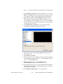
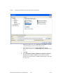
10. Double-click on the AIScan component (aiScan1) to add it to the
component tray beneath the form.
11. Right-click the AIScan component (aiScan1) and select Properties
to display the Properties window.
12. Click on the ClockRate property and type 500 for this property
setting.
© National Instruments Corporation
3-13
Measurement Studio Measurement Computing Edition
Chapter 3
Getting Started with Measurement Studio Measurement Computing Edition
The following screenshot shows Form1 with the user controls. The AIScan
component is shown in the component tray.
Generating and displaying the data
1.
Double-click on the Start Scan button to display the Form1 code.
2.
Add the following line of code to start an analog in scan.
[VB.NET]
' This starts the scan
AiScan1.Operate()
[C#]
// This starts the scan
private void button1_Click(object sender, System.EventArgs e)
{
aiScan1.Operate();
}
3.
Double-click on the Stop Scan button to open the code window.
Measurement Studio Measurement Computing Edition
3-14
ni.com
Chapter 3
4.
Getting Started with Measurement Studio Measurement Computing Edition
Add the following line of code that stops the analog in scan.
[VB.NET]
' This stops the scan
AiScan1.Break = True
[C#]
// This stops the scan
private void button2_Click(object sender, System.EventArgs e)
{
aiScan1.Break =true;
}
5.
6.
Double-click on the AIScan component to open the code window.
Add the following lines of code to the DataReady event of the
aiScan1 component to copy the analog data to an array.
[VB.NET]
Private Sub AiScan1_DataReady(ByVal sender As Object, ByVal e As
System.EventArgs) Handles AiScan1.DataReady
Dim I As Integer
Dim yData() As Double
ReDim yData(UBound(AiScan1.Values) - 1)
For I = 0 To UBound(AiScan1.Values) - 1
yData(I) = AiScan1.Values(I)
Next
WaveformGraph1.PlotY(yData, 0, 1.0 / AiScan1.ActualRate)
End Sub
[C#]
private void aiScan1_DataReady(object sender, System.EventArgs e)
{
Array tempArray =aiScan1.Values as Array;
double[] yData =new double[tempArray.Length];
Array.Copy(tempArray, yData, tempArray.Length);
waveformGraph1.PlotY(yData, 0, 1.0/aiScan1.ActualRate);
}
© National Instruments Corporation
3-15
Measurement Studio Measurement Computing Edition
Chapter 3
Getting Started with Measurement Studio Measurement Computing Edition
7.
Add the following lines of code to the ErrorOccurred event of the
aiScan1 component to display a message box if an error occurs.
[VB.NET]
Private Sub AiScan1_ErrorOccurred(ByVal sender As Object, ByVal e As
MccDaq.ScanComponents.ErrorOccurredEventArgs) Handles AiScan1.ErrorOccurred
AiScan1.Break = True
MessageBox.Show(AiScan1.Status, "AI Scan Error")
End Sub
[C#]
private void aiScan1_ErrorOccurred(object sender,
MccDaq.ScanComponents.ErrorOccurredEventArgs e)
{
aiScan1.Break =true;
MessageBox.Show(aiScan1.Status, "AI Scan Error");
}
8.
Select File»Save Form1.cs to save your application.
9.
Select Debug»Start Without Debugging to run the application.
10. After your program builds, click Start Scan.
The following screenshot shows Form1 with the waveform graph
displaying the acquired values.
Measurement Studio Measurement Computing Edition
3-16
ni.com
Chapter 3
Getting Started with Measurement Studio Measurement Computing Edition
Walkthrough: Creating a Measurement Studio MCC
488.2 Application in Visual Studio 2003
Note This walkthrough refers to Visual Studio .NET 2003, but Visual Studio 2005 users
can follow the same process.
•
Setting up the project—Using the Visual Studio New Project dialog,
you will create a new project that references the Measurement Studio
Measurement Computing 488.2 class library and Windows Forms
controls.
•
Adding user interface controls to the project—Using the Toolbox
and the Properties window, you will add and configure user interface
controls, including a button and waveform graph.
•
Generating and displaying data—Using MCC.488.2.Device and
MCC.488.2.Address, you will read and plot 100 data points from a
GPIB device at the specified address.
Before You Begin
The following components are required to complete this walkthrough:
•
Microsoft Visual Studio .NET 2003 or Microsoft Visual Studio 2005
•
Measurement Studio 8.0
•
Measurement Computing 488.2 Library
•
Measurement Computing GPIB Device
Setting up the project
1.
Open Visual Studio .NET from Start»All Programs»Microsoft
Visual Studio .NET 2003»Microsoft Visual Studio .NET 2003.
2.
Select File»New»Project. The New Project dialog box launches.
© National Instruments Corporation
3-17
Measurement Studio Measurement Computing Edition
Chapter 3
Getting Started with Measurement Studio Measurement Computing Edition
3.
4.
In the Project Types pane, expand the Measurement Studio Projects
folder. Select Visual Basic Projects or Visual C# Projects, depending
on which language you want to create the project in. This walkthrough
refers to Visual C#, but Visual Basic .NET users can follow the same
process.
In the Templates pane, select Windows Application. Specify
MyMCCGPIBProject for Name and select a Location of your choice.
5.
Click OK. The Measurement Studio Application Wizard launches.
Tip If you are working with an existing project, you can access the Add Class Libraries
dialog box by selecting Measurement Studio»Add/Remove Class Libraries Wizard.
6.
In the Application Wizard dialog box, select Windows Forms User
Interface Controls and MCC 488.2 Library. The wizard
automatically adds references to the appropriate class libraries and sets
up the project for you.
7.
Click Finish to display Form1 in the Windows Forms Designer.
Measurement Studio Measurement Computing Edition
3-18
ni.com
Chapter 3
Getting Started with Measurement Studio Measurement Computing Edition
Adding user interface controls to the project
1.
Select View»Toolbox to display the Toolbox. The Toolbox contains
components and controls that you can add to your project.
2.
Select the Windows Forms tab. The Windows Forms tab contains
controls and components included in the System.Windows.Forms
namespace.
3.
Select the Button control and drag and drop it onto the form.
4.
Right-click the button and select Properties to display the Properties
window. You configure the properties of the control in the Properties
window.
5.
The Text property will be highlighted. Type Run for the button text.
6.
Select the WaveformGraph control and drag and drop it onto the
form.
The following screenshot shows Form1 with the user controls.
© National Instruments Corporation
3-19
Measurement Studio Measurement Computing Edition
Chapter 3
Getting Started with Measurement Studio Measurement Computing Edition
Generating and displaying the data
1.
Double-click the button control to display the Form1 code, with the
cursor inside the click event handler of the button control.
2.
Add the following code to read a raw data point from a specified
channel on the Measurement Computing device, convert the data to
volts, and display the value on the graph.
[VB.NET]
Dim I As Integer
Dim WrtString As String = "val?"
Dim RdBufSize As Integer = 100
Dim NlChar As Char = "\n"
Dim NullChar As Char = "\0"
Dim PrimaryAddress As New Address(2)
Dim BoardNum As Integer = 0
' Open a gpib device
Dim Device As New Device(BoardNum, PrimaryAddress)
' Allocate a buffer to hold the data
Dim Buffer As IntPtr =
System.Runtime.InteropServices.Marshal.AllocHGlobal(RdBufSize)
' Read and plot 100 samples
For I = 0 To 99
' Write the string (val?) to the Fluke45
Device.Write(WrtString)
' Read the response from the Fluke45
Dim S As String = Device.ReadString(RdBufSize)
' Replace the newline character with a null and
' convert the string to a double
Dim D As Double = Convert.ToDouble(S.Replace(NlChar, NullChar))
'Plot the point
WaveformGraph1.PlotYAppend(D, 1)
Next
System.Runtime.InteropServices.Marshal.FreeHGlobal(Buffer)
[C#]
stringwrtString = "val?";
int
rdBufSize = 100;
char
nlChar = '\n';
char
nullChar = '\0';
addressprimaryAddress = new Address(2);
int
boardNum = 0;
// open a gpib device
Device device = new Device(boardNum, primaryAddress);
// allocate a buffer to hold the data
IntPtr buffer =
Measurement Studio Measurement Computing Edition
3-20
ni.com
Chapter 3
Getting Started with Measurement Studio Measurement Computing Edition
System.Runtime.InteropServices.Marshal.AllocHGlobal(rdBufSize);
// read and plot 100 samples
for (int i=0; i<100; i++)
{
// write the string (val?) to the Fluke45
device.Write(wrtString);
// read the response from the Fluke45
string s = device.ReadString(rdBufSize);
// replace the newline character with a null and
// convert the string to a double
double d = Convert.ToDouble(s.Replace(nlChar, nullChar));
// plot the point
waveformGraph1.PlotYAppend(d, 1);
}
System.Runtime.InteropServices.Marshal.FreeHGlobal(buffer);
3.
Select File»Save Form1.cs to save your application.
4.
Select Debug»Start Without Debugging to run the application.
5.
After your program builds, click Run. Notice each time you click the
Run button, the graph shows the acquired value.
The following screenshot shows Form1 with the graph displaying the
acquired value.
© National Instruments Corporation
3-21
Measurement Studio Measurement Computing Edition
Chapter 3
Getting Started with Measurement Studio Measurement Computing Edition
Measurement Studio Walkthroughs for Visual
Studio 2005
Use the following walkthroughs to help you develop Measurement Studio
applications in Visual Studio 2005:
•
Walkthrough: Creating a Measurement Studio Application with
Windows Forms Controls and Analysis in Visual Studio 2005
•
Walkthrough: Creating a Measurement Studio Application with Web
Forms Controls and Analysis in Visual Studio 2005
•
Creating a Measurement Studio Application with Web Forms Controls
and Network Variable in Visual Studio 2005
Walkthrough: Creating a Measurement Studio
Application with Windows Forms Controls and Analysis
in Visual Studio 2005
Measurement Studio includes user interface controls, such as a waveform
graph control and a gauge control, and analysis functionality, such as signal
generation and mathematical functions. This walkthrough is designed to
help you learn how to add analysis and presentation functionality to a
Windows Forms application by taking you through the following steps:
•
Setting up the project—Using the Measurement Studio Application
Wizard, you will create a new project that references the Measurement
Studio Analysis class library and Windows Forms controls.
•
Adding user interface controls to the project—Using the Toolbox,
smart tags, and the Properties window, you will add and configure a
button, waveform graph, legend, gauge, and numeric edit user
interface control.
•
Generating, plotting, and analyzing the data—Using
NationalInstruments.Analysis.SignalGeneration.White
NoiseSignal and NationalInstruments.Analysis.Math.
Statistics.Mean, you will generate data, plot the generated data on
a waveform graph, and calculate the mean of the data.
•
Customizing the user interface—Using smart tags and the Collection
Editor and Auto Format dialog boxes, you will display the mean value
on the gauge and the numeric edit, as well as customize your user
interface.
Measurement Studio Measurement Computing Edition
3-22
ni.com
Chapter 3
Getting Started with Measurement Studio Measurement Computing Edition
Before you begin
The following components are required to complete this walkthrough:
•
Microsoft Visual Studio .NET 2005
•
Measurement Studio 8.0.1 or later (Professional or Enterprise
package)
Setting up the project
1.
Select Start»All Programs»Microsoft Visual Studio 2005»
Microsoft Visual Studio 2005.
2.
Select File»New»Project. The New Project dialog box launches.
3.
In the Project Types pane, select Measurement Studio under Visual
C# or Visual Basic, depending on which language you want to create
the project in.
4.
In the Templates pane, select NI Windows Application. Specify
MyMeasurementStudioProject for Name and specify a Location
of your choice.
© National Instruments Corporation
3-23
Measurement Studio Measurement Computing Edition
Chapter 3
Getting Started with Measurement Studio Measurement Computing Edition
5.
Click OK. The Measurement Studio Application Wizard launches.
6.
Select Analysis and Windows Forms User Interface Controls.
Tip If you are working with an existing project, you can access the Add/Remove Class
Libraries dialog box by selecting Measurement Studio»View .NET Class Library
Wizard.
7.
Click Finish to display Form1 in the Windows Forms Designer.
Adding user interface controls to the project
1.
Select View»Toolbox to display the Toolbox. The Toolbox contains
components and controls that you can add to your project.
2.
Expand the All Windows Forms group. The All Windows Forms
group contains controls and components included in the
System.WindowsForms namespace.
3.
Select the Button control and drag and drop it onto the form.
4.
Right-click the button and select Properties to display the Properties
window. You configure the properties of the control in the Properties
window.
Measurement Studio Measurement Computing Edition
3-24
ni.com
Chapter 3
Getting Started with Measurement Studio Measurement Computing Edition
5.
The Text property will be highlighted. Type Start for the button text.
6.
Expand the Measurement Studio group in the Toolbox.
7.
Select the WaveformGraph control and drag and drop it onto the
form.
8.
Right-click the waveform graph and select Edit Plots to display
the WaveformPlot Collection Editor dialog box. You use the
WaveformPlot Collection Editor dialog box to add or remove plots and
to configure plot properties.
© National Instruments Corporation
3-25
Measurement Studio Measurement Computing Edition
Chapter 3
Getting Started with Measurement Studio Measurement Computing Edition
Note You can also access the WaveformPlot Collection Editor dialog box by clicking the
waveform graph smart tag. To access the smart tag, left click on the control to select it and
then left click on the arrow button in the upper right corner of the control.
9.
Type Plot for the Name. Click OK.
10. Before you add the Measurement Studio legend, numeric edit, and
gauge controls, you need to resize the form to accommodate them.
Select the form and use the double-sided arrow to resize it.
11. Select the Legend control and drag and drop it onto the form.
12. Select the NumericEdit control and drag and drop it onto the form.
13. Select the Gauge control and drag and drop it onto the form.
Measurement Studio Measurement Computing Edition
3-26
ni.com
Chapter 3
Getting Started with Measurement Studio Measurement Computing Edition
14. Click the gauge smart tag to display the Gauge Tasks.
15. Type gauge for the name of the gauge.
© National Instruments Corporation
3-27
Measurement Studio Measurement Computing Edition
Chapter 3
Getting Started with Measurement Studio Measurement Computing Edition
Generating, plotting, and analyzing the data
1.
Double-click the button control to display the Form1 code, with the
cursor inside the click event handler of the button control.
2.
Add the following code to generate random data, plot the data,
calculate the mean of the data, and display the mean on the gauge.
[VB.NET]
' Declare and initialize an instance of WhiteNoiseSignal.
Dim whiteNoise As New WhiteNoiseSignal()
' Store the generated data in a double array named data.
Dim data As Double() = whiteNoise.Generate(1000.0, 256)
' Use the PlotY method to plot the data.
Plot.PlotY(data)
' Use the Mean method to calculate the mean of the data.
Dim mean As Double = Statistics.Mean(data)
' Display the mean on the gauge.
gauge.Value = mean
[C#]
// Declare and initialize an instance of WhiteNoiseSignal.
WhiteNoiseSignal whiteNoise = new WhiteNoiseSignal();
// Store the generated data in a double array named data.
double[] data = whiteNoise.Generate(1000.0, 256);
// Use the PlotY method to plot the data.
Plot.PlotY(data);
// Use the Mean method to calculate the mean of the data.
double mean = Statistics.Mean(data);
// Display the mean on the gauge.
gauge.Value = mean;
Customizing your user interface
1.
Right-click the legend and select Edit Items to display the LegendItem
Collection Editor dialog box. You use the LegendItem Collection
Editor dialog box to add or remove legend items and to configure
legend item properties.
Measurement Studio Measurement Computing Edition
3-28
ni.com
Chapter 3
Getting Started with Measurement Studio Measurement Computing Edition
2.
Select Plot in the Source drop-down list and enter Signal in the Text
box. Click OK. Now that you have specified a legend item for the plot,
changes you make to the plot will be reflected on the legend.
3.
Right-click the graph and select Auto Format to display the Auto
Format dialog box. The Auto Format dialog box provides a set of
pre-configured control styles. When you select a style and click OK,
the Auto Format feature configures the appropriate control properties
to reflect the style you chose.
4.
Select Points Only. Click OK. Notice that the legend changed
automatically to match the formatting of the graph.
© National Instruments Corporation
3-29
Measurement Studio Measurement Computing Edition
Chapter 3
Getting Started with Measurement Studio Measurement Computing Edition
5.
Click the gauge smart tag to display the Gauge Tasks.
6.
Select Auto Format to display the Auto Format dialog box.
7.
Select Dark and click OK.
8.
Right-click the gauge and select Properties to display the Properties
window.
9.
Set the Range property for the gauge with the drop-down Range type
editor. Type -0.2 for the minimum value and type 0.2 for the
maximum value.
10. Click the numeric edit smart tag to display the Numeric Edit Tasks.
11. Select Gauge in the Source drop-down list. Setting the Source
property to the gauge allows two-way binding between the controls.
12. Deselect ArrowKeys, Buttons, and Text for the InteractionMode
property of the numeric edit control. Deselecting these interaction
modes makes the numeric edit an indicator. The numeric edit control
only displays the calculated mean.
13. Select the Format Mode property and in the Numeric Edit Format
Mode Editor dialog box, change the Precision to 4 to show four
decimal places of precision.
14. Select File»Save Form1.cs to save your application.
15. Select Debug»Start Without Debugging to run the application.
Measurement Studio Measurement Computing Edition
3-30
ni.com
Chapter 3
Getting Started with Measurement Studio Measurement Computing Edition
16. After your program builds, click Start. Notice the graph shows the
data plot, and the gauge and the numeric edit display the mean of the
data.
The following screenshot shows Form1 with customization.
Walkthrough: Creating a Measurement Studio
Application with Web Forms Controls and Analysis in
Visual Studio 2005
Measurement Studio includes user interface controls, such as a waveform
graph control and a gauge control, and Analysis functionality, such as
signal generation and mathematical functions. This walkthrough is
designed to help you learn how to add analysis and presentation
functionality to a Web Forms application by taking you through the
following steps:
•
Setting up the project—Using the Measurement Studio Application
Wizard, you will create a new project that references the Measurement
Studio Analysis class library and Web Forms controls.
•
Adding user interface controls to the project—Using the Toolbox
and the Properties window, you will add and configure a button,
waveform graph, legend, gauge, and numeric edit user interface
control.
•
Generating, plotting, and analyzing the data—Using
NationalInstruments.Analysis.SignalGeneration.White
NoiseSignal and NationalInstruments.Analysis.Math.
© National Instruments Corporation
3-31
Measurement Studio Measurement Computing Edition
Chapter 3
Getting Started with Measurement Studio Measurement Computing Edition
Statistics.Mean, you will generate data, plot the generated data on
a waveform graph, and calculate the mean of the data.
•
Customizing the user interface—Using the Collection Editor and
Auto Format dialog boxes, you will display the mean value on the
gauge and the numeric edit, as well as customize your user interface.
Before you begin
The following components are required to complete this walkthrough:
•
Microsoft Visual Studio .NET 2005
•
Measurement Studio 8.0.1 or later (Professional or Enterprise
package)
Setting up the project
1.
Select Start»All Programs»Microsoft Visual Studio 2005»
Microsoft Visual Studio 2005.
2.
Select File»New»Web Site. The New Web Site dialog box launches.
3.
In the Templates pane, select NI ASP.NET Web Site. Select File
System and specify a file path of your choice.
Measurement Studio Measurement Computing Edition
3-32
ni.com
Chapter 3
Getting Started with Measurement Studio Measurement Computing Edition
4.
Use the drop-down box to select Visual C# or Visual Basic, depending
on which language you want to create the project in.
5.
Click OK. The Measurement Studio ASP.NET Web Site Wizard
launches.
6.
Select Analysis and Web Forms User Interface Controls.
Tip If you are working with an existing project, you can access the Add/Remove Class
Libraries dialog box by selecting Measurement Studio»Add/Remove Class Libraries
Wizard.
7.
Click Finish to display Default.aspx in the Web Forms Designer.
8.
You can change the title of your Web page. Click inside the <title>
tag and rename the title to Measurement Studio Web Forms
Controls and Analysis Walkthrough.
© National Instruments Corporation
3-33
Measurement Studio Measurement Computing Edition
Chapter 3
Getting Started with Measurement Studio Measurement Computing Edition
Adding user interface controls to the project
1.
In this section, you will build a Web page that looks like the following
screenshot.
2.
Click Design in the lower left corner to switch from Source View to
Design View.
3.
Select View»Toolbox to display the Toolbox. The Toolbox contains
components and controls that you can add to your project.
4.
Expand the HTML group on the Toolbox. Select the Table control in
the Toolbox and drag and drop it on the form. You use the table cells
to arrange the user interface controls on your Web page, as shown in
the previous screenshot.
5.
The default table that appears is 3×3. This table provides a
customizable form for arranging the user interface controls for your
Web page. Expand the table to approximately 300 px (pixels) tall by
550 px wide by clicking and dragging the table borders.
6.
Merge the top two cells of all three columns by selecting the cells,
right-clicking, and selecting Merge.
7.
Expand the Standard group on the Toolbox. The Standard group
contains ASP.NET server controls included in the System.Web.UI
namespace.
8.
Select the Button control and drag and drop it into the lower right table
cell.
Measurement Studio Measurement Computing Edition
3-34
ni.com
Chapter 3
9.
Getting Started with Measurement Studio Measurement Computing Edition
Right-click the button and select Properties to display the Properties
window. You configure the properties of the control in the Properties
window.
10. Scroll to the Text property in the Properties window. Type Start for
the button text.
11. Expand the Measurement Studio group on the Toolbox.
12. Select the WaveformGraph control and drag and drop it into the top
table cell.
13. On the waveform graph smart tag, type graph for the name of the
waveform graph ID.
Tip To access the smart tag, left click on a control to select it and then left click on the
arrow button in the upper right corner of the control.
© National Instruments Corporation
3-35
Measurement Studio Measurement Computing Edition
Chapter 3
Getting Started with Measurement Studio Measurement Computing Edition
14. Select the Legend control and drag and drop it into the bottom left
table cell.
15. Select the NumericEdit control and drag and drop it into the bottom
center table cell.
16. On the numeric edit smart tag, type numericedit for the name of the
numeric edit ID.
17. Select the Gauge control and drag and drop it into the top table cell, to
the right of the waveform graph. Resize controls and table cells as
necessary.
18. On the gauge smart tag, type gauge for the name of the gauge ID.
Measurement Studio Measurement Computing Edition
3-36
ni.com
Chapter 3
Getting Started with Measurement Studio Measurement Computing Edition
The following screenshot shows Default.aspx with the user controls.
Generating, plotting, and analyzing the data
1.
Double-click the button control to display the Default.aspx.cs
code, with the cursor inside the click event handler of the button
control.
2.
Add the following code to generate random data, plot the data,
calculate the mean of the data, and display the mean on the gauge.
[VB.NET]
' Declare and initialize an instance of WhiteNoiseSignal.
Dim whiteNoise As New WhiteNoiseSignal()
' Store the generated data in a double array named data.
Dim data As Double() = whiteNoise.Generate(1000.0, 256)
' Use the PlotY method to plot the data.
graph.PlotY(data)
' Use the Mean method to calculate the mean of the data.
Dim mean As Double = Statistics.Mean(data)
' Display the mean on the numeric edit.
numericedit.Value = mean
' Display the mean on the gauge.
gauge.Value = mean
© National Instruments Corporation
3-37
Measurement Studio Measurement Computing Edition
Chapter 3
Getting Started with Measurement Studio Measurement Computing Edition
[C#]
// Declare and initialize an instance of WhiteNoiseSignal.
WhiteNoiseSignal whiteNoise = new WhiteNoiseSignal();
// Store the generated data in a double array named data.
double[] data = whiteNoise.Generate(1000.0, 256);
// Use the PlotY method to plot the data.
graph.PlotY(data);
// Use the Mean method to calculate the mean of the data.
double mean = Statistics.Mean(data);
// Display the mean on the numeric edit.
numericedit.Value = mean;
// Display the mean on the gauge.
gauge.Value = mean;
Customizing your user interface
1.
Select the Default.aspx tab to return to the Web Forms Designer.
2.
Right-click the legend and select Edit Items to display the LegendItem
Collection Editor dialog box. You use the LegendItem Collection
Editor dialog box to add or remove legend items and to configure
legend item properties.
Measurement Studio Measurement Computing Edition
3-38
ni.com
Chapter 3
Getting Started with Measurement Studio Measurement Computing Edition
3.
Select Plots[0] in the Source drop-down list and enter Signal in the
Text box. Click OK. Now that you have specified a legend item for the
plot, changes you make to the plot will be reflected on the legend.
4.
Right-click the graph and select Auto Format to display the Auto
Format dialog box. The Auto Format dialog box provides a set of
pre-configured control styles. When you select a style and click OK,
the Auto Format feature configures the appropriate control properties
to reflect the style you chose.
5.
Select Points Only. Click OK. Notice that the legend changed
automatically to match the formatting of the graph.
6.
Right-click the gauge and select Auto Format to display the Auto
Format dialog box.
7.
Select Dark and click OK.
8.
On the gauge smart tag, set the Range property for the gauge with the
drop-down Range type editor. Type -0.2 for the minimum value and
type 0.2 for the maximum value.
9.
On the numeric edit smart tag, select Indicator for the
InteractionMode property of the numeric edit control.
10. On the numeric edit smart tag, select Format Mode and in the Numeric
Format Mode Editor dialog box, change the Precision to 4 to show four
decimal places of precision.
11. Select File»Save Default.aspx to save your application.
© National Instruments Corporation
3-39
Measurement Studio Measurement Computing Edition
Chapter 3
Getting Started with Measurement Studio Measurement Computing Edition
12. Select Debug»Start Without Debugging to run the application.
13. After your program builds, click Start. Notice the graph shows the
data plot, and the gauge and the numeric edit display the mean of the
data. The following screenshot shows Default.aspx in its final
form.
Creating a Measurement Studio Application with
Web Forms Controls and Network Variable in Visual
Studio 2005
Measurement Studio includes user interface controls, such as a waveform
graph control, and network variable functionality to transfer live
measurement data between applications over the network. This
walkthrough is designed to help you learn how to add network variable
functionality to a Web Forms application by taking you through the
following steps:
•
Writing an array of data to the server—Using
NationalInstruments.NetworkVariable.NetworkVariable
BufferedWriter<TValue>, you will create and run a console
application that writes an array of values to the server.
•
Setting up a Web Forms project—Using the Measurement Studio
Application Wizard, you will create a new project that references the
Measurement Studio Measurement Computing Edition
3-40
ni.com
Chapter 3
Getting Started with Measurement Studio Measurement Computing Edition
Measurement Studio Network Variable class library and Web Forms
controls.
•
Configuring the network variable data source control—Using the
Toolbox and the NationalInstruments.NetworkVariable.
WebForms.NetworkVariableDataSource smart tag, you will add
and configure a data source control to your application.
•
Displaying the array of data on a Web page—Using the Toolbox,
you will add and configure an NationalInstruments.UI.
WebForms.AutoRefresh control and a NationalInstruments.
UI.WebForms.WaveformGraph control to display the data.
Before you begin
The following components are required to complete this walkthrough:
•
Microsoft Visual Studio .NET 2005
•
Measurement Studio 8.1 or later (Professional or Enterprise package)
Writing an array of data to the server
1.
Select Start»All Programs»Microsoft Visual Studio 2005»
Microsoft Visual Studio 2005.
2.
Select File»New»Project. The New Project dialog launches.
© National Instruments Corporation
3-41
Measurement Studio Measurement Computing Edition
Chapter 3
Getting Started with Measurement Studio Measurement Computing Edition
3.
4.
In the Project Types pane, select Visual C# or Visual Basic, depending
on which language you want to create the project in.
In the Templates pane, select Console Application. Specify
NetworkVariableWriter for Name and specify a Location of your
choice.
5.
Click OK.
6.
Select Measurement Studio»Add/Remove .NET Class Libraries.
The Measurement Studio Add/Remove Class Libraries Wizard
launches. You use this wizard to add Measurement Studio components
to your project.
Measurement Studio Measurement Computing Edition
3-42
ni.com
Chapter 3
7.
Getting Started with Measurement Studio Measurement Computing Edition
In Program.cs, add the following code to write an array of data to the
server:
[VB.NET]
Imports NationalInstruments.NetworkVariable
Imports System.Threading
Module Module1
Private Function GenerateDoubleArray(ByVal phase As Double) As Double()
Dim values(999) As Double
Dim x As Integer
For x = 0 To 999
values(x) = Math.Sin(((2 * Math.PI * x) / 1000) + phase) * 2
Next x
Return values
End Function
Sub Main()
Const location As String = "\\localhost\system\double"
Dim bufferedWriter As NetworkVariableBufferedWriter(Of Double()) =
New NetworkVariableBufferedWriter(Of Double())(location)
bufferedWriter.Connect()
Dim phase As Integer = 0
While (True)
Dim values As Double() = GenerateDoubleArray(phase)
Console.WriteLine("Writing Array")
bufferedWriter.WriteValue(values)
Thread.Sleep(500)
phase = phase + 1
End While
End Sub
End Module
[C#]
using System;
using System.Threading;
using NationalInstruments.NetworkVariable;
namespace NetworkVariableWriter
{
class Program
{
private static double[] GenerateDoubleArray(double phase)
{
double[] values = new double[1000];
for (int x = 0; x < 1000; x++)
values[x] = Math.Sin(((2 * Math.PI * x) / 1000) + phase) * 2;
return values;
}
© National Instruments Corporation
3-43
Measurement Studio Measurement Computing Edition
Chapter 3
Getting Started with Measurement Studio Measurement Computing Edition
static void Main(string[] args)
{
const string Location = @"\\localhost\system\double";
NetworkVariableBufferedWriter<double[]> bufferedWriter = new
NetworkVariableBufferedWriter<double[]>(Location);
bufferedWriter.Connect();
int phase = 0;
while (true)
{
double[] value = GenerateDoubleArray(phase);
Console.WriteLine("Writing array");
bufferedWriter.WriteValue(value);
Thread.Sleep(500);
phase++;
}
}
}
}
8.
Select Debug»Start Without Debugging to run the application.
9.
Minimize the console application, but keep the application running.
Setting up the Web Forms project
1.
Select Start»All Programs»Microsoft Visual Studio 2005»
Microsoft Visual Studio 2005.
2.
Select File»New»Web Site. The New Web Site dialog box launches.
Measurement Studio Measurement Computing Edition
3-44
ni.com
Chapter 3
3.
Getting Started with Measurement Studio Measurement Computing Edition
In the Templates pane, select NI ASP.NET Web Site. Select File
System for Location and specify a file path of your choice.
4.
Use the drop-down box to select Visual C# or Visual Basic, depending
on which language you want to create the project in.
5.
Click OK. The Measurement Studio ASP.NET Web Site Wizard
launches.
6.
Click Finish to display Default.aspx in the Web Forms Designer.
7.
You can rename the title of your Web page. Click inside the <title>
tag and rename the title to Measurement Studio Network Variable
and Web Forms Controls Walkthrough.
Configuring the network variable data source control
1.
Click Design in the lower left corner to switch from Source View to
Design View.
2.
Select View»Toolbox to display the Toolbox. The toolbox contains
components and controls that you can add to your project.
3.
Expand the Measurement Studio group on the Toolbox.
© National Instruments Corporation
3-45
Measurement Studio Measurement Computing Edition
Chapter 3
Getting Started with Measurement Studio Measurement Computing Edition
4.
Select the NetworkVariableDataSource control in the toolbox and drag
and drop it on the form. The NationalInstruments.
NetworkVariable.WebForms.NetworkVariableDataSource
control is a data source control with functionality similar to
System.Web.UI.WebControls.ObjectDataSource and
System.Web.UI.WebControls.SqlDataSourcein the .NET
Framework. The NationalInstruments.NetworkVariable.
WebForms.NetworkVariableDataSource control encapsulates
NationalInstruments.NetworkVariable functionality.
5.
In the NetworkVariableDataSource smart tag, select Edit Bindings to
launch the NetworkVariableBinding Collection Editor dialog box.
6.
Select Add. You add a binding to create a connection with the
underlying network variable, and you use the NetworkVariableBinding
Collection Editor to configure the binding properties. Select Object
for the BindingType. You select Object because this walkthrough
binds to NationalInstruments.UI.WebForms.
WaveformGraph.BindingData. Enter 0 as the DefaultReadValue.
Measurement Studio Measurement Computing Edition
3-46
ni.com
Chapter 3
Getting Started with Measurement Studio Measurement Computing Edition
7.
Click OK to return to the NetworkVariableBinding Collection Editor
dialog box.
8.
After you configure the binding properties, click OK to return to the
ASP.NET Designer.
Displaying the array of data on a Web page
1.
Select WaveformGraph in the Toolbox and drag and drop it on the
form.
2.
Select AutoRefresh in the Toolbox and drag and drop it on the form.
3.
In the AutoRefresh smart tag, check Enabled. Select Edit Default
Refresh Items to launch the RefreshItem Collection Editor
dialog box.
4.
Select Add. Select WaveformGraph1 for the ItemID and click OK.
© National Instruments Corporation
3-47
Measurement Studio Measurement Computing Edition
Chapter 3
Getting Started with Measurement Studio Measurement Computing Edition
5.
Double-click the AutoRefresh control. Add the following code to the
AutoRefresh event handler to bind the waveform graph control to the
network variable data source control:
[VB.NET]
WaveformGraph1.BindingData =
NetworkVariableDataSource1.Bindings(0).GetValue()
[C#]
WaveformGraph1.BindingData =
NetworkVariableDataSource1.Bindings[0].GetValue();
6.
Select File»Save Default.aspx to save your application.
7.
Select Debug»Start Without Debugging to run the application. The
waveform graph displays the array of data.
Measurement Studio Measurement Computing Edition
3-48
ni.com
Chapter 3
© National Instruments Corporation
Getting Started with Measurement Studio Measurement Computing Edition
3-49
Measurement Studio Measurement Computing Edition
Contacting Measurement
Computing Corp.
A
You can reach Measurement Computing Corp. through the following ways:
Mail
Measurement Computing Corp.
16 Commerce Blvd.
Middleboro, MA 02346
Telephone
508-946-5100
FAX
508-946-9500
Technical Support
[email protected]
Sales
[email protected]
Other correspondence
[email protected]
Visit our Web site at www.measurementcomputing.com.
© National Instruments Corporation
A-1
Measurement Studio Measurement Computing Edition
Glossary
A
analog I/O
Reading or writing data in continuously variable physical quantities, such
as voltage or current.
annotate
Adding text, arrows, or shapes to describe or highlight a point or region on
a graph.
API
Application Programming Interface. A specification of software functions
and their input and return parameters.
array control
An array of Measurement Studio user interface controls that behave as a
single unit.
assembly
A collection of one or more files that are versioned and deployed as a unit.
An assembly is the primary building block of a .NET Framework
application. All managed types and resources are contained within an
assembly and are marked either as accessible only within the assembly or
as accessible from code in other assemblies.
asynchronous
Function that begins an operation and returns control to the program prior
to the completion or termination of the operation.
B
button
A control used to input or display Boolean information or to initiate an
action in a program.
C
chart
To append new data points to the end of an existing plot over time.
client callback
In Web Forms, page calls back to the server without fully posting back.
Callbacks are asynchronous and are accomplished with XML-HTTP.
Client callbacks do not include postback data, and they do not force the
page to refresh. Client callbacks do require a browser that supports the
XML-HTTP protocol.
© National Instruments Corporation
G-1
Measurement Studio Measurement Computing Edition
Glossary
coercion
Automatic conversion that Measurement Studio controls perform to change
the numeric representation of a data element.
complex graph
A control that displays a ComplexDouble data type; the ComplexDouble
data type represents a complex number of type Double that is composed of
a real part and an imaginary part.
context-sensitive help
Help for dialog boxes, the controls in dialog boxes, and keywords in source
code that you can access with the key or a Help button, or by clicking the
link that appears in the Dynamic Help window in Visual Studio.
control
Object for entering, displaying, or manipulating data on a user interface.
counter/timer I/O
Reading or writing data based on high-precision timing through a counter
or timer. By combining a counter with a highly accurate clock, you can
create a wide variety of timing and counting applications, such as
monitoring and analyzing digital waveforms and generating complex
square waves.
cursor
Flashing rectangle that shows where you may enter text on the screen. If
you have a mouse installed, there is a rectangular mouse cursor, or pointer.
cursor label
Text object used to display X and Y coordinates that a cursor crosshair
points to on a graph.
D
DAQ
Data acquisition. Process of acquiring data, typically from A/D or digital
input plug-in boards.
DAQ device
A device that acquires or generates data and can contain multiple channels
and conversion devices. DAQ devices include plug-in devices which
connect to a computer USB port or PCI bus.
device
An instrument or controller you can access as a single entity that controls
or monitors real-world I/O points. A device is often connected to a host
computer through some type of communication network.
digital I/O
Reading or writing digital representations of data in discrete units (the
binary digits 1 and 0). Digital information is either on or off.
digital waveform graph
A control that displays DigitalWaveform data on a Windows Forms or
Web Forms user interface; the DigitalWaveform data type represents a
set of digital states that are grouped by samples or signals.
Measurement Studio Measurement Computing Edition
G-2
ni.com
Glossary
distribution
Ability to install programs you develop with Measurement Studio to others
working on different computers.
DLL
Dynamic Link Library. A library of functions that link to a program and
load at run time rather than being compiled into the program. Loading
libraries only when they are needed saves memory in software applications.
DMM
Digital Multimeter. A common measurement instrument that measures
resistance, current, and voltage in a wide variety of applications.
downlevel browser
Previous generation Web browser with limited client interaction. See also
uplevel browser.
driver
Software that controls a specific hardware device, such as a data acquisition
board or GPIB interface board. See also instrument driver.
E
Ethernet
Standard connection type for networks, where computers are connected by
coaxial or twisted-pair cable.
event
Object-generated response to some action or change in state, such as a
mouse click or a completed acquisition. The event calls an event procedure
that processes the event.
executable
Program file with a .exe extension that you can run independently of the
development environment in which it was created.
F
form
Window or area on the screen on which you place controls and indicators
to create the user interface for your program.
front panel
Interactive user interface of a virtual instrument. Modeled after the front
panel of physical instruments, it is composed of switches, slides, meters,
graphs, charts, gauges, LEDs, and other controls and indicators.
FTP
File Transfer Protocol. Protocol based on TCP/IP to exchange files between
computers.
© National Instruments Corporation
G-3
Measurement Studio Measurement Computing Edition
Glossary
G
gauge
A control used to input or display numerical data.
GPIB
General Purpose Interface Bus. The standard bus used for controlling
electronic instruments with a computer. Also called IEEE 488 bus because
it is defined by ANSI/IEEE Standards 488-1978, 488.1-1987, and
488.2-1987.
graph
A 2D or 3D display of one or more plots.
H
HTTP
HyperText Transfer Protocol. Protocol based on TCP/IP, which is used to
download Web pages from an HTTP server to a Web browser.
I
IEEE 488
Shortened notation for ANSI/IEEE Standards 488-1978, 488.1-1987, and
488.2-1987. See also GPIB.
indicator
A control in read-only mode.
installer
Software program that copies program, system, and other necessary files to
computers.
instrument driver
Library of functions to control and use one specific physical instrument.
Also a set of functions that adds specific functionality to an application.
interface
Connection between one or more of the following: hardware, software, and
the user. For example, hardware interfaces connect two other pieces of
hardware.
K
knob
A control used to input or display numerical data.
Measurement Studio Measurement Computing Edition
G-4
ni.com
Glossary
L
LED
Light-Emitting Diode. An indicator that emits a light when current passes
through it. For example, an LED shows if your computer or printer is turned
on.
legend
A control that displays symbols and descriptions for a specific set of
elements of another object, such as the plots or cursors of a graph.
M
matrix
A rectangular array of numbers or mathematical elements that represent the
coefficients in a system of linear equations.
MB
Megabytes of memory.
MCC-488.2
Driver-level software to control and communicate with Measurement
Computing GPIB hardware.
Measurement Studio
National Instruments software that includes tools to build measurement
applications in Visual Basic .NET and Visual C#.
meter
A control used to input or display numerical data.
method
Function that performs a specific action on or with an object. The operation
of the method often depends on the values of the object properties.
N
numeric edit
A control used to display and edit numeric values.
O
oscilloscope
Measurement instrument widely used in high-speed testing applications,
such as telecommunication physical layer testing, video testing, and
high-speed digital design verification.
© National Instruments Corporation
G-5
Measurement Studio Measurement Computing Edition
Glossary
P
PCI
Peripheral Component Interconnect. High-performance expansion bus
architecture commonly found in PCs.
plot
1. Trace (data line) on a graph representing the data in one row or column
of an array.
2. To display a new set of data while deleting any previous data on the
graph.
point
Structure that contains two 16-bit integers that represent horizontal and
vertical coordinates.
postback
The process in which a Web page sends data back to the same page on the
server.
property
Attribute that defines the appearance or state of an object. The property can
be a specific value or another object with its own properties and methods.
For example, a value property is the color (property) of a plot (object),
while an object property is a specific Y axis (property) on a graph (object).
The Y axis itself is another object with properties, such as minimum and
maximum values.
property editor
A control used to configure properties for Windows Forms controls at run
time.
property pages
Window or dialog box that displays current configuration information and
allows users to modify the configuration.
R
range
Region between the limits within which a quantity is measured, received,
or transmitted. The range is expressed by stating the lower and upper range
values.
S
scalar
Number that a point on a scale can represent. The number is a single value
as opposed to an array.
scale
Part of graph, chart, and some numeric controls and indicators that contains
a series of marks or points at known intervals to denote units of measure.
Measurement Studio Measurement Computing Edition
G-6
ni.com
Glossary
scatter graph
A control that displays two-dimensional data on a Windows Forms or Web
Forms user interface; displays a graph of X and Y data pairs.
scope
See oscilloscope.
serial
Standard serial bus on a computer used to communicate with instruments.
Also known as RS-232.
slide
A control used to input or display numerical data.
slider
Moveable part of a slide control.
smart tag
A glyph attached to a Measurement Studio control or component that
exposes commonly performed tasks.
switch
A control used to receive and control Boolean input in an application user
interface.
synchronous
Property or operation that begins and returns control to the program only
when the operation is complete.
T
tank
A control used to input or display numerical data.
TCP/IP
Transmission Control Protocol/Internet Protocol. A standard format for
transferring data in packets from one computer to another. The two parts of
TCP/IP are TCP, which deals with the construction of data pockets, and IP,
which routes them from computer to computer.
thermometer
A control used to input or display numerical data.
U
UI
User Interface.
uplevel browser
Recent generation Web browser that supports rich client interaction and
functionality. See also downlevel browser.
© National Instruments Corporation
G-7
Measurement Studio Measurement Computing Edition
Glossary
V
vector
1D array.
VXI
VME eXtension for Instrumentation. Instrumentation architecture and bus
based on the VME standard. Used in high-end test applications.
W
waveform graph
A control that displays two-dimensional data on a Windows Forms or
Web Forms user interface; displays data that is uniformly spaced in
one dimension.
Measurement Studio Measurement Computing Edition
G-8
ni.com
Index
Symbols
documentation
conventions used in the manual, viii
how to use manual set, vii
NI resources, A-1
.NET class libraries, Scan Components, 2-19
A
Analysis, .NET class library, 2-16
AutoRefresh control, 2-11
G
gauge control, 2-8
GPIBConfig, 2-20
graph control
complex, 2-4
digital waveform, 2-4
scatter, 2-4
waveform, 2-4
C
Common, .NET class library, 2-17
complex graph control, 2-4
conventions used in the manual, viii
creating
Measurement Studio Application with
Web Forms Controls and Analysis in
Visual Studio 2005 (walkthrough), 3-31
Measurement Studio Application with
Web Forms Controls and Network
Variable (walkthrough), 3-40
Measurement Studio Application with
Windows Forms Controls and Analysis
in Visual Studio 2005
(walkthrough), 3-22
Measurement Studio MCC 488.2
Application (walkthrough), 3-17
Measurement Studio MCC DAQ
Application (walkthrough), 3-1
Measurement Studio MCC Scan
Components Application
(walkthrough), 3-8
new Measurement Studio project, 2-21
H
help, technical support, A-1
how to use manual set, vii
I
InstaCal, 2-20
installation, optional, 1-1
K
knob, .NET control, 2-8
L
LED array control, 2-14
LED control, 2-10
legend control, 2-4
D
data acquisition (DAQ), 2-18, 2-19
digital waveform graph control, 2-4
© National Instruments Corporation
I-1
Measurement Studio Measurement Computing Edition
Index
M
T
MCC-488.2, .NET class library, 2-19
Measurement Studio
home page, 2-21
Menu, 2-20
overview, 1-5
Preferences, 2-21
meter control, 2-9
tank control, 2-9
technical support, A-1
thermometer control, 2-9
U
overview, Measurement Studio, 1-5
Universal Library, .NET class library, 2-18
User Interface
.NET class library, 2-1
AutoRefresh, 2-11
complex graph, 2-4
digital waveform graph, 2-4
gauge, 2-8
knob, 2-8
LED, 2-10
legend, 2-4
meter, 2-8
numeric edit, 2-8, 2-9
property editor, 2-11
scatter graph, 2-4
slide, 2-9
switch, 2-10
tank, 2-9
thermometer, 2-9
waveform graph, 2-4
P
W
project templates, 2-21
property editor control, 2-11
walkthrough
Creating a Measurement Studio
Application with Web Forms Controls
and Network Variable, 3-40
Creating a Measurement Studio
Application with Webs Forms Controls
and Analysis in Visual Studio
2005, 3-31
Creating a Measurement Studio
Application with Windows Forms
Controls and Analysis in Visual Studio
2005, 3-22
N
.NET class libraries
Analysis, 2-16
Common, 2-17
MCC-488.2, 2-19
Universal Library, 2-18
Network Variable, .NET class library, 2-17
NI Discussion Forums, 2-20
NI Instrument Driver Network, 2-20
NI Measurement Encyclopedia, 2-21
numeric controls, 2-8
numeric edit, .NET control, 2-8, 2-9
O
S
scatter graph control, 2-4
slide control, .NET, 2-9
support, technical, A-1
switch array control, 2-14
switch control, 2-10
Measurement Studio Measurement Computing Edition
I-2
ni.com
Index
Creating a Measurement Studio MCC
488.2 Application, 3-17
Creating a Measurement Studio MCC
DAQ Application, 3-1
Creating a Measurement Studio MCC
DAQ Scan Components
Application, 3-8
waveform graph control, 2-4
Web resources, A-1
Windows Forms array controls, 2-11
LED array control, 2-14
switch array control, 2-14
© National Instruments Corporation
I-3
Measurement Studio Measurement Computing Edition