1
2. LIGHT INDICATORS
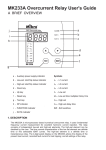
The indicators display the status of the system as follow:
Indicator
Aux
0
1
1
l> l>> FUNC DT
Status
0 0
0
0 No Auxiliary power supply.
0 0
X
X Normal condition, no tripping.
1 0
X
X Low-set overcurrent triggered,
time delay countdown started.
0 1
X
X High-set overcurrent triggered,
time delay countdown started.
B 0
B
B Low-set tripped,
DT LEDs show tripped value.
1
1
1
0
1
X
B
X
B
B
High-set tripped,
DT LEDs show tripped value.
B
1
Programming mode.
Table 1: System Status
1 = ON
0 = OFF
X= don’t care, not blinking
B = blinking DT = DATA FUNC = FUNCTION
Indicator
FUNCTION
. 0
0
4
5
6
7
8
DP
off
blink
off
off
off
off
off
DATA
Earth fault current.
Previous tripped current.
Low-set current setting.
Time multiplier/delay time setting.
High-set current setting.
High-set delay time setting.
Soft switch setting.
Table 2: FUNCTION Code
Note:
Under normal operating condition, The 4-digit display
is off. When the RESET key is pressed, the 4-digit
display will light up. The display will switch off
automatically after 6 minutes if no further key is
pressed.
Step 1: Press RESET key until the function digit
shows required function.
Step 2: Press the UP
simultaneously to
mode. The function
indicates the relay
Step 3: Use the UP or DOWN key to select the
desired value.
Step 4: To save the selected value, press the
UP and DOWN key simultaneously again.
It will exit the programming mode with the
data digits displaying new setting.
To exit programming mode without saving the
selected setting, press the RESET key once.
4. OUTPUT CONTACTS
The MK232A has two set of output contact:
(i) CONTACT R1 - linked to trip signal.
(i) CONTACT R2 - linked to trip or start signal.
The output contact can be programmed to be either
auto reset type or manual reset type.
For auto reset type, the contact remain activated until
the fault current is removed.
For manual reset type, the contact remain activated.
5. SOFT SWITCHES
The MK232A incorporates 4 soft switches for system
configuration. When the function digit shows “8”, the
relay is in soft switch setting mode.
3. PUSH-BUTTONS OPERATION
a) Trip test
Press the “TEST” button to simulate a trip
b) Trip reset
Press the “RESET” button to reset the relay when
tripped.
c) View setting
When the relay is not under tripped condition,
pressing the “RESET” button will scroll through the
various functions.
and DOWN key
enter programming
digit will blinks to
is in programming
“ ” switch value (SVL)
switch number (SW)
SW SVL
1
System configuration
00 Contact R1 linked to trip signal auto reset type.
01 Contact R1 linked to trip signal manual reset type.
2
00 Contact R2 linked to trip signal auto reset type.
01 Contact R2 linked to trip signal manual reset type.
10 Contact R2 linked to signal auto reset type.
11 Contact R2 linked to signal manual reset type.
3
00 Low-set normal inverse curve 3/10.
01 Low-set normal inverse curve 1.3/10.
02 Low-set long time inverse curve.
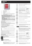
Figure 1: Scroll sequence
d) Program setting
Only function codes from 4 to 8 can be programmed.
03 Low-set very inverse curve.
04 Low-set extremely inverse curve.
05 Low-set definite time.
4
00 High-set disabled.
01 High-set enabled.
Table 3: Soft switch setting