1
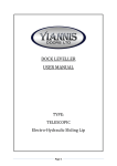
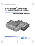
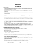
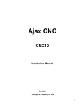
RTK3 Logic Controller User Manual
Revised 6-24-08
1 of 16
svn://software/hardware/RTK3/docs/rtk3_man.doc
MRR 6/24/08 9:03 AM
Overview
The RTK3 is intended to simplify and expedite control wiring. Centroid’s PLCIO2 was the starting
point for the RTK3, and modifications were aimed at increasing efficiency on standard system configurations.
To reduce the number of connections in the control cabinet, input and most output voltages are standardized.
Logic and input power supplies are built in to the RTK3 to further simplify installation. Positive locking
connectors on pre-assembled cables eliminate the need to individually connect each wire to the RTK3.
Much remains common between the PLCIO2 and RTK3. The motion control card (CPU10 or
compatible) connected to the RTK3 must be equipped with an IO2PIC chip (see TB133 for upgrade procedure).
PLCCOMP or XPLCCOMP or both PLC compilers can be used with the RTK3, just like the PLCIO2. The
RTK3 also retains the Fast I/O feature, which is now dedicated to a sourcing sensor input and relay output.
There are three layers in the RTK3 to minimize footprint and maximize cabinet efficiency. Only rarely
used connectors are located on the backside of the unit to allow mounting against the cabinet wall if necessary.
The bottom board has six mounting holes for direct attachment to standoffs. See the “RTK3 Mounting
Dimensions” section for mounting standoff configuration. The bottom, or logic, board is home to the logic
controller’s processor, input isolators, analog output section, output drivers, and power supply section. This is
where the fiber optic and almost all input connections are made. The middle board has 10 relays, one logic
input, and two power inputs. Various voltage and load levels are controlled by relays on the middle board. The
top board is equipped with 110VAC outputs and the 110VAC power input connector.
RTK3 System Constraints
The lube pump output must be either 220VAC or 110VAC single phase. In addition, the E-stop power
loop must be 24VAC, solenoids and lights must be 110VAC, and sensors must be compatible with 24VDC
inputs when using an RTK3.
2 of 16
svn://software/hardware/RTK3/docs/rtk3_man.doc
MRR 6/24/08 9:03 AM
Wiring Concept Visual Comparison
Previous ATC Wiring Sample
Transformer
PC
Inverter
Estop Contactor
Power Supply
Intermediate Terminal Strip
PLCIO2
Servo Drive
Intermediate Terminal Strip
Carousel Motor Contactor
Flood Pump Contactor
RTK3 Wiring Sample
Transformer
PC
Estop Contactor
Inverter
RTK3
Servo Drive
Note the simplified layout and wiring enabled by the RTK3. Fewer individual wires (thin lines) are
used and intermediate terminal block connections are reduced. Cables (thick lines) with quick connect ends
replace many individual wires. Integrated components and specialized connection points on the RTK3 reduce
the quantity of external hardware required. These advantages allow for quicker, more organized, more compact
and more reliable panel wiring.
3 of 16
svn://software/hardware/RTK3/docs/rtk3_man.doc
MRR 6/24/08 9:03 AM
Power Connection
Three power connections are necessary on a full RTK3 installation. Five position plugs are used for the
220VAC and 24VAC power inputs. Three wires are positioned uniquely in the housing to prevent operation
with incorrect voltage connections. Screw terminals on the top board are used for 100VAC connection.
The 220VAC input supplies the 220VAC lube and spindle cooling fan outputs. The 110VAC input
powers the on board power supply as well as 110VAC outputs. The E-stop output and configurable outputs
may use the 24VAC input.
Input Wiring
All inputs on the RTK3 are optically isolated and 24VDC powered. Some inputs are sourcing and
others are sinking, see the “Input Map” section for details. The two basic input configurations are shown
below.
Internal Circuitry
Internal Circuitry
Sourcing Input
Sinking Input
+24 VDC
+24 VDC
INP UT P OW ER
INP UT
INP UT
INP UT GROUND
24 GROUND
24 GROUND
Either type of input may be used with a switch. Sourcing inputs may be used with sinking sensors that are
capable of sinking 15mA at 24VDC. Sinking inputs may be used with sourcing sensors that provide 15mA at
24VDC. Compare sensor and RTK3 input specifications using the “RTK3 Specifications” table to ensure
compatibility. Two wire sensors should not be used with the RTK3, since they normally do not meet the “Input
On Voltage” and “Input Off Voltage” specifications. Care must be taken to wire each input correctly, as the
cable for each input has signals that are not used in all cases. These include 24VDC and Input Ground for
powering sensors and a shield connection that should normally be connected only to the RTK3. The 24VDC
supply fuse is located on the bottom (logic) board. The “DIGITIZE PROBE” connector has an additional fuse
on its 24VDC supply pin, which can also be found on the logic board. These fuses are in series such that the
digitizer fuse could fail without affecting other inputs. However, a short in any other 24VDC circuit will blow
the main 24VDC fuse, causing a loss of all input voltages.
Connectors are available on the RTK3 to plug in limit and fault inputs from a Centroid DC brushed
servo drive. The “DRV FAULT” and “LIMITS TO DRIVE” headers are intended only for allowing straight
through cable connections to a drive. Limit switch wiring should be done from the “X- / X+ / Y- / Y+ LIMITS”
and “W+ / W- / 5+ / 5- LIMITS” headers. When using a Centroid DC brushed servo drive with an RTK3, the
“G” and “5” power DIP switches on the drive should be turned on.
4 of 16
svn://software/hardware/RTK3/docs/rtk3_man.doc
MRR 6/24/08 9:03 AM
Output Wiring
Several output types are present on the RTK3 to reduce wiring time when interfacing with specific
components. These include 110VAC, 220VAC, and 3 phase outputs as well as a 24VAC and an analog output.
Open collector and relay contact outputs are also available for more general application. See the “Output Map”
section for more information.
Each power relay output is protected by a fuse. The “DOOR FAN” and “CONSOLE” unswitched
110VAC outputs are also fuse protected. Fuses are 5x20mm and should be rated equal to or less than the
ratings printed on the RTK3 for safety. Signal relays, such as those on the inverter outputs, are not fuse
protected.
Internal Circuitry
Internal Circuitry
Internal Circuitry
110VAC Output
220VAC Output
Relay Output
110 VAC H
220 VAC L1
Out put Com m on
Out put
Out put
Out put
Internal Circuitry
Flood Pump Output
Internal Circuitry
Open Collector Output
FLOOD OUT P UT
+5 VDC
FLOOD COM M ON
OUT 3
Out put
24 AC1
1
2
JB5
5 GROUND
5 of 16
svn://software/hardware/RTK3/docs/rtk3_man.doc
MRR 6/24/08 9:03 AM
Internal Circuitry
Carousel Outputs
CAROUSEL DIRECT ION 1
CAROUSEL DIRECT ION 2
OUT 5
CAROUSEL COM M ON
OUT 31
24 AC1
1
2
JB6
Configurable Outputs
Outputs 11 and 37 may be configured as 24VAC or relay contact outputs. These outputs are routed to
the “AUX 2 / CHILLER” connector. The configurable output jumper settings must be verified before
connecting these outputs to prevent damage to the RTK3 or associated hardware.
Internal Circuitry
Configurable Relay Outputs
OUT P UT
24 AC1
1
2
J1 or J3
24 AC2
1
2
OUT P UT COM M ON
J2 or J4
24VAC Output Setting
Pin 1
6 of 16
Relay Contact Output Setting
Pin 1
J1 or J3
J1 or J3
J2 or J4
J2 or J4
svn://software/hardware/RTK3/docs/rtk3_man.doc
MRR 6/24/08 9:03 AM
Spindle Outputs
The RTK3 is equipped with an analog output and specialized relay outputs to simplify spindle drive
wiring. The analog output has a 12-bit resolution and can be configured for 0 to +5VDC or 0 to +10VDC
output. The analog ground should not be connected to other grounds on the RTK3. All input and output
functions required for a standard inverter connection are located on the 15 pin “INVERTER” connector.
Internal Circuitry
Spindle Drive Outputs
SP INDLE DRIVE RESET
OUT 15
SP INDLE OUT P UT COM M ON
SP INDLE DRIVE RESET COM M ON
SP INDLE ORIENT
Internal Circuitry
OUT 10
Analog Output
+12 VDC
SP INDLE ENABLE
OUT 14
-
SP INDLE ANALOG OUT P UT
1
+
ANALOG GROUND
1
SP INDLE REVERSE
OUT 13
Jumper Setting for Direction Run Through Enable
Jumper Setting for Direction Pulled to Common
Pin 1
7 of 16
SP INDLE FORW ARD
2
J5
ANALOG
-12 VDC GROUND
J4
SP INDLE DIRECT ION COM M ON
2
J4
Pin 1
J5
svn://software/hardware/RTK3/docs/rtk3_man.doc
J4
J5
MRR 6/24/08 9:03 AM
Analog Output Adjustment
Output voltage range can be set to 0 to +5VDC or 0 to +10VDC by setting jumpers J1, J2, and J3
according to the diagrams below. Trimming the output can be accomplished with VR1 and VR2
potentiometers. See the “RTK3L (Bottom) Board Connections” diagram for the location of adjustment
hardware. The analog levels are adjusted at the factory for the 0 to +10VDC range, so only slight adjustments
should be needed for each installation. Only adjust the “OFFSET” potentiometer (pot) (VR2) at the minimum
possible spindle speed. This adjustment is intended only to null the voltage level when 0 RPM is commanded.
The “GAIN” pot (VR1) should be used at maximum speed to match actual RPM with commanded RPM.
Adjustments to the analog output should be very minor and cannot be used to compensate for incorrect inverter
or control settings.
0 to 10 VDC Jumper Settings
0 to 5 VDC Jumper Settings
Pin 1
J3
Pin 1
J2
J1
J3
J2
J1
Emergency Stop Connector
The E-stop connector has an input and output, unlike most RTK3 connectors. The input notifies the
control of an external E-stop press. The output allows an E-stop to be triggered by the PLC program. Because
the E-stop connector sources 24VAC, a 24VAC contactor coil must be used. This reduces the number of
connections at the cost of some versatility.
Internal Circuitry
24VAC E-stop Output
24 AC1
Out put
OUT 1
8 of 16
svn://software/hardware/RTK3/docs/rtk3_man.doc
MRR 6/24/08 9:03 AM
Fast I/O Operation
The Fast I/O is a hard-coded function that is enabled when output 40 is turned on in the PLC program.
The Fast I/O immediately turns off output 31 when a falling edge is detected on input 26. This is done
immediately before sending any data back to the control. The function is self-resetting - after output 31 is
turned off, output 40 must be turned on again in order to reactivate the Fast I/O. Using the Fast I/O prevents the
carousel from moving too far due to communication delays. When output 40 is off, output 31 and input 26
work normally. In the RTK3 implementation of the Fast I/O, input 26 is dedicated to a sourcing tool counter
sensor and output 31 controls the carousel enable relay. Output 40 is not a physical output, since using this
output for purposes other than Fast I/O enable could cause confusion.
Timing Diagram - Fast I/O Enabled
Timing Diagram - Normal PLC Operation
OUT40
OUT40
INP26
INP26
OUT31
OUT31
30mS
6mS
Status Indicator LEDs
Six green indicator LEDs (lights) located on the bottom board display RTK3 status. All six LEDs will
be lit under normal operating conditions. Five of the LEDs indicate the presence of required operating voltages.
The 110VAC input feeds the power supply to generate these voltages. The “PLC OK” LED lights when the
RTK3 and motion control card (CPU10) have a working communication link. This LED will not be lit as soon
as power is applied. After the control software (CNC10) has initialized the motion control card, communication
can be established with the RTK3, which lights the “PLC OK” LED.
9 of 16
svn://software/hardware/RTK3/docs/rtk3_man.doc
MRR 6/24/08 9:03 AM
Input Map
Number
1
2
3
4
5
6
7
8
9
10
11
12
13
14
15
16
17
18
19
20
21
22
23
24
25
26
27
28
29
30
31
32
33
34
35
36
37
38
39
40
41
42
43
44
45
46
47
48
49
50
51
52
53
54
55
56
57
58
59
60
61
62
* Fast I/O Related
10 of 16
Input Specification
Function
Type
Board
Connection Location
Connector
Pin
X- Limit
X+ Limit
Y- Limit
Y+ Limit
Z- Limit
Z+ Limit
W- Limit
W+ Limit
5th- Limit
5th+ Limit
Emergency Stop
Servo Drive Fault
TT1
Probe
Probe Detect
Error Check
Door Interlock
Low Lube
Spindle Zero Speed
Spindle At Speed
Spindle Orient Complete
Tool Clamped
Tool Unclamped
Tool Release Switch
Spindle Drive Fault
Tool Counter *
Carousel Out / TP Up
Carousel In / TP Dwn
Auxiliary 1
Rotary Home
Rotary Clamped
Air Pressure Low
NOT USED
NOT USED
NOT USED
NOT USED
NOT USED
NOT USED
NOT USED
NOT USED
NOT USED
NOT USED
NOT USED
NOT USED
NOT USED
NOT USED
NOT USED
NOT USED
NOT USED
NOT USED
NOT USED
NOT USED
NOT USED
NOT USED
NOT USED
NOT USED
NOT USED
NOT USED
Range 3 / Arm Clamp
Range 2 / Arm Stop
Range 1 / Arm Home
Spindle Chiller OK
Sourcing
Sourcing
Sourcing
Sourcing
Sourcing
Sourcing
Sourcing
Sourcing
Sourcing
Sourcing
Sourcing
Sourcing
Sourcing
Sourcing
Sourcing
Internal
Sourcing
Sourcing
Sourcing
Sourcing
Sourcing
Sourcing
Sourcing
Sourcing
Sourcing
Sinking
Sinking
Sinking
Sinking
Sourcing
Sourcing
Sourcing
N/A
N/A
N/A
N/A
N/A
N/A
N/A
N/A
N/A
N/A
N/A
N/A
N/A
N/A
N/A
N/A
N/A
N/A
N/A
N/A
N/A
N/A
N/A
N/A
N/A
N/A
Sinking
Sinking
Sinking
Sinking
Bottom
Bottom
Bottom
Bottom
Bottom
Bottom
Bottom
Bottom
Bottom
Bottom
Bottom
Bottom
Bottom
Bottom
Bottom
N/A
Bottom
Middle
Bottom
Bottom
Bottom
Bottom
Bottom
Bottom
Bottom
Bottom
Bottom
Bottom
Bottom
Bottom
Bottom
Bottom
N/A
N/A
N/A
N/A
N/A
N/A
N/A
N/A
N/A
N/A
N/A
N/A
N/A
N/A
N/A
N/A
N/A
N/A
N/A
N/A
N/A
N/A
N/A
N/A
N/A
N/A
Bottom
Bottom
Bottom
Bottom
X- / X+ / Y- / Y+ LIMITS
X- / X+ / Y- / Y+ LIMITS
X- / X+ / Y- / Y+ LIMITS
X- / X+ / Y- / Y+ LIMITS
Z+ / Z- LIMITS
Z+ / Z- LIMITS
W+ / W- / 5+ / 5- LIMITS
W+ / W- / 5+ / 5- LIMITS
W+ / W- / 5+ / 5- LIMITS
W+ / W- / 5+ / 5- LIMITS
ESTOP
DRV FAULT
TT1 / AUX
DIGITIZE PROBE
DIGITIZE PROBE
N/A
DOOR SWITCH
LOWLUBE
INVERTER
INVERTER
INVERTER
TOOL CLAMP/UNCLAMP
TOOL CLAMP/UNCLAMP
TOOL REL SW
INVERTER
CAROUSEL INPUTS
CAROUSEL INPUTS
CAROUSEL INPUTS
CAROUSEL INPUTS
ROTARY INPUTS
ROTARY INPUTS
AIR LOW
N/A
N/A
N/A
N/A
N/A
N/A
N/A
N/A
N/A
N/A
N/A
N/A
N/A
N/A
N/A
N/A
N/A
N/A
N/A
N/A
N/A
N/A
N/A
N/A
N/A
N/A
AUX SPINDLE INPUTS
AUX SPINDLE INPUTS
AUX SPINDLE INPUTS
AUX SPINDLE INPUTS
1
3
5
7
1
3
1
3
5
7
1
2
1
1
3
N/A
1
1
10
13
11
3
1
1
12
4
2
1
3
1
3
1
N/A
N/A
N/A
N/A
N/A
N/A
N/A
N/A
N/A
N/A
N/A
N/A
N/A
N/A
N/A
N/A
N/A
N/A
N/A
N/A
N/A
N/A
N/A
N/A
N/A
N/A
1
2
3
4
svn://software/hardware/RTK3/docs/rtk3_man.doc
MRR 6/24/08 9:03 AM
Output Map
Number
Output Specification
Function
1
Emergency Stop
2
Lube Pump
2
Lube Pump
3
Flood Pump
4
Mist Solenoid
5
Carousel Direction
6
Carousel Out Solenoid
7
Tool Clamp Solenoid
8
Air Blow Through
9
Carousel In Solenoid
10
Orient
11
Spindle Chiller
12
Spindle Cooling Fan
13
Spindle Direction
14
Spindle Enable
15
Inverter Reset
16
Error Check
17
Spin. Speed Bit 0
18
Spin. Speed Bit 1
19
Spin. Speed Bit 2
20
Spin. Speed Bit 3
21
Spin. Speed Bit 4
22
Spin. Speed Bit 5
23
Spin. Speed Bit 6
24
Spin. Speed Bit 7
25
Spin. Speed Bit 8
26
Spin. Speed Bit 9
27
Spin. Speed Bit 10
28
Spin. Speed Bit 11
29
Gear Change
30
Rotary Clamp Solenoid
31
Carousel Enable *
32
Red Light
33
Green Light
34
Yellow Light
35
Worklight
36
Auxiliary 1
37
Auxiliary 2
38
Auxiliary 3
39
Auxiliary 4
40
Fast I/O Enable *
41
Auxiliary 5^
42
Auxiliary 6^
43
Auxiliary 7^
44
Auxiliary 8^
45
Auxiliary 9^
46
Auxiliary 10^
47
Auxiliary 11^
48
Auxiliary 12^
49
NOT USED
50
NOT USED
51
NOT USED
52
NOT USED
53
NOT USED
54
NOT USED
55
NOT USED
56
NOT USED
57
NOT USED
58
NOT USED
59
Auxiliary 13
60
Auxiliary 14
61
Auxiliary 15
62
Auxiliary 16
* Fast I/O Related
Type
24VAC
220VAC
110VAC
3 PHASE
110VAC
Internal
110VAC
110VAC
110VAC
110VAC
Relay Contact
Configurable
220VAC
Relay Contact
Relay Contact
Relay Contact
Internal
Internal
Internal
Internal
Internal
Internal
Internal
Internal
Internal
Internal
Internal
Internal
Internal
Relay Contact
110VAC
3 PHASE
110VAC
110VAC
110VAC
110VAC
Relay Contact
Configurable
Open Collector
Open Collector
N/A
Open Collector
Open Collector
Open Collector
Open Collector
Open Collector
Open Collector
Open Collector
Open Collector
N/A
N/A
N/A
N/A
N/A
N/A
N/A
N/A
N/A
N/A
Open Collector
Open Collector
Open Collector
Open Collector
Board
Connection Location
Connector
Bottom
Middle
Top
Middle
Top
Middle
Top
Top
Top
Top
Bottom
Middle
Middle
Bottom
Bottom
Bottom
N/A
N/A
N/A
N/A
N/A
N/A
N/A
N/A
N/A
N/A
N/A
N/A
N/A
Middle
Top
Middle
Top
Top
Top
Top
Middle
Middle
Bottom
Bottom
N/A
Bottom
Bottom
Bottom
Bottom
Bottom
Bottom
Bottom
Bottom
N/A
N/A
N/A
N/A
N/A
N/A
N/A
N/A
N/A
N/A
Bottom
Bottom
Bottom
Bottom
ESTOP
220 LUBE
110 LUBE
FLOOD MOTOR
MISTER
N/A
CAR OUT
TOOL CLAMP
AIR BLOW
CAR IN
INVERTER
AUX 2 / CHILLER
SPIN FAN
INVERTER
INVERTER
INVERTER
N/A
N/A
N/A
N/A
N/A
N/A
N/A
N/A
N/A
N/A
N/A
N/A
N/A
AUX1 / RANGE
ROT CLAMP
CAROUSEL MOTOR
RED LIGHT
GRN LIGHT
YEL LIGHT
WORKLIGHT
AUX 1 / RANGE
AUX 2 / CHILLER
AUX DRIVERS 1
AUX DRIVERS 1
N/A
AUX DRIVERS 1
AUX DRIVERS 1
AUX DRIVERS 1
AUX DRIVERS 1
AUX DRIVERS 1
AUX DRIVERS 2
AUX DRIVERS 2
AUX DRIVERS 2
N/A
N/A
N/A
N/A
N/A
N/A
N/A
N/A
N/A
N/A
AUX DRIVERS 2
AUX DRIVERS 2
AUX DRIVERS 2
AUX DRIVERS 2
Pin
4
1
1
1,2,3
1
N/A
1
1
1
1
3
1,2
1
5,6,7
4
1
N/A
N/A
N/A
N/A
N/A
N/A
N/A
N/A
N/A
N/A
N/A
N/A
N/A
1,2
1
1,2,3
1
1
1
1
3,4
3,4
10
9
N/A
7
6
5
4
3
10
9
8
N/A
N/A
N/A
N/A
N/A
N/A
N/A
N/A
N/A
N/A
6
5
4
3
^ Often used to store the tool number
11 of 16
svn://software/hardware/RTK3/docs/rtk3_man.doc
MRR 6/24/08 9:03 AM
RTK3 Specifications
Min.
Typ.
Max.
5 Volt Supply Current
Characteristic
-
1.6
-
A
Unit
24 Volt Supply Current
-
0.6
-
A
Input Pullup Voltage
-
24
-
V
Input On Voltage
22
-
-
V
Input Off Voltage
-
-
1.25
V
Power Relay Output Current
0.01
-
10
Power Relay Output Current
0.01
-
5
Power Relay Output Current
10
-
400
mA @ 100VDC
Signal Relay Output Current
0.001
-
0.5
A @ 125VAC
Signal Relay Output Current
0.001
-
1
A @ 24VDC
Open Collector Output Current
-
-
500
Open Collector Output Voltage
-
5
-
3 Phase Output Load
-
-
0.50
110 VAC Input Current
-
9
28
A @ 250VAC
A @ 30VDC
mA
V
HP @ 250VAC
A
3 Phase Input Current
-
-
Input Operating current
9
11
15
mA
Analog Output Resolution
-
12
-
bits
Analog Output Voltage
0
-
10
V
Analog Output Current
0
1
20
mA
Size: 12*5*4 (W*D*H)
RTK3 Troubleshooting
Symptom
Possible Cause
Corrective Action
All status LEDs out
110VAC not connected
connect 110VAC supply to H7 on top board, check voltage
between 110ACN and 110ACH terminals
F1 Fuse on logic board blown
Return for repair
PLC OK LED out
Motion control card not initialized
Start CNC10 or CNC7 software
Incorrect PIC on motion control card
Install IO2PIC
Fibers faulty or incorrectly connected
Check connections, inspect or swap fibers
+24 LED out
Fuse blown or poor connection
Check +24VDC fuse and fuseclips on bottom board
No digitizer +24VDC
If +24VDC LED is lit, digitizer fuse blown or poor
connection
Check digitizer fuse and fuseclips on bottom board
No analog output or non-linear output
Incorrect Parameter 31 setting
Set P31 to -1
Estop contactor or other 24VAC outputs
not working
24VAC not connected
plug 24VAC cable into 24VAC input on middle board, check
connections and voltage
AUX2 or CHILLER outputs not working Jumpers J1-J4 on Output (middle) board not set
correctly
12 of 16
svn://software/hardware/RTK3/docs/rtk3_man.doc
Refer to page 6 in the manual
MRR 6/24/08 9:03 AM
RTK3 Mounting Dimensions
4.275
12.000
11.800
5.450
5.275
0.200
0.475
0.200
0.500
4.375
5.000
13 of 16
svn://software/hardware/RTK3/docs/rtk3_man.doc
MRR 6/24/08 9:03 AM
Probe Contact Input
24 Ground
Probe Detect Input
24 Ground
Digitizer 24 VDC
Chassis Ground
TT1 / Auxilary1 Input
24 Ground
24 VDC
Chassis Ground
Rotary Home Input
24 Ground
Rotary Clamped Input
24 Ground
24 VDC
Chassis
Ground
Spindle Drive Reset Common
Spindle Output Common
Chassis Ground
RTK3L (Bottom) Board Connections
Estop Input
24 Ground
Pin
1
Pin
1
Pin
1
Pin
1
Pin 1
Pin 1
Pin 1
5 Ground
5 VDC
Auxiliary Output Driver 9
Auxiliary Output Driver 8
Auxiliary Output Driver 7
Auxiliary Output Driver 6
Auxiliary Output Driver 5
Pin 1
Pin 1
Pin 1
Pin 1
Auxiliary Output Driver 4
Auxiliary Output Driver 3
5 Ground
5 VDC
Auxiliary Output Driver 16
Auxiliary Output Driver 15
Auxiliary Output Driver 14
Auxiliary Output Driver 13
Auxiliary Output Driver 12
Auxiliary Output Driver 11
Auxiliary Output Driver 10
Pin 1
Programming Header - Do Not Connect
Pin 1
J1
Analog
Output
Configuration
Jumpers
J2
Pin 1
J3
Analog Offset Pot
Estop Output
24 AC2
Chassis Ground
Z- Limit Input
24 Ground
Z+ Limit Input
24 Ground
24 VDC
Chassis Ground
W- Limit Input
24 Ground
W+ Limit Input
24 Ground
5- Limit Input
24 Ground
5+ Limit Input
24 Ground
24 VDC
Chassis Ground
X- Limit Input
24 Ground
X+ Limit Input
24 Ground
Y- Limit Input
24 Ground
Y+ Limit Input
24 Ground
24 VDC
Chassis Ground
Range1 Input
Range2 Input
Range3 Input
Chiller Input
24 VDC
24 Ground
24 Ground
Chassis Ground
Tool Unclamped Input
24 Ground
Tool Clamped Input
24 Ground
24 VDC
Chassis Ground
Tool Release Switch Input
24 Ground
24 VDC
Chassis Ground
Carousel Out Input
Carousel In Input
Auxiliary 1 Input
Tool Counter Input
24 VDC
24 Ground
24 Ground
Chassis Ground
Pin 1
Air Low Input
24 Ground
24 VDC
Chassis Ground
Pin 1
Door Interlock Input
24 Ground
24 VDC
Chassis Ground
Analog Gain Pot
J5
14 of 16
svn://software/hardware/RTK3/docs/rtk3_man.doc
Fiber Optic 1
Fiber Optic 2
X- Drive Limit
X+ Drive Limit
Y- Drive Limit
Y+ Drive Limit
Z- Drive Limit
Z+ Drive Limit
W- Drive Limit
W+ Drive Limit
24 Ground
Drive 5 VDC
24 Ground
Drive Fault Input
Drive 5 VDC
24 Ground
Fiber Optic 3
Pin
1
Pin
1
Pin
1
Inverter Output Configuration Jumpers
Spindle Drive Reset
Spindle Output Common
Spindle Orient Output
Spindle Enable Output
Spindle Direction Common
Spindle Forward Output
Spindle Reverse Output
Spindle Analog Output
Analog Ground
Spindle Zero Speed Input
Spindle Orient Complete Input
Spindle Drive Fault Input
Spindle At Speed Input
24 Ground
Chassis Ground
J4
MRR 6/24/08 9:03 AM
RTK3O (Middle) Board Connections
24 AC1 Input
Pin 1
Pin 1
24 AC2 Input
Chassis Ground
Chiller Output Common
Chiller Output
Auxiliary 2 Output Common
Auxiliary 2 Output
Chassis Ground
Pin 1
Range Change Common
Range Change Output
Auxiliary 1 Common
Auxiliary 1 Output
Chassis Ground
Chiller Configuration Jumpers
JB1
Pin 1
JB2
Lube Low Input
24 Ground
Pin 1
Auxiliary 2 Configuration Jumpers
JB3
Pin 1
Chassis Ground
JB4
Lube Pump 220 AC1
Pin 1
Lube Pump 220 AC2
Chassis Ground
Spindle Fan 220 AC1
Pin 1
Spindle Fan 220 AC2
Chassis Ground
220 AC1 Input
Pin 1
220 AC2 Input
Chassis Ground
JB5
JB6
15 of 16
svn://software/hardware/RTK3/docs/rtk3_man.doc
Flood Output
Flood Common
24 AC2
Carousel Direction 1
Carousel Direction 2
Carousel Common
24 AC2
MRR 6/24/08 9:03 AM
Air Blow Output
110 ACN
Chassis Ground
Carousel In Output
110 ACN
Chassis Ground
Pin 1
Carousel Out Outpu
110 ACN
Chassis Ground
Pin 1
Tool Clamp Output
110 ACN
Chassis Ground
Pin 1
Pin 1
Chassis Ground
110 ACN
Console 110 ACH
Pin 1
Door Fan 110 ACH
110 ACN
Chassis Ground
RTK3T (Top) Board Connections
110 ACH
110 ACN
Chassis Ground
Pin 1
Pin 1
Pin 1
Pin 1
Pin 1
Pin 1
Pin 1
Pin 1
16 of 16
svn://software/hardware/RTK3/docs/rtk3_man.doc
MRR 6/24/08 9:03 AM
110 Lube Output
110 ACN
Chassis Ground
Mister Output
110 ACN
Chassis Ground
Worklight Output
110 ACN
Chassis Ground
Rotary Clamp Output
110 ACN
Chassis Ground
Red Light Output
110 ACN
Chassis Ground
Green Light Output
110 ACN
Chassis Ground
Yellow Light Output
110 ACN
Chassis Ground