1
Installation Instructions
Instrucciones de instalación
Electronic Lock Indicator (ELI ®)
RK-10855-L, RK-10855-R and
RK-10855-A 2-Sensor Retrofit Kit
t' PS9"9"BOE9"4FSJFT'JGUI8IFFM5PQ
1MBUFT
Kit de indicador electrónico de cierre (ELI®)
RK-10855-L, RK-10855-R y RK-10855-A
Español
English
t1BSBQMBUPTTVQFSJPSFTEFRVJOUBSVFEB9"
9"Z9"
XL-FW10064BM-en-US Rev A
Contents
Contents
Page
Introduction ......................................................................... 2
Notes, Cautions, and Warnings ............................................. 2
Section 1 – Model Identification........................................... 3
Section 2 – General Safety Instructions ................................ 3
Exploded View and Parts List ................................................ 4
Section 3 – Top Plate Removal.............................................. 5
Section 4 – Left-Hand and Air Release Installation................ 7
Contents
Page
Section 5 – Left-Hand and Air Release Harness Installation ..... 8
Section 6 – Right-Hand Release Installation ......................... 9
Section 7 – Right-Hand Release Harness Installation .......... 10
Section 8 – Kingpin Sensor Bracket Installation .................. 11
Section 9 – Sensor Position Check ...................................... 12
Section 10 – Top Plate Installation ..................................... 13
Section 11 – Wire Routing Procedure ................................. 14
Introduction
This manual provides retrofit procedures for installing the
Electronic Lock Indicator System (ELI) for the Holland FW35
series fifth wheels. See page 3 for exact model identification.
NOTE: For Holland replacement components contact
SAF-HOLLAND Customer Service: 888-396-6501.
Throughout this manual, you will notice the terms “NOTE,”
“IMPORTANT,” “CAUTION,” and “WARNING” followed
by useful product information. So that you may better
understand the manual, those terms are defined as follows:
NOTE: Includes additional information to enable accurate
and easy performance of procedures.
Notes, Cautions, and Warnings
You must read and understand all of the procedures presented
in this manual before starting work on any Electronic Lock
Indicator System (ELI) for the Holland FW35 series fifth wheels.
IMPORTANT: Keep this manual in a safe location for
future reference.
Proper tools must be used to perform the maintenance and
repair procedures described in this manual.
NOTE: In the United States, work shop safety requirements
are defined by federal and/or state Occupational
Safety and Health Acts. Equivalent laws may exist
in other countries. This manual is written based
on the assumption that OSHA or other applicable
employee safety regulations are followed by the
location where work is performed.
2
IMPORTANT: Includes additional information that
if not followed could lead to hindered
product performance.
Used without the safety alert symbol,
indicates a potentially hazardous
situation which, if not avoided, may
result in property damage.
Indicates a potentially hazardous
situation which, if not avoided, may
result in minor or moderate injury.
Indicates a potentially hazardous
situation which, if not avoided, could
result in death or serious injury.
XL-FW10064BM-en-US Rev A · 2011-12-02 · Amendments and errors reserved. © SAF-HOLLAND, Inc.
Model Identification
1. Model Identification
This manual contains retrofit procedures for installing an
Electronic Lock Indicator (ELI) on the 3500 Fifth Wheel Top Plate
(XA-351 Series), and for the 3500 LowLube Fifth Wheel Top Plate
(XA-331 Series) manufactured after January 1, 1997, as well as
3500 NoLube fifth wheel top plate (XA-311 Series) (Figure 1).
Figure 1
$-04&%-001
3&-&"4&)"/%-&
The ELI is NOT available for FW3500 fifth wheel top plates
manufactured before December 31, 1996 (Figure 2).
2. General Safety Instructions
#0-5"/%/653&5&/5*0/
'03#3"$,&51*/
Read and observe all Warning and Caution hazard alert messages
in this publication. They provide information that can help prevent
serious personal injury, damage to components, or both.
The Electronic Lock Indicator System (ELI) installation must
be performed by a trained technician using proper tools and
safe procedures.
Figure 2
01&/-001
3&-&"4&)"/%-&
English
IMPORTANT: The Electronic Lock Indicator (ELI) is a tractortrailer fifth wheel coupling aid and is intended
as an additional safety check to assure the
driver of a safe and complete coupling. It
does not eliminate the requirement for a
visual inspection of the fifth wheel. Always
get out of the tractor cab and visually inspect
the fifth wheel coupling before proceeding.
IMPORTANT: Prior to operation of the fifth wheel you must
be thoroughly satisfied that the fifth wheel
has been properly installed on the vehicle.
Failure to properly install, the fifth wheel may
result in tractor trailer separation which, if not
avoided, could result in death or serious injury.
#3"$,&51*/3&5"*/&%*/5&3/"--:
Refer to SAF-Holland Installation Manual XL-FW10008IM-en-US
(available on the Internet at www.safholland.us) for proper
installation procedures.
We recommend only the use of HOLLAND Original Parts.
A list of SAF-HOLLAND technical support locations to supply
SAF-HOLLAND Original Parts can be found at www.safholland.us
or contact our customer service group at 888-396-6501.
Updates to this manual will be published as necessary on the
Internet at www.safholland.us.
XL-FW10064BM-en-US Rev A · 2011-12-02 · Amendments and errors reserved. © SAF-HOLLAND, Inc.
3
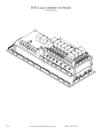
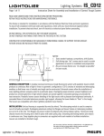
Exploded View and Parts List
,*/(1*/4&/403#3"$,&5
h$"#-&
25:
25:
2
8
$".4&/403#3"$,&5
REQUIRED TOOLS AND SUPPLIES
t&MFDUSJD%SJMM
t5PSRVF8SFODIGUMCT
t8SFODI
t8SFODI
tEJB)PMF$VUUFS
t*TPQSPQZM"MDPIPM
t$MBNQT
t4DJTTPST,OJGF
t)BNNFSPS.BMMFU
w
DESCRIPTION
1
Extension Cable, 2-sensor
XB-10754
PART NO.
QTY.
1
2
Assembly Module, 2-sensor
XB-10758-12
1
3
Harness Subassembly, 2-sensor, LH
XA-10776-L
1
Harness Subassembly, 2-sensor, RH
XA-10776-R
1
Air Release
XA-10766-A
1
4
Cable Tie, Nylon
XB-01961
7
5
4DSFX5ZQF'5ISFBE$VUUJOH
XB-10074
2
6
Roll Pin, 5 mm dia. x 22 mm Large
XB-21-S-5M-22M
2
7
Spring Clip
XB-09976
5
8
Fastener, Reclosable
XB-09782
2
9
Drill Fixture, ELI Kingpin
XA-10067
1
10
Drill Fixture, ELI Lock
XA-10055
11
Loom, Corrugated (part of 1, XB-10754)
12*
8BTIFS0%Y*%
XB-08559
2
13*
3PMMFS*%
XA-1029
1
14
)FY)FBE$BQ4DSFXY
XB-10068
1
15†
-PDL/VU
XB-T-69-A
1
16
Grommet
XB-10086
1
17
Retaining Ring
XB-07398
2
†
18
Drill bit, #1 Split Point
XB-10083
1
19†
Drill bit, #7 Split Point
XB-10084
1
8BTIFS0%Y*%
XB-PW-1732-1-116
1
†
†
20
COMPLETED LEFT-HAND VIEW SHOWN
(UNDERSIDE)
1
1
* Not included in this kit. Items are listed only for reference.
† Included in this kit, but not shown in this drawing.
4
XL-FW10064BM-en-US Rev A · 2011-12-02 · Amendments and errors reserved. © SAF-HOLLAND, Inc.
Installation Instructions
3. Top Plate Removal
NOTE: Some fifth wheel assemblies have replaceable
pocket inserts installed between fifth wheel
top plate and mounting base. Take care when
removing the fifth wheel top plate not to lose
pocket inserts.
Figure 3
3&5&/5*0/
#0-5
5011-"5&
Failure to prevent pocket inserts from
falling out of the top plate could cause
a potentially hazardous situation which,
if not avoided, may result in minor or
moderate injury.
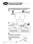
1.
Remove bracket pin retention bolts and nuts from both
sides of fifth wheel top plate (Figure 3).
2.
Using a pry bar, pull bracket retention pins out of fifth
wheel top plate (Figure 3).
3.
Using a lifting device capable of lifting 500 lbs. (227 kg),
remove top plate from mounting base. Place fifth wheel
upside down on a flat, clean working area.
3&5&/5*0/
/65
#3"$,&51*/
13:#"3
English
NOTE: Follow instructions published by lifting device
manufacturer for proper operation of lifting device.
XL-FW10064BM-en-US Rev A · 2011-12-02 · Amendments and errors reserved. © SAF-HOLLAND, Inc.
5
Installation Instructions
4.
Remove retaining rings from lock pins and discard
(Figure 4).
5.
Place drill fixture over lock pins (Figure 5) with “UP”
mark facing up. Clamp the fixture to the fifth wheel.
Figure 4
3&5"*/*/(3*/(4
%SJMMCPUIIPMFTEFFQXJUIB
ESJMMCJU
Remove and discard the fixture. DO NOT reuse the
drill fixture (Figure 6).
NOTE: Before proceeding, make sure the top plate and
work areas are free of chips and burrs.
7.
Install the new retaining rings (Figure 4).
8.
Determine whether your top plate has a right-hand, left-hand,
or air release and follow the appropriate instructions. For
left-hand release and air release, see pages 7 and 8. For
right-hand release, see pages 9 and 10.
Figure 5
&-*,*/(1*/
%3*--'*9563&
Figure 6
%3*--)0-&4
6
XL-FW10064BM-en-US Rev A · 2011-12-02 · Amendments and errors reserved. © SAF-HOLLAND, Inc.
Installation Instructions
4. Left-Hand and Air
Release Installation
Figure 7
$".#0-5
NOTE: For right-hand release instructions, see page 9.
1.
Remove the cam bolt and rotate the cam away from
lug “A” (Figure 7).
2.
Place drill fixture on top of the lugs with the “L” facing
up. Place the cam bolt into the fixture. Insert the locator
pin into the hole in lug “B” (Figure 8).
3.
Clamp drill fixture to the fifth wheel. Drill through lug “A”
with a #7 (0.201) drill bit (Figure 9). Remove and discard
the drill fixture. DO NOT reuse the fixture.
-6(i"w
-6(i#w
Figure 8
&-*-0$,
%3*--'*9563&
-6(i#w
English
$".#0-5
-0$"5031*/
Figure 9
%3*--)0-&
XL-FW10064BM-en-US Rev A · 2011-12-02 · Amendments and errors reserved. © SAF-HOLLAND, Inc.
7
Installation Instructions
4.
Pound the roll pin into the newly drilled hole flush with
the top of the lug (Figure 10).
Figure 10
30--1*/
NOTE: Before installing the sensors and harness, make
sure the top plate and work areas are free of
chips and burrs.
-6(i"w
5. Left-Hand and Air Release
Harness Installation
Cam Sensor Bracket Installation
1.
Clean and lubricate the cam plate. Install cam sensor
bracket under lug “A”. Position hole “B” onto the bottom
of the roll pin.
2.
Once the cam sensor bracket is attached to the roll pin,
line up hole “C” (Figure 11) with the cam bolt hole.
Replace the washer over the cam bolt hole, and rotate
the cam plate back into position (Figure 12). Re-install
the roller and second washer. Finally, guide the hex head
cap screw through the washer, roller, cam plate, washer,
lug, and the cam sensor bracket, add washer. Screw the
new lock nut onto the hex head cap screw and tighten
securely. Check the cam operation for free movement.
Clean away excess grease.
NOTE: When installing the washers, the rounded edge
of the washers must always face the cam plate.
Figure 11
$".#0-5)0-&
-6(i"w
30--1*/
)0-&i#w
Proceed to “Kingpin Sensor Bracket Installation” on page 11.
)0-&i$w
$".4&/403#3"$,&5
Figure 12
)&9)&"%
$"14$3&8
8"4)&3
$".1-"5&
30--&3
8"4)&3
$".4&/403
#3"$,&5
8"4)&3
/&8-0$,/65
8
XL-FW10064BM-en-US Rev A · 2011-12-02 · Amendments and errors reserved. © SAF-HOLLAND, Inc.
Installation Instructions
6. Right-Hand Release Installation
1.
Remove the cam bolt and rotate the cam away from
lug “B“ (Figure 13).
2.
Place drill fixture on top of the lugs with the “R” facing
up. Put cam bolt into the fixture. Insert locator pin into
the hole in lug “A” (Figure 14).
3.
Clamp the drill fixture to the fifth wheel. Drill through
lug “B” with a #7 (0.201) drill bit (Figure 15). Remove
the fixture after drilling. DO NOT reuse the drill fixture.
Figure 13
-6(i#w
$".#0-5
-6(i"w
Figure 14
%3*--'*9563&
-6(i"w
$".#0-5
English
-0$"5031*/
Figure 15
%3*--)&3&
XL-FW10064BM-en-US Rev A · 2011-12-02 · Amendments and errors reserved. © SAF-HOLLAND, Inc.
9
Installation Instructions
4.
Pound the roll pin into the newly drilled hole flush with
the top of the lug (Figure 16).
Figure 16
30--1*/
NOTE: Before installing the sensors and harness, make
sure the top plate and work areas are free of
chips and burrs.
-6(i#w
7. Right-Hand Release
Harness Installation
Cam sensor bracket installation
1.
Clean and lubricate the cam plate. Install cam sensor
bracket under lug “B” (Figure 17). Position hole “B”
onto the bottom of the roll pin.
2.
Once the cam sensor bracket is attached to the roll
pin, line up hole “C” with the cam bolt hole. Place the
washer over the cam bolt hole, and rotate the cam plate
back into position (Figure 17). Re-install the roller and
second washer. Finally, guide the hex head cap screw
through the washer, roller, cam plate, washer, lug, the
cam sensor bracket, and washer (Figure 18). Screw the
new lock nut onto the hex head cap screw and tighten
securely. Check the cam operation for free movement.
Clean away excess grease.
Figure 17
$".#0-5)0-&
-6(i#w
30--1*/
NOTE: When installing the washers, the rounded edge
of the washers must always face the cam plate.
)0-&i#w
)0-&i$w
$".4&/403
#3"$,&5
Figure 18
)&9)&"%
$"14$3&8
$".1-"5&
8"4)&3
30--&3
8"4)&3
$".4&/403#3"$,&5
8"4)&3
/&8-0$,/65
10
XL-FW10064BM-en-US Rev A · 2011-12-02 · Amendments and errors reserved. © SAF-HOLLAND, Inc.
Installation Instructions
8. Kingpin Sensor Bracket Installation
1.
Mount the kingpin sensor bracket to the fifth wheel
(Figure 19) with the thread-cutting screws. Torque
screws to 12 ft.-lbs. DO NOT overtighten the screws.
DO NOT use air or impact tools.
Figure 19
KINGPIN
SENSOR
BRACKET
THREAD-CUTTING
SCREWS
NOTE: The kingpin sensor bracket mounts in the same
position for both left-hand, right-hand and air
release fifth wheels.
2.
Assemble the cable ties and spring clips together before
pressing the clips onto the casting (Figure 20).
3.
Route the harness on the fifth wheel as shown (Figure 21).
Use clips and cable ties to fasten the harness to the fifth
wheel ribs in the locations shown (Figure 21).
NOTE: A left-hand release fifth wheel is shown here. For
a right-hand release, the cam sensor bracket and
wiring are mirrored on the opposite side of the
top plate.
4.
CABLE TIE
Figure 20
Re-install the fifth wheel top plate onto the tractor.
English
413*/($-*1
$"#-&5*&
Figure 21
$"#-&5*&4"/%$-*14
$0//&$503
XL-FW10064BM-en-US Rev A · 2011-12-02 · Amendments and errors reserved. © SAF-HOLLAND, Inc.
11
Installation Instructions
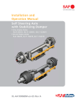
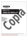
9. Sensor Position Check
1.
Lock the fifth wheel top plate using a Holland lock tester
TF-TLN-5001 and flip the top plate upside down.
2.
Check to make sure the cam plate (Figure 22) and
the kingpin (Figure 23)BSFCPUIXJUIJOPGUIFJS
respective sensor. Pull the cam plate, by hand, away from
the sensor as far as possible when checking the distance.
The cam must not be able to touch the sensor. The cam
sensor bracket may be bent slightly to adjust its distance
from the cam. To avoid damaging the sensor, only pry on
the metal when bending the bracket. DO NOT pry on the
sensor. After adjusting, push cam towards sensor, making
sure they do not touch.
3.
Remove the lock tester and check that the kingpin sensor
is not to close to the locks when they are open. There
TIPVMECFBNJOJNVNPGCFUXFFOUIFTFOTPSBOE
the bottom of the locks (Figure 24). If the distance
is close the kingpin bracket can be bent slightly. After
adjusting away from the locks, recheck the distance to
the kingpin by use of the lock tester.
Figure 22
CAM P
LATE
3/8"
THERE SHOULD BE
A GAP OF 3/8" OR
LESS BETWEEN THE
CAM PLATE AND
THE CAM SENSOR
CAM SENSOR
Figure 23
,*/(1*/
)&"%
,*/(1*/
4&/403
5)&3&4)06-%#&"("10'03-&44
#&58&&/5)&,*/(1*/"/%5)&,*/(1*/4&/403
Figure 24
-0$,4
,*/(1*/
4&/403
.*/*.6.#&58&&/4&/403
"/%#0550.0'-0$,4
12
XL-FW10064BM-en-US Rev A · 2011-12-02 · Amendments and errors reserved. © SAF-HOLLAND, Inc.
Installation Instructions
10. Top Plate Installation
1.
Visually inspect both pocket inserts for excessive wear, chips,
cracks or gouges. If any of these conditions are found, the
pocket insert(s) must be replaced (Figure 25). For pocket
insert replacements, contact SAF-HOLLAND Customer
Service and request RK-PKT-2.
2.
If pocket inserts are dislodged from fifth wheel casting,
clean pocket area of casting and apply a strip of double
face tape in bottom of pockets. Install pocket inserts by
pressing them down into the pocket areas (Figure 26).
3.
Using a lifting device capable of lifting 500 lbs. (227 kg),
install fifth wheel top plate onto its mounting base.
Figure 25
10$,&5*/4&35
NOTE: Follow instructions published by lifting device
manufacturer for proper operation of lifting device.
4.
Install bracket pins through fifth wheel casting and
mounting base and secure by installing the bracket pins
retention bolts and nuts (Figure 27). Torque retention
CPMUTOPUUPFYDFFEGUMCT/tN
Figure 26
English
10$,&5
*/4&35
10$,&5
"3&"
%06#-&
'"$&5"1&
Figure 27
5011-"5&
3&5&/5*0/#0-5
3&5&/5*0//65
#3"$,&51*/
XL-FW10064BM-en-US Rev A · 2011-12-02 · Amendments and errors reserved. © SAF-HOLLAND, Inc.
13
Installation Instructions
11. Wire Routing Procedure
1.
2.
Figure 28
Mount the display box in the cab so that it is easily
visible and accessible to the driver. Clean the dash and
display box mounting surfaces with isopropyl alcohol,
and allow to air dry. Use the provided, re-closable
adhesive fastener to mount the display box on the dash.
&95&/4*0/$"#-&
*/4*%&5)&-00.
(30..&5
Route the cable on the Electronic Lock Indicator (ELI)
display box to approximately where the 25' extension
cable will enter the cab.
3.
Install corrugated loom around extension cable
(Figure 28).
4.
Cut one (1) slit into the grommet (Figure 29).
5.
Wrap the grommet around the 25' extension cable in the
approximate location where it will enter the cab.
$0336("5&%-00.
%SJMMBEJBNFUFSVUJMJUZIPMFJOUIFDBCNBLJOH
sure that there are no obstructions near the drilling area.
7.
Run the end of the 25' extension cable with the power
lines through the utility hole and into the cab.
8.
Install the 1-amp fuse, which is included with the
extension cable (Figure 30).
B4USJQPGJOTVMBUJPOGSPNUIF3&%FYUFOTJPODBCMF
power wire and the tractor’s positive (+) power wire.
It is recommended that a switched terminal in the
main fuse box be used so that power is supplied
when the ignition is turned on.
Figure 29
$654-*5
(30..&5
b. Insert the wires into each end of the fuse holder.
c. Crimp the terminal through the fuse holder body.
Failure to connect a voltage source that
matches the specification on the box
will result in a damaged and inoperable
display box.
9.
Connect the 2-wire power cable from the extension cable to
a 12- or 24-volt power supply. (The back of each display
box is marked with 12- or 24-VDC.) Be sure to connect the
RED wire with the fuse — as outlined in Step 8 — to the
positive (+) terminal, and the BLACK wire to the (-) terminal.
Figure 30
'64&)0-%&3
453*1
453*1
*/4&35
*/4&35
$3*.1)&3&
453*11&%8*3&
3&%&95&/4*0/
108&38*3&
"55"$)104*5*7&108&38*3&50"48*5$)&%
5&3.*/"-*/5)&."*/'64	
14
XL-FW10064BM-en-US Rev A · 2011-12-02 · Amendments and errors reserved. © SAF-HOLLAND, Inc.
Installation Instructions
10. Connect the 25' extension cable to the ELI display box
cable inside the cab.
11. Press the grommet into position in the utility hole. Apply
sealant to the grommet and extension cable to prevent
moisture intrusion into the cab.
Figure 31
3065&&95&/4*0/$"#-&
'30.$"#50'*'5)8)&&12V
12. Route the 25' extension cable from the cab to the fifth
wheel (Figure 31).
13. Route the wire clear of pinch points.
NOTE: For sliding fifth wheels, be sure to leave enough
slack for travel and route the wire clear of pinch
points. It can be helpful to route the wire through
an existing coiled air line.
14. Secure the 25' extension cable so that it is free of
interference from the fifth wheel articulation, brake
lines, light cord, drive line etc.
15. Connect the 25' extension cable to the wire harness on
the fifth wheel (Figure 32).
16. Test ELI for proper operation:
Figure 32
a. Make sure the fifth wheel locks are open.
$0//&$5&95&/4*0/$"#-&
508*3&)"3/&44
English
b. Turn on the ignition/power. The ELI display should
run through a short system check, shown by the brief
illumination of the three display icons (Figure 33).
After the system check is complete, the yellow
“Ready to Couple” icon should be illuminated.
NOTE: If the display does not illuminate or an icon
other than the yellow “Ready to Couple” icon is
illuminated, proceed directly to the SAF-HOLLAND
ELI Troubleshooting Guide XL-FW10063TS-en-US.
c. Lock the fifth wheel top plate using a Holland lock tester
(TF-TLN-5001). The green “Closed Lock” icon should
be illuminated to indicate a proper coupling. If the
green icon does not appear:
t0QFOUIFMPDLTXJUIUIFMPDLUFTUFSBOESFMPDLXIJMF
observing how quickly the handle and cam plate move
into position. If the mechanism is sluggish; lubricate
the cam, yoke tips and the handle according to the
procedures found in your fifth wheel owner’s manual.
t3FMPDLUIFGJGUIXIFFMBHBJOXIJMFPCTFSWJOHUIF
operation of the locking mechanism.
t*GUIFGJGUIXIFFMMPDLJOHNFDIBOJTNJTPQFSBUJOH
correctly and the green “Closed Lock” icon still does
not illuminate, proceed directly to the SAF-HOLLAND
ELI Troubleshooting Guide XL-FW10063TS-en-US.
For operating and maintenance instructions, see SAF-HOLLAND
ELI Owner's Manual XL-FW10062UM-en-US.
XL-FW10064BM-en-US Rev A · 2011-12-02 · Amendments and errors reserved. © SAF-HOLLAND, Inc.
Figure 33
0/%"4)%*41-":
3&"%:50$061-&
'*'5)8)&&-*$0/*4:&--08
1301&3$061-&
$-04&%-0$,*$0/*4(3&&/
*.1301&3$061-&
01&/-0$,*$0/*4'-"4)*/(3&%
15
THIS PAGE INTENTIONALLY BLANK
Instrucciones de instalación
Kit de indicador electrónico
de cierre (ELI®) RK-10855-L,
RK-10855-R y RK-10855-A
t1BSBQMBUPTTVQFSJPSFTEFRVJOUBSVFEB9"
9"Z9"
XL-FW10064BM-es-US Rev A
Contenido
Contenido
Página
Introducción .............................................................................. 18
Notas, precauciones y advertencias .......................................... 18
Sección 1 – Identificación de modelo ........................................ 19
Sección 2 – Instrucciones generales de seguridad .................... 19
Vista esquemática y lista de piezas ........................................... 20
Sección 3 – Desmontaje de la placa superior ............................ 21
Sección 4 – Instalación de izquierda y liberación neumática .... 23
Contenido
Página
Sección 5 – Instalación de arnés de liberación neumática
o izquierda ............................................................ 24
Sección 6 – Instalación de liberación a la derecha .................... 25
Sección 7 – Instalación de arnés de liberación a la derecha ..... 26
Sección 8 – Instalación de soporte de sensor del perno rey ...... 27
Sección 9 – Comprobación de posición del sensor ................... 28
Sección 10 – Instalación de la placa superior............................ 29
Sección 11 – Procedimiento para el tendido de cables .......... 300
Introducción
Este manual muestra procedimientos de actualización para
instalar el Sistema indicador electrónico de cierre (ELI) para
quinta rueda serie FW35 de Holland. Vea en la página 3 la
identificación exacta de los modelos.
NOTA: Para obtener repuestos Holland comuníquese con
Servicio al cliente de SAF-HOLLAND: 888-396-6501.
Notas, precauciones y advertencias
Debe leer y comprender todos los procedimientos presentados en
este manual antes de comenzar a trabajar en cualquier Sistema
indicador electrónico de cierre (ELI) para las quintas ruedas serie
FW35 de Holland.
IMPORTANTE: Guarde este manual en un lugar seguro para
consultarlo en el futuro.
Se deben usar las herramientas adecuadas para practicar los
procedimientos de mantenimiento y reparación descritos en
este manual.
NOTA: En Estados Unidos los requisitos de seguridad en el
taller están definidos por leyes de salud y seguridad
ocupacional federales o estatales (OSHA). Es posible
que existan leyes equivalentes en otros países. Este
manual se escribió basándose en la suposición de
que se siguen las normas de seguridad de empleados
de la OSHA u otras normas aplicables en el lugar en
que se ejecute el trabajo.
18
A lo largo de este manual, usted encontrará los términos “NOTA”,
“IMPORTANTE”, “PRECAUCIÓN” y “ADVERTENCIA” seguidos de
información importante sobre el producto. Para que comprenda
mejor el manual, esos términos se definen en la forma siguiente:
NOTA: Incluye información adicional para permitir la realización
más sencilla y exacta de los procedimientos.
IMPORTANTE: Incluye información adicional que, de no
atenderse podría ocasionar una disminución
en el rendimiento del producto.
PRECAUCIÓN
Sin el símbolo de alerta de seguridad indica
una situación con riesgo potencial que, si no
se evita, puede provocar daños materiales.
PRECAUCIÓN Indica una situación con riesgo potencial
que, si no se evita, puede provocar lesiones
menores o moderadas.
ADVERTENCIA Indica una situación con riesgo potencial
que, si no se evita, puede provocar la
muerte o lesiones graves.
XL-FW10064BM-es-US Rev A · 2011-08-02 · Amendments and errors reserved. © SAF-HOLLAND, Inc.
Identificación del modelo
1. Identificación del modelo
Este manual contiene procedimientos para instalar un Indicador
electrónico de cierre (ELI) en el plato superior de la quinta rueda
3500 (Serie XA-351), y para el plato superior de quinta rueda
LowLube 3500 (Serie XA-331), fabricadas después del 1 de enero
de 1997, así como el plato superior de quinta rueda NoLube
3500 (Serie XA-311) (Figura 1).
Figura 1
."/*+"%&
-*#&3"$*»/$&33"%0
El ELI NO está disponible para platos superiores de quinta rueda
FW3500 fabricadas antes del 31 de diciembre de 1996 (Figura 2).
2. Instrucciones generales de seguridad
3&5&/$*»/%&1&3/0:56&3$"
1"3"1&3/0%&-401035&
Lea y observe todos los mensajes de alerta de riesgo de Advertencia
y precaución de esta publicación. Proporcionan información que
puede ayudar a prevenir lesiones personales graves, daño a los
componentes, o ambos.
IMPORTANTE: El Indicador electrónico de cierre (ELI) es
un auxiliar de acople de quinta rueda de
tractocamión-remolque y su objetivo es ser
una comprobación de seguridad adicional
para que el conductor se asegure de un
acople seguro y completo. No elimina el
requisito de una inspección visual de la
quinta rueda. Salga siempre de la cabina
del tractocamión e inspeccione visualmente
el acople antes de proceder.
IMPORTANTE: Antes de operar la quinta rueda debe
convencerse plenamente de que ésta se
instaló correctamente en el vehículo.
Figura 2
."/*+"%&
-*#&3"$*»/"#*&350
Español
La instalación del Sistema indicador electrónico de cierre (ELI)
la debe ejecutar un técnico capacitado adecuadamente usando
herramientas adecuadas y siguiendo procedimientos seguros.
1&3/0%&-401035&3&5&/*%0
*/5&3/".&/5&
ADVERTENCIA El no instalar la quinta rueda correctamente
puede causar una separación entre el
tractocamión y el remolque que, de no
evitarse, podría producir la muerte o
lesiones graves.
Consulte el Manual de instalación SAF-Holland XL-FW10008IM-sx-US
(disponible en Internet en www.safholland.us) para conocer
los procedimientos de instalación correctos.
Recomendamos usar solamente repuestos originales HOLLAND.
Se puede encontrar una lista de lugares de asistencia técnica de
SAF-HOLLAND que suministran repuestos originales SAF-HOLLAND
en www.safholland.us o puede comunicarse con nuestro
grupo de servicio al cliente en 888-396-6501.
Las actualizaciones a este manual se publicarán según sea
necesario en Internet en www.safholland.us.
XL-FW10064BM-es-US Rev A · 2011-08-02 · Amendments and errors reserved. © SAF-HOLLAND, Inc.
19
Vista esquemática y lista de piezas
401035&%&4&/403%&-1&3/03&:
$"#-&%&h
$"/5
$"/5
2
8
HERRAMIENTAS Y SUMINISTROS NECESARIOS
t5BMBESPFMÏDUSJDP
t5PSRVÓNFUSPQJFTMCT
t-MBWFEF
t-MBWFEF
t4BDBCPDBEPTEFEJÈN
t"MDPIPMJTPQSPQÓMJDP
t"CSB[BEFSBT
t5JKFSBTDVDIJMMP
t.BSUJMMPPNB[P
NO.
DESCRIPCIÓN
NO. DE PARTE
CANT.
1
Cable de extensión, 2 sensores
XB-10754
1
2
Módulo de ensamble, 2 sensores
XB-10758-12
1
3
Subensamble de arnés, 2 sensores, LH
XA-10776-L
1
Subensamble de arnés, 2 sensores, RH
XA-10776-R
1
Liberación neumática
XA-10766-A
1
4
Amarra para cable, nylon
XB-01961
7
5
5PSOJMMP5JQP'BVUPSSPTDBOUF
XB-10074
2
6
Perno de rodillo, 5 mm diám. x 22 mm
de long.
XB-21-S-5M-22M
2
7
Clip de resorte
XB-09976
5
8
Sujetador, recerrable
XB-09782
2
9
Accesorio para taladro, perno rey ELI
XA-10067
1
10
Accesorio para taladro, cierre ELI
XA-10055
11
Conducto, corrugado (parte de 1, XB-10754)
12*
"SBOEFMB%FYUY%*OU
XB-08559
2
13*
SE MUESTRA VISTA IZQUIERDA TERMINADA
(LADO INFERIOR)
1
1
3PEJMMP%*OU
XA-1029
1
14
Tornillo de cabeza hueca hexagonal
Y
XB-10068
1
15†
5VFSDBEFTFHVSJEBE
XB-T-69-A
1
16
Pasacables
XB-10086
1
17
Anillo de retención
XB-07398
2
18†
Broca, #1 punta partida
XB-10083
1
19†
Broca #7 Punta partida
XB-10084
20†
"SBOEFMB%&YUY%*OU
XB-PW-1732-1-116
†
401035&%&4&/403%&-&7"
1
1
* No incluído en este juego. Los elementos se mencionan sólo como referencia.
† Se incluye en la lista pero no se muestra en el dibujo.
20
XL-FW10064BM-es-US Rev A · 2011-08-02 · Amendments and errors reserved. © SAF-HOLLAND, Inc.
Instrucciones de instalación
3. Desmontaje del plato superior
NOTA: Algunos ensambles de quinta rueda tienen insertos
instalados entre el plato superior de la quinta
rueda y la base de montaje. Al desmontar el plato
superior de la quinta rueda tenga cuidado de no
perder los insertos.
PRECAUCIÓN
1.
Figura 3
1-"50461&3*03
1&3/0%&3&5&/$*»/
El no evitar la caída de los insertos de
la placa superior podría causar una
situación potencialmente peligrosa que,
si no se evita, puede causar lesiones
menores o moderadas.
Retire los pernos de retención y las tuercas del perno del
soporte de ambos lados del plato superior de la quinta
rueda (Figura 3).
2.
Usando una palanca, saque los pasadores de retención
de la placa superior de la quinta rueda (Figura 3).
3.
Usando un dispositivo de elevación capaz de levantar
500 libras (227 kg), retire el plato superior de la base de
montaje. Ponga la quinta rueda boca abajo en un área de
trabajo plana y limpia.
56&3$"%&
3&5&/$*»/
1&3/0%&-401035&
1"-"/$"
Español
NOTA: Siga las instrucciones publicadas por el fabricante del
dispositivo de elevación para operarlo correctamente.
XL-FW10064BM-es-US Rev A · 2011-08-02 · Amendments and errors reserved. © SAF-HOLLAND, Inc.
21
Instrucciones de instalación
4.
Retire los anillos de retención de los pasadores de cierre
y deséchelos (Figura 4).
5.
Ponga la guia para taladro sobre los pasadores de cierre
(Figura 5) con la marca “UP” hacia arriba. Sujete la
guia a la quinta rueda.
Figura 4
"/*--04%&3&5&/$*»/
1FSGPSFBNCPTPSJGJDJPTBEFQSPGVOEJEBEDPOVOB
broca #1 (0,228). Retire y deseche la guia. NO vuelva a
usar el accesorio para taladro (Figura 6).
NOTA: Antes de continuar, asegúrese de que el plato
superior y las áreas de trabajo estén libres de
trozos metálicos y rebabas.
7.
Instale los nuevos anillos de retención (Figura 4).
8.
Determine si su plato superior tiene liberación derecha,
izquierda, o neumática y siga las instrucciones correspondientes.
Para liberación izquierda o neumática, vea las páginas 7
y 8. Para liberación derecha, vea las páginas 9 y 10.
Figura 5
(6*"1"3"5"-"%30%&
1&3/03&:&-*
Figura 6
03*'*$*04%&5"-"%30
22
XL-FW10064BM-es-US Rev A · 2011-08-02 · Amendments and errors reserved. © SAF-HOLLAND, Inc.
Instrucciones de instalación
4. Instalación de liberación izquierda
y neumática
Figura 7
1&3/0%&-&7"
NOTA: Para ver las instrucciones para la liberación
derecha, vea la página 9.
1.
Retire el perno de leva y gire la leva para alejarla de la
oreja “A” (Figura 7).
2.
Ponga la guia para taladro sobre las orejas con la “L”
hacia arriba. Ponga el perno de leva en la guia. Inserte
el pasador de ubicación en el orificio en la oreja “B”
(Figura 8).
3.
Sujete la guia para taladro a la quinta rueda. Perfore
a través de la oreja “A” con una broca #7 (0,201)
(Figura 9). Retire y deseche la guia para taladro.
NO vuelva a usar el accesorio.
03&+"i"w
03&+"i#w
Figura 8
$*&33&&-*"$$&403*0
1"3"5"-"%30
03&+"i#w
Español
1&3/0%&-&7"
1"4"%03%&6#*$"$*»/
Figura 9
03*'*$*0
%&5"-"%30
XL-FW10064BM-es-US Rev A · 2011-08-02 · Amendments and errors reserved. © SAF-HOLLAND, Inc.
23
Instrucciones de instalación
4.
Golpee el perno de rodillo en el orificio recién taladrado
hasta que quede al ras con la parte superior de la oreja
(Figura 10).
Figura 10
1&3/0%&30%*--0
NOTA: Antes de instalar los sensores y el arnés, asegúrese
de que el plato superior y las áreas de trabajo
estén libres de trozos metálicos y rebabas.
03&+"i"w
5. Instalación de arnés de liberación
neumática o izquierda
Instalación del soporte de sensor de leva
1.
Limpie y lubrique la placa de leva. Instale el soporte de
sensor de leva bajo la oreja “A”. Coloque el orificio “B”
sobre la parte inferior del perno de rodillo.
2.
Una vez que el soporte de sensor de leva está unido al
perno de rodillo, alinee el orificio “C” (Figura 11) con
el orificio del perno de leva. Reemplace la arandela sobre
el orificio del perno de leva y gire la placa de leva de
vuelta a su posición (Figura 12). Vuelva a instalar el
rodillo y la segunda arandela. Finalmente, guíe el tornillo
hexagonal a través de la arandela, rodillo, placa de leva,
arandela, oreja y el soporte de sensor de leva, agregue
la arandela. Atornille la nueva tuerca de seguridad en el
tornillo hexagonal y apriete firmemente. Compruebe que
la leva se mueva libremente. Limpie el exceso de grasa.
NOTA: Al instalar las arandelas, el borde redondeado
de las arandelas debe siempre ver hacia la placa
de leva.
Figura 11
03*'*$0%&-1&3/0
%&-&7"
03&+"i"w
1&3/0%&
30%*--0
03*'*$*0
i#w
03*'*$*0i$w
401035&%&4&/403
%&-&7"
Continúe a “Instalación de soporte de sensor del perno rey”
en la página 11.
Figura 12
503/*--0)&9"(0/"-
"3"/%&-"
1-"$"
%&-&7"
30%*--0
"3"/%&-"
401035&%&
4&/403%&-&7"
"3"/%&-"
/6&7"56&3$"
%&4&(63*%"%
24
XL-FW10064BM-es-US Rev A · 2011-08-02 · Amendments and errors reserved. © SAF-HOLLAND, Inc.
Instrucciones de instalación
6. Instalación de liberación
a la derecha
1.
Retire el perno de leva y gire la leva para alejarla de la
oreja “B“ (Figure 13).
2.
Ponga la guia para taladro sobre las orejas con la “R”
hacia arriba. Ponga el perno de leva en la guia. Inserte
el pasador de ubicación en el orificio en la oreja “A”
(Figura 14).
3.
Sujete la guia para taladro a la quinta rueda. Perfore
a través de la oreja “B” con una broca #7 (0,201)
(Figura 15). Retire la guia después de taladrar. NO
vuelva a utilizar el accesorio.
Figura 13
03&+"i#w
1&3/0%&
-&7"
03&+"i"w
Figura 14
03&+"i"w
"$$&403*01"3"
5"-"%30
1&3/0%&-&7"
Español
1"4"%03%&
6#*$"$*»/
Figura 15
1&3'03&
"26¶
XL-FW10064BM-es-US Rev A · 2011-08-02 · Amendments and errors reserved. © SAF-HOLLAND, Inc.
25
Instrucciones de instalación
4.
Golpee el perno de rodillo en el orificio recién taladrado
hasta que quede al ras con la parte superior de la oreja
(Figure 16).
Figura 16
1&3/0%&
30%*--0
NOTA: Antes de instalar los sensores y el arnés, asegúrese
de que la placa superior y las áreas de trabajo
estén libres de trozos metálicos y rebabas.
03&+"i#w
7. Instalación de arnés de liberación
a la derecha
Instalación del soporte de sensor de leva
1.
Limpie y lubrique la placa de leva. Instale el soporte de
sensor de leva bajo la oreja “B” (Figure 17). Coloque el
orificio “B” sobre la parte inferior del perno de rodillo.
2.
Una vez que el soporte de sensor de leva está unido al
perno de rodillo, alinee el orificio “C” (Figura 11) con
el orificio del perno de leva. Reemplace la arandela sobre
el orificio del perno de leva y gire la placa de leva de
vuelta a su posición (Figura 17). Vuelva a instalar el
rodillo y la segunda arandela. Finalmente, guíe el tornillo
hexagonal a través de la arandela, rodillo, placa de leva,
arandela, oreja y el soporte de sensor de leva, agregue
la arandela. Atornille la nueva tuerca de seguridad en el
tornillo hexagonal y apriete firmemente. Compruebe que
la leva se mueva libremente. Limpie el exceso de grasa.
Figura 17
03*'*$0%&-1&3/0
%&-&7"
03&+"i#w
1&3/0%&
30%*--0
03*'*$*0
i#w
03*'*$*0
i$w
NOTA: Al instalar las arandelas, el borde redondeado
de las arandelas debe siempre ver hacia la placa
de leva.
401035&
%&4&/403
%&-&7"
Figura 18
503/*--0%&$"
#&;")6&$"
)&9"(0/"-
1-"$"%&-&7"
"3"/%&-"
30%*--0
"3"/%&-"
401035&%&4&/403
%&-&7"
"3"/%&-"
/6&7"56&3$"
%&4&(63*%"%
26
XL-FW10064BM-es-US Rev A · 2011-08-02 · Amendments and errors reserved. © SAF-HOLLAND, Inc.
Instrucciones de instalación
8. Instalación de soporte de sensor del
perno rey
1.
Monte el soporte de sensor del perno rey en la quinta
rueda (Figura 19) con los tornillos autorroscantes.
Apriete los tornillos a 12 pies-lbs. NO apriete los tornillos
de más. NO use herramientas neumáticas o de impacto.
Figura 19
TORNILLOS AUTORROSCANTES
SOPORTE DE
SENSOR DEL
PERNO REY
NOTA: El soporte de sensor del perno rey se monta en la
misma posición para quinta rueda de liberación
izquierda, derecha y neumática.
2.
Una las amarras para cables y los clips de resorte antes
de presionar los clips en la pieza fundida (Figura 20).
3.
Dirija el arnés en la quinta rueda en la forma mostrada
(Figura 21). Use los pasadores y las amarras para
cables para sujetar el arnés a los rebordes de la quinta
rueda en las ubicaciones mostradas (Figura 21).
NOTA: Aquí se muestra una quinta rueda de liberación
izquierda. Para una quinta rueda de liberación
derecha, el soporte de sensor de leva y el cableado
se colocan en posiciones simétricas en el lado
opuesto de la placa superior.
4.
AMARRA PARA CABLE
Figura 20
$*&33&%&3&4035&
Vuelva a instalar la placa superior de la quinta rueda en
el tractocamión.
Español
"."33"1"3"
$"#-&
Figura 21
"."33"41"3"$"#-&:$*&33&4
$0/&$503
XL-FW10064BM-es-US Rev A · 2011-08-02 · Amendments and errors reserved. © SAF-HOLLAND, Inc.
27
Instrucciones de instalación
9. Comprobación de posición
del sensor
1.
Cierre el mecanismo de la quinta rueda usando un probador
de seguros Holland TF-TLN-5001 y voltee el plato superior
hacia arriba.
2.
Compruebe que la placa de la leva (Figura 22) y el perno
rey (Figura 23)FTUÏOBNFOPTEFEFTVSFTQFDUJWP
sensor. Aleje manualmente la placa de leva del sensor
lo más posible cuando compruebe la distancia. La leva
no debe poder tocar el sensor. El sensor de leva se
puede doblar ligeramente para ajustar su distancia de
la leva. Para evitar dañar el sensor, sólo haga palanca
en el metal al doblar el soporte. NO haga palanca en el
sensor. Después de ajustar, empuje la leva hacia el sensor,
asegurándose de que no se toquen.
3.
Retire el probador de seguros y compruebe que el sensor
del perno rey no esté cerca de los seguros cuando estén
BCJFSUPT%FCFIBCFSVONÓOJNPEFFOUSFFMTFOTPS
y la parte inferior de los seguros (Figura 24). Si está
muy cerca el soporte del perno rey se puede doblar un
poco. Después del ajuste para alejar de los seguros, vuelva
a comprobar la distancia al perno rey mediante el uso del
probador de seguros.
Figura 22
PLACA
DE LEV
A
3/8"
DEBE EXISTIR UNA
SEPARACIÓN DE
3/8" O MENOS ENTRE LA PLACA DE
LEVA Y EL SENSOR
DE LEVA
SENSOR DE LEVA
Figura 23
$"#&;"%&-
1&3/03&:
4&/403
%&-1&3/0
3&:
%&#&3«)"#&36/"4&1"3"$*»/%&0.&/04
&/53&&-1&3/03&::&-4&/403%&1&3/03&:
Figura 24
$*&33&4
4&/403%&-
1&3/03&:
.¶/*.0%&&/53&&-4&/403:
-"1"35&*/'&3*03%&-04$*&33&4
28
XL-FW10064BM-es-US Rev A · 2011-08-02 · Amendments and errors reserved. © SAF-HOLLAND, Inc.
Instrucciones de instalación
10. Instalación de plato superior
1.
Inspeccione visualmente ambos insertos buscando desgaste
excesivo, despostillado, grietas o marcas. Si se encuentra
cualquiera de estas condiciones, los insertos se deben
reemplazar (Figura 25). Para obtener repuestos de insertos,
comuníquese con el Servicio al cliente de SAF-HOLLAND
y solicite la pieza RK-PKT-2.
2.
Si los insertos se desprenden de la pieza fundida de la
quinta rueda, limpie el área y aplique una tira de cinta de
doble cara en la parte inferior de los asientos. Para instalar
los insertos, presiónelos en los asientos (Figura 26).
3.
Usando un dispositivo de elevación capaz de levantar
500 libras (227 kg), instale el plato superior de la quinta
rueda en su base de montaje.
Figura 25
*/4&350
NOTA: Siga las instrucciones publicadas por el fabricante del
dispositivo de elevación para operarlo correctamente.
4.
Instale los pernos del soporte a través de la pieza fundida
de la quinta rueda y la base de montaje y asegure instalando
los pernos de retención y las tuercas de los pernos del
soporte (Figura 27). Apriete los pernos de retención sin
TVQFSBSVOUPSRVFEFQJFTMCT/tN
Figura 26
*/4&350
$*/5"%&
%0#-&$"3"
Figura 27
1-"$"461&3*03
1&3/0%&3&5&/
$*»/
56&3$"%&
3&5&/$*»/
1&3/0%&-401035&
XL-FW10064BM-es-US Rev A · 2011-08-02 · Amendments and errors reserved. © SAF-HOLLAND, Inc.
29
Español
«3&"*/4&3504
Instrucciones de instalación
11. Procedimiento para el tendido
de cables
1.
$"#-&%&&95&/4*»/%&/
530%&-$0/%6$50
Monte la caja de la pantalla en la cabina de modo que
pueda ser vista y esté al alcance del conductor. Limpie las
superficies de contacto del tablero y la caja de la pantalla
con alcohol isopropílico y deje secar. Use el sujetador
autoadhesivo resellable suministrado con el producto
para montar la caja de la pantalla sobre el tablero.
2.
Tienda el cable de la caja de la pantalla del Indicador
electrónico de cierre (ELI) hasta aproximadamente el lugar
en que el cable de extensión de 25' entrará a la cabina.
3.
Instale el ducto corrugado y el cable de extensión
(Figura 28).
4.
Corte una (1) ranura en el pasacables (Figura 29).
5.
Envuelva el cable de extensión de 25' con el pasacables
en la ubicación aproximada en que entrará a la cabina.
1FSGPSFVOPSJGJDJPEFEJÈNFUSPFOMBDBCJOB
asegurándose de que no haya obstrucciones cerca del
área de la perforación.
7.
Figura 28
1"4"$"#-&4
$0/%6$50$03
36("%0
Figura 29
Tienda el extremo del cable de extensión de 25' con las
líneas de energía a través del orificio y hacia la cabina.
El no conectar una fuente de alimentación
que cumpla la especificación de la caja dañará
y dejará inservible la caja de la pantalla.
8.
Instale el fusible de 1 amperio, que se incluye con el
cable de extensión (Figura 30).
B%FTDVCSBEFBJTMBNJFOUPEFMIJMPEFFOFSHÓB30+0
del cable de extensión y el hilo de energía positiva (+)
del tractocamión. Es recomendable que utilice un terminal
conmutado en la caja de fusibles principal para que se
proporcione energía cuando la ignición se encienda.
3"/63"
1"4"$"#-&4
b. Inserte los hilos en cada extremo del portafusibles.
c. Engarce la terminal a través del cuerpo del portafusibles.
9.
Conecte el cable de energía de 2 hilos desde el cable de
extensión a una fuente de alimentación de 12 o 24-voltios.
(La parte posterior de cada caja de pantalla está marcada
como 12 o 24 VDC). Asegúrese de volver a conectar el
hilo ROJO con el fusible, como se indica en el Paso 8, al
terminal positivo (+), y el hilo NEGRO al terminal (-).
Figura 30
1035"'64*#-&4
1&-"3
1&-"3
*/4&35"3
*/4&35"3
&/("3;"3
"26¶
$"#-&1&-"%0
$"#-&%&&95&/4*»/
%&&/&3(¶"
$0/&$5&&-$"#-&%&&/&3(¶"104*5*70"6/5&3.*/"-
$0/.65"%0&/-"$"+"%&'64*#-&413*/$*1"-
30
XL-FW10064BM-es-US Rev A · 2011-08-02 · Amendments and errors reserved. © SAF-HOLLAND, Inc.
Instrucciones de instalación
10. Conecte el cable de extensión de 25' al cable de la caja
de la pantalla ELI dentro de la cabina.
11. Haga presión sobre el pasacables para colocarlo en el
orificio. Aplique sellador al pasacables y el cable de
extensión para impedir que la humedad entre a la cabina.
Figura 31
5*&/%"&-$"#-&%&&95&/4*»/
%&-"$"#*/""-"26*/5"36&%"
12V
12. Tienda el cable de extensión de 25' desde la cabina a la
quinta rueda (Figura 31).
13. Tienda el cable sin pasar por puntos de aplastamiento.
NOTA: Para quintas ruedas deslizantes, asegúrese de dejar
suficiente espacio libre para el recorrido y tender el
cable lejos de puntos de presión. Puede ser útil tender
el cable a través de una línea de aire enrollada existente.
14. Asegure el cable de extensión de 25' de modo que esté
libre de interferencia de la articulación de la quinta
rueda, líneas de frenado, cable de luz, transmisión, etc.
15. Conecte el cable de extensión de 25' al arnés de cable en
la quinta rueda (Figura 32).
16. Pruebe que el ELI esté funcionando correctamente:
a. Asegúrese de que los seguros de la quinta rueda
estén abiertos.
b. Encienda la ignición. La pantalla del ELI ejecutará una
breve comprobación de sistema; esto se muestra al
iluminarse brevemente los tres íconos de la pantalla
(Figura 33). Después de terminada la comprobación
del sistema, se deberá iluminar el ícono amarillo
“Listo para acoplar”.
Figura 32
$0/&$5&&-$"#-&%&&95&/4*»/
"-"3/²4%&-$"#-&
c. Cierre el mecanismo de la quinta rueda usando un
probador de seguros Holland (TF-TLN-5001). El ícono
verde de “Seguro cerrado” se deberá iluminar para indicar
un acople adecuado. Si el ícono verde no aparece:
t"CSBMPTTFHVSPTDPOFMQSPCBEPSEFTFHVSPTZWVFMWB
a fijarlos mientras observa con qué rapidez regresan a
su lugar la manija y la placa de leva. Si el mecanismo es
lento; lubrique la leva, los extremos de la horquilla y la
manija siguiendo los procedimientos que se encuentran
en su manual del propietario de la quinta rueda.
t7VFMWBBDFSSBSMBRVJOUBSVFEBNJFOUSBTPCTFSWBMB
operación del mecanismo de seguridad.
t4JFMNFDBOJTNPEFTFHVSJEBEEFMBRVJOUBSVFEB
funciona correctamente y el ícono verde “Seguro
cerrado” aún no se ilumina, continúe directamente
a la sección 2.B de la Guía de resolución de problemas de
ELI SAF-HOLLAND XL-FW10063TS-sx-US.
Español
NOTA: Si la pantalla no se ilumina o se enciende un ícono
que no sea el ícono amarillo “Listo para acoplar”,
diríjase directamente a la Sección 2.A. de la Guía
de resolución de problemas de ELI SAF-HOLLAND
XL-FW10063TS-sx-US.
Figura 33
1"/5"--"40#3&&-5"#-&30
-*4501"3""$01-"3&-¶$0/0
%&26*/5"36&%"&4"."3*--0
"$01-".*&/50$033&$50&-
¶$0/0%&4&(630$&33"%0
&47&3%&
"$01-".*&/50*/$033&$50&-
¶$0/0%&4&(630"#*&350&4
30+0%&45&--"/5&
Para obtener instrucciones de operación y mantenimiento, vea el
Manual del propietario de ELI SAF-HOLLAND XL-FW10062UM-sx-US.
XL-FW10064BM-es-US Rev A · 2011-08-02 · Amendments and errors reserved. © SAF-HOLLAND, Inc.
31
From fifth wheel rebuild kits to suspension bushing repair kits,
SAF-HOLLAND Original Parts are the same quality components used
in the original component assembly.
SAF-HOLLAND Original Parts are tested and designed to provide
maximum performance and durability. Will-fits, look-alikes or, worse
yet, counterfeit parts will only limit the performance potential and
could possibly void SAF-HOLLAND’s warranty. Always be sure to spec
SAF-HOLLAND Original Parts when servicing your
SAF-HOLLAND USA
·
888.396.6501
·
Fax 800.356.3929
www.safholland.us
·
·
SAF-HOLLAND CANADA
WESTERN CANADA
519.537.3494
604.574.7491
·
·
Fax 800.565.7753
Fax 604.574.0244
www.safholland.ca
SAF-HOLLAND MEXICO
www.safholland.com.mx
[email protected]
SAF-HOLLAND USA, INC.
1950 Industrial Blvd., Muskegon, MI 49443
www.safholland.com
·
+(52) 55.5362.8743
·
Fax +(52) 55.5362.8743
XL-FW10064BM-en-US Rev A · 2011-12-02 · Amendments and errors reserved. © SAF-HOLLAND, Inc.
SAF-HOLLAND product.