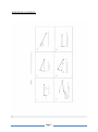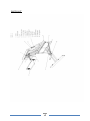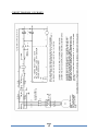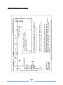
1
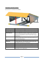
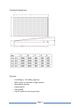
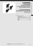
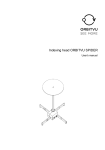
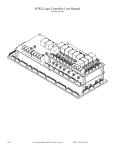
DOCK LEVELLER USER MANUAL TYPE: TELESCOPIC Electro-Hydraulic Hinged Lip Page 1 INDEX TECHINCAL SPECIFICATIONS PAGE 3 OPERATING INSTRUCTIONS PAGE 5 OPERATING SEQUENCE PAGE 7 SAFETY PAGE 8 MAINTENANCE PAGE 10 PARTS LIST PAGE 11 ELECTRICAL CIRCUIT (3 Phase) PAGE 12 ELECTRICAL CIRCUIT (1 Phase) PAGE 13 SERVICE RECORD PAGE 14 Page 2 TECHNICAL SPECIFICATIONS Manufactured in accordance with EN1398 Capacity Platform Width Platform Length Lip Length Platform Material Main Ram Lip Ram Power Pack Control Panel Above/Below Deck Toe Guards Maintenance Prop Fixing Application 6,000Kg dynamic, 10,000Kg static To customer requirement (generally 2000 – 2100mm) To customer requirement (generally 3000mm) 430mm long hinged, cranked or flat with chamfered edge Non-slip durbar plate finished in any RAL colour or galvanised. Leveller platform designed to flex 100mm laterally in each direction to compensate for vehicle tilt while remaining rigid longitudinally Hydraulic single acting with burst valve to prevent platform descending under load, if vehicle inadvertently pulls away, or in the event of hose failure Hydraulic double acting 0.75KW, 380v/50Hz – 3Ph mounted on leveller base frame. Pre-wired for connection to control panel. Rated IP55 – 24v AC with door interlock as standard Dependent on platform length – see table in figure overleaf. Galvanised, telescopic Included All dock levellers can be manufactured to suit pit mounted, suspended or cast in applications. Page 3 Standard dimensions: Options: - 10,000Kg or 15,000Kg capacity RAL colour to customer requirement Alternative lip size Limit switch Galvanised Can be made to suit any pit size Page 4 OPERATING INSTRUCTIONS • Dock levellers should only be used by personnel trained in their operation, and who are authorised to do so. • Dock levellers should only be used for the purpose for which they have been designed, and should never be operated with goods on or in front of the device. • No goods or persons should be left on the leveller when the vehicle has disengaged. • The leveller should only be used for the specific purpose of loading and unloading containers or trucks with the aid of a forklift or pallet truck. • The vehicle should preferably be prevented from moving by the use of chocks or a vehicle restraining device, during the loading and unloading process. • According to EEC standards the maximum permitted gradient is ± 12.5% or approximately ± 7°. Always refer to the appropriate forklift truck operator’s manual, for the maximum safe working gradient. Using The Dock Leveller: Before using the dock leveller make sure that the power supply is switched on. Do not switch the power supply off when the leveller is in use Please comply with the following sequence of events: 1. Ensure that the vehicle is correctly positioned centrally in front of the dock leveller with the rear doors open. 2. Press the control button and keep it depressed until the deck has reached its highest position and the lip is extended. 3. When the control button is released the deck will lower under its own weight. The lip should remain extended. 4. The lip must always provide sufficient support on the loading floor of the vehicle. It should extend no less than 100mm in to the vehicle at all times. Page 5 Returning the deck to its rest position once loading or unloading has been completed: 1. Press the control button and keep it depressed until the deck has raised and the lip fully retracted 2. When the control button is released, the deck will lower under its own weight until the lip has located on the parking blocks Emergency Stop ONLY TO BE USED IN AN EMERGENCY - This button must never be used during loading or unloading, as the deck is unable to follow the up & down movements of the vehicle, which could lead to a potentially dangerous situation, or damage to the leveller. Page 6 OPERATING SEQUENCE Page 7 SAFETY Cross Traffic Support: The leveller lip, when correctly positioned on the stops, will take the weight of all cross traffic to a maximum of 9000Kg Toe Guards: Toe guards on both sides of the leveller protect the operator and other parties. The toe guards are marked in the yellow and black regulation stripes in conformity with EEC regulations. Safety Stop: If a vehicle drives away during loading or unloading & there is a heavy load on the dock leveller, the safety stop will be activated automatically. Once the load has been removed, brief pressure on the control button is sufficient to reset the leveller, which can then be returned to the parked position. The leveller should not be used again until a thorough inspection has been carried out by the supplier or dealer for any deformity or damage. Lateral Tilt: The torsional properties of the leveller deck is such, that the leveller lip can remain in contact with the loading surface of the vehicle with a lateral tilt of approximately 100mm either way. Page 8 Emergency Stop: The emergency stop must only be used in the event of an Emergency. The emergency stop should never be pressed during loading and unloading as the leveller is then unable to follow the up & down movements of the vehicle. Maintenance Supports: Always use the maintenance support during repairs, adjustments, maintenance and cleaning operations that require personnel to go below the deck of the leveller. Power Supply: Always switch off power supply before proceeding with any maintenance or cleaning work. Page 9 MAINTENANCE The user should check for visible signs of damage daily The user should check all functions of the leveller weekly Cleaning & lubrication should be carried out as below Hydraulic system: Check the hoses & unions every six months for leaks or damage Check oil level in the tank every six months, top up as necessary Full oil change is recommended every 2 years Recommended oils for normal applications where the power pack is well sheltered from extremes of temperature are type ISO VG32 viscosity index IP226-150 or better. For applications where the power pack is subject to extremes of temperature use aviation type oils ISO VG26, viscosity index 400 or better Hinges The hinges should be lubricated every six months or as necessary Cleaning The hinges should be cleaned off as necessary The leveller pit should be swept out as necessary & any oil spillage mopped up When carrying out maintenance work the support strut must be in place and the power supply must be turned off Page 10 PARTS LIST Page 11 CIRCUIT DIAGRAM 1 (3 PHASE) Page 12 CIRCUIT DIAGRAM 2 (1 PHASE) Page 13 SERVICE RECORD DATE ENGINEER COMMENTS NOTES Page 14