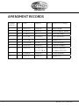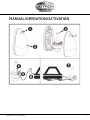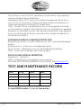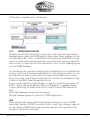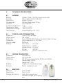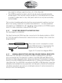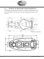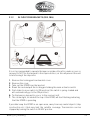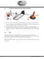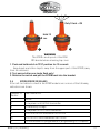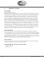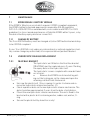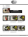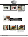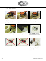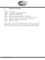
1
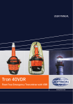
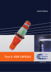
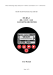
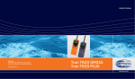
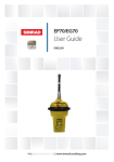
USERS MANUAL
Tron 40S MkII
Tron 40GPS MkII
www.jotron.com
www.jotron.com
Amendment Records
2
Amendment no
By
Date
Page(s)
Vers. Reason for change
1
ES
05.07.07
Total 36
A
New Manual
2
ES
12.04.07
Total 36
B
New company name
3
ES
31.08.07
27
C
Error message
4
ES
31.01.08
21 and 22
D
Man operation
5
ES
10.03.08
2-6, 25, 30
E
Added text
6
ES
29.04.08
6-24
F
Corrected text
7
TH
30.01.09
Total 36
G
Layout changes
8
ES
06.01.10
17, 24-25,
27, 32, 38, 41
H
New FB6 bracket
Included GPS info
9
FIT
25.08.10
Total 42
I
Corrected text
10
FIT
12.07.11
Total 36
J
Added text
82819_UM_40SMkII_J
www.jotron.com
Manual/Operation/Activation
82819_UM_40SMkII_J
3
www.jotron.com
EC Declaration of Conformity, available at www.jotron.com
Abbreviations and definitions
BAUD
Transmission rate unit of measurement for binary coded data (bit per second)
BIT
Short form of Binary Digit. The smallest element of data in a binary-coded value
BPS
Bits Per Second
COSPAS
COsmicheskaya Sistyema Poiska Avariynich Sudov (Space System for the
Search of Vessels in Distress)
EPIRB
Emergency Position Indicating Radio Beacon
GLOBAL POSITIONING SYSTEM (GPS)
The NAVSTAR Global Positioning System, which consists of orbiting satellites, a
network of ground control stations, and user positioning and navigation equipment. The system has 24 satellites plus 3 active spare satellites in six orbital
planes about 20,200 kilometers above the earth.
IEC
International Electro-technical Commission
IMO
International Maritime Organization
IBRD
International 406MHz Beacon Registration Database
ITU
International Telecommunication Union
4
82819_UM_40SMkII_J
www.jotron.com
LED
Light Emitting Diode
LUT
Local User Terminal (Ground Station)
MCA
Marine and Coastguard Agency (UK)
MCC
Mission Control Centre
NOAA
National Oceanic and Atmospheric Administration (USA)
RCC
Rescue Coordination Centre
SARSAT
Search and Rescue Satellite-Aided Tracking System
SBM
Shore Based Maintenance – as required by SOLAS regulation IV/15.9.2 of
SOLAS 1974 as amended with, in accordance with MSC/Circ. 1039 guidelines for
Shore-Based Maintenance (SBM) of Satellite EPIRBs within 5 years if:
Passenger ships (> 12 passengers) and cargo ships (> 300GT) engaged in International voyages, shall perform SBM as follows:
• Latest by the date of the EPIRB label with this text, or the battery. Label,
whichever is first
• When this EPIRB becomes due for SBM in accordance with national requirements.
82819_UM_40SMkII_J
5
www.jotron.com
BATTERY SAFETY DATA SHEET
PRODUCT NAME:
SAFT BATTERIES
TYPE NO.:
LSH14 LIGHT
CELL WEIGHT:
51 g
CHEMICAL SYSTEM:
Lithium/Thionyl chloride
DESIGNED FOR RECHARGE:
No
LITHIUM METAL CONTENT
Below 1 g/cell
HAZARDS IDENTIFICATION
Do not short circuit, recharge, puncture, incinerate, crush, immerse, force discharge or expose to
temperatures above the declared operating temperature range of the product.
Risk of fire or
explosion. The Lithium-Thionyl chloride batteries described in
this Safety Data Sheet are sealed units which are not hazardous when used according to the recommendations of the manufacturer.
Under normal conditions of use, the electrode materials and liquid electrolyte
they contain are not exposed tothe outside, provided the battery integrity is
maintained and seals remain intact. Risk of exposure only in caseof abuse (mechanical, thermal, electrical) which leads to the activation of safety valves and/
or the rupture ofthe battery container. Electrolyte leakage, electrode materials
reaction with moisture/water or battery vent/explosion/fire may follow, depending upon the circumstances.
COMPOSITION & INFORMATION ON INGREDIENTS
Each cell consists of a hermetically sealed metallic container containing a
number of chemicals and materials of construction of which the following could
potentially be hazardous upon release.
- Lithium content - 3.5-5%
FIRST AID MEASURES
Emergency contact: For chemical emergency ONLY (spill, leak, fire, exposure or
accident),
call CHEMTREC at: International: +1-703-527-3887. Within the USA: 1-800424-9300
6
82819_UM_40SMkII_J
www.jotron.com
Inhalation: Remove from exposure, rest and keep warm. In severe cases obtain
medical attention.
Skin contact: Wash off skin thoroughly with water. Remove contaminated clothing and wash
before re-use. In severe cases obtain medical attention.
Eye contact: Irrigate thoroughly with water for at least 15 minutes. Obtain medical attention.
Ingestion: Wash out mouth thoroughly with water and give plenty of water to
drink. Obtain medical attention.
Further treatment: All cases of eye contamination, persistent skin irritation and
casualties who
have swallowed this substance or been affected by breathing its vapours
should be seen by a Doctor.
FIRE FIGHTING MEASURES
CO2 extinguishers or, even preferably, copious quantities of water or waterbased foam, can be used to cool down burning Li- SOCl2 cells and batteries, as
long as the extent of the fire has not progressed to the point that the lithium
metal they contain is exposed (marked by deep red flames). Do not use for this
purpose sand, dry powder or soda ash, graphite powder or fire blankets. Use
only metal (Class D) extinguishers on raw lithium.
Extinguishing media
• Use water or C02 on burning Li-SOCI2 cells or batteries and class D fire extinguishing agent only on raw lithium.
ACCIDENTAL RELEASE MEASURES
Remove personnel from area until fumes dissipate. Do not breathe vapours or
touch liquid with bare hands. If the skin has come into contact with the electrolyte, it should be washed thoroughly with water. Sand or earth should be used to
absorb any exuded material. Seal leaking battery and contaminated absorbent
material in plastic bag and dispose of as Special Waste in accordance with local
regulations.
HANDLING AND STORAGE
Handling - Do not crush, pierce, short (+) and (-) battery terminals with conductive (i.e. metal) goods. Do not directly heat or solder. Do not throw into fire. Do
not mix batteries of different types and brands. Do not mix new and used batteries. Keep batteries in non conductive (i.e. plastic) trays.
Storage - Store in a cool (preferably below 30°C) and ventilated area, away
82819_UM_40SMkII_J
7
www.jotron.com
from moisture, sources of heat, open flames, food and drink. Keep adequate
clearance between walls and batteries.
Temperature above 100°C may result in battery leakage and rupture. Since
short circuit can cause burns, leakage and rupture hazard, keep batteries in
original packaging until use and do not jumble them.
Other - Lithium-Thionyl chloride batteries are not rechargeable and should
not be tentatively charged. Follow Manufacturers recommendations regarding
maximum recommended currents and operating temperature range. Applying
pressure on deforming the battery may lead to disassembly followed by eye,
skin and throat irritation.
EXPOSURE CONTROLS & PERSONAL PROTECTION
Respiratory protection - In all fire situations, use self-contained breathing apparatus
Hand protection - In the event of leakage wear gloves
Eye protection - Safety glasses are recommended during handling
Other - In the event of leakage, wear chemical apron
PHYSICAL AND CHEMICAL PROPERTIES
Appearance - Cylindrical
Odour - If leaking, gives off a pungent corrosive odour
SEE MORE INFO ON MSDS/TRANSPORT DOCUMENTS ON WWW.JOTRON.COM
Test and maintenance record
DATE
N/T/B
SIGN
INSP
N= New EPIRB installed, T= Test, B= New battery
8
82819_UM_40SMkII_J
www.jotron.com
IMPORTANT
TO PERMANENTLY DISABLE EPIRB
The battery module must be
disconnected from the main module
The information in this book has been carefully checked and is believed to be
accurate. However, no responsibility is assumed for inaccuracies.
CAUTION!
This equipment contains CMOS integrated circuits. Observe handling precautions to avoid static discharges which may damage these devices. Jotron AS
reserves the right to make changes without further notice to any products or
modules described herein to improve reliability, function or design. Jotron AS
does not assume any liability arising out of the application or use of the described product.
WARNING / IMPORTANT
Jotron AS is a prime manufacturer of safety equipment designed for rescue of
human lives and their property. For safety equipment to be effective in line with
the design parameters it is important that they are handled, stowed and maintained in compliance with the manufacturers instructions. Jotron AS can not be
held responsible for any damage caused due to incorrect use of the equipment
or breach of laid down procedures or for failure of any specific component or
other parts of the equipment.
The chapter covering battery replacement is added for information only. Jotron
AS does not take any responsibility for improper disassembling/assembling of
the beacon. We strongly recommend all service to be done by authorized Jotron
AS agents. In addition to normal service, Jotron AS agents have the necessary
equipment and education to test the operational functions of the beacon. Nonoriginal maintenance and/or service parts may destroy the equipment function
and performance.
82819_UM_40SMkII_J
9
www.jotron.com
TEST OF RADIO EQUIPMENT
Monthly:
Float-free and manual EPIRBs to be checked using the means provided for
testing on the equipment. Check data for periodical maintenance requirement
for float-free EPIRB.
False alerts transmitted by EPIRB
False alerts are a serious problem for the rescue service. Nearly 90% of EPIRB
initiated distress alerts turn out to be false alarms.
If for any reason, your EPIRB should cause a false alarm, it is most important
that you contact the nearest search and rescue authority and tell them it was a
false alarm. They can then stand down any rescue service (coast radio station
or appropriate CES or RCC). Use any means at your disposal to make contact.
Switch off the distress alarm by de-activating your EPIRB, as soon as possible.
If your beacon is activated in a non-distress situation or a distress situation
which has been resolved and you no longer require assistance, contact the
nearest search and rescue authorities via the most expeditious means available
with the following information:
Beacon ID number (15 character UIN):
Position (At time of activation):
Date of Activation:
Time of Activation (Time zone):
Duration of Activation:
Beacon marke and model:
Vessel Name/lD:
Circumstances/cause (if known):
USA
The United States search and rescue authority is the U.S. Coast Guard. The primary points of contact are:
Pacific Ocean Area
USCG Pacific Area Command Centre
Tel: +1 (510)-437-3701
10
82819_UM_40SMkII_J
www.jotron.com
Atlantic Ocean / Gulf of Mexico Area
USCG Atlantic Area Command Centre
Tel: +1 (757)-398-6231
From Any Location
USCG Headquarters Command Centre
Tel: +1 (800)-323-7233
82819_UM_40SMkII_J
11
www.jotron.com
TABLE OF CONTENTS
1
GENERAL DESCRIPTION
1.1
TRON 40S MkII
1.2
SYSTEM DESCRIPTION
1.2.1 SIGNAL DETECTION
1.2.2 DISTRESS LOCATION DETERMINATION 1.2.3 EPIRB REGISTRATION
14
14
15
15
16
17
2
TECHNICAL SPECIFICATIONS
2.1GENERAL
2.2
COSPAS-SARSAT TRANSMITTER
2.3
HOMING TRANSMITTER
2.4
BRACKETS 18
18
18
18
18
3EPIRB DESCRIPTION
3.1GENERAL
3.1.1
EPIRB MODULE WITH ANTENNA
3.1.2 BATTERY MODULE
3.1.3 EQUATOR RING WITH GASKET
19
19
19
19
19
4INSTALLATION
20
4.1BRACKETS
20
4.1.1
FLOAT FREE BRACKETS FB6, FB5 AND FB4
20
4.1.2 FLOAT FREE BRACKET W/HEATING FBH4
21
4.1.3 MANUAL BRACKET MB5 AND MB4 (older)
21
4.1.4 MOUNTING THE FB6/FB5/MB5/FB4/FBH4/MB4 BRACKETS 22
5OPERATION INSTRUCTIONS
5.1
MANUAL OPERATION 5.1.1
OUT OF BRACKET
5.1.2 IN FLOAT FREE BRACKET (FB4):
5.1.3 IN FLOAT FREE BRACKETS (FB5, FB6)
5.2
AUTOMATIC OPERATION (FB4/FBH4/FB5/FB6) 5.3
TEST 12
23
23
23
24
25
26
26
82819_UM_40SMkII_J
www.jotron.com
6
PERIODICAL CONTROL
28
7
MAINTENANCE 7.1
EPIRB MODULE / BATTERY MODULE
7.1.1
CHANGE OF BATTERY
7.2
HYDROSTATIC RELEASE REPLACEMENT
7.2.1 FB4/FBH4 BRACKET 7.2.2 FB5 BRACKET 7.2.3 FB6 BRACKET 29
29
29
29
29
30
31
8
SPARE PARTS/OPTIONS
33
9
SERVICE PROCEDURE 2011
34
10
SERVICE AGENTS
35
82819_UM_40SMkII_J
13
www.jotron.com
1
GENERAL DESCRIPTION
The Tron 40S MkII and the Tron 40GPS MkII are emergency equipment:
• Tron 40S MkII Cospas-Sarsat emergency EPIRB
• Tron 40GPS MkII Cospas-Sarsat emergency EPIRB incl. GPS receiver
• One of the following brackets:
- FBH4 - Automatic float free bracket v/heating
- FB6 - Automatic float free bracket
• Older brackets:
- FB4 - Automatic float free bracket
- FB5 - Automatic float free bracket
- MB4 - Manual bracket
- MB5 - Manual bracket
The Tron 40S MkII EPIRB is developed to meet all the regulations and rules for
use on ships, vessels and life rafts in the maritime service. Look at the Tron 40S
MkII declaration of conformity document at www.jotron.com to see the regulation and rules used to certify this 406 MHz EPIRB for use in search and rescue
operations at sea.
1.1
TRON 40S MkII
The Tron 40S MkII is buoyant, and is designed to automatically release and activate in case of an emergency where the EPIRB and its bracket is submerged
into the sea. The Tron 40S MkII can also be operated as a manual EPIRB, by
manually releasing it from its bracket and then activating it.
Six different brackets are currently compatible with Tron 40S MkII. MB4 and MB5
are the manual bracket and FB4 and FBH4 is the automatic bracket. FB6/FB5 is
automatic bracket with cover. The automatic bracket is mounted in a free space
outside where the beacon can be released automatically.
The purpose of the Tron 40S MkII is to give a primary alarm to the search
and rescue authorities. The EPIRB gives an immediate alarm when activated,
transmitting the ID of the ship in distress. Care must be taken not to activate
the EPIRB unless in an emergency situation, in such cases the user will be held
responsible. For periodic testing a test function is implemented. During the test
cycle the EPIRB does a self-test on the transmitters and on the battery status.
No emergency signal is transmitted during the self-test. The battery of the
EPIRB will last for at least 48 hours from activation of the EPIRB.
14
82819_UM_40SMkII_J
www.jotron.com
1.2
SYSTEM DESCRIPTION
The Cospas-Sarsat system was introduced in 1982 as a worldwide search and
rescue system with the help of satellites covering the earth’s surface. Since the
introduction of the system more than 28000 persons have been rescued by
the Cospas-Sarsat system (2009). Currently the system consists of 5 functional
satellites in a polar orbit constellation, these satellites cover the entire earth’s
surface and receive the emergency signal from the 406 MHz transmitter within
the Tron 40S MkII, more polar orbiting satellites will be available in the future,
giving a faster location and rescue time.
In addition several geostationary satellites are equipped with a 406 MHz transponder, these satellites are not able to locate the Tron 40S MkII but will give an
early warning to the rescue forces, minimising the time from an emergency occurs till the rescue forces are at the site.
Each emergency EPIRB in the system is programmed with its own unique code,
therefore it is vital that the ships data that is given to the dealer you obtained
your Tron 40S MkII, is correct. It is also important that your EPIRB is registered
in the database for each country. This database is normally located in the same
country that the ship is registered.
1.2.1
SIGNAL DETECTION
When the Tron 40S MkII is activated (manually or automatically)
it transmits on the frequencies
121.5 MHz and 406.037 MHz. An
analogue signal is emitted on
121.5 MHz and a digital signal is
transmitted on 406.037 MHz.
After the Tron 40S MkII is activated, the next passing satellite will
detect the transmitted signal and
relay it to an antenna at a ground
station, called an LUT.
When the EPIRB transmits 406 message, it is received by low orbit satellites
(800) km) and if the position is between 70° north and 70° south, also by geostationary satellites (36000 km). The low orbit satellites which are polar orbiting
types will store the distress message and forward to nearest LUT when it passes.
82819_UM_40SMkII_J
15
www.jotron.com
This gives the Cospas-Sarsat system a truly global coverage.
Once the signal is received by the LUT, it is processed for location and sent to a
Mission Control Centre (MCC). The MCC sorts the alert data according to geographic search and rescue regions and distributes the information to the appropriate Rescue Co-ordination Centre (RCC), or if outside the national search
and rescue area, to the appropriate MCC that covers the area where the distress
signal was detected. The RCC in turn takes the necessary action to initiate
search and rescue activities.
The International Cospas-Sarsat System ceased satellite processing of
121.5/243 MHz beacons from 1 February 2009. From that date only 406 MHz
beacons will be detected by the Cospas-Sarsat satellite system. This affects all
maritime beacons (EPIRBs), all aviation beacons (ELTs) and all personal beacons (PLBs). 121.5/243MHz is now only used for homing.
1.2.2
DISTRESS LOCATION DETERMINATION
The location of the distress signal is determined by taking measurements of the doppler shift of the EPIRB frequency when the satellite first approach and then pass
the EPIRB.
The actual frequency is heard at the time of closest approach (TCA). Knowing the position of the satellite and
using the received doppler signal information, it is possible to determine the location of the Tron 40S MkII from
the satellite at the TCA. At the LUT, actually two positions
are calculated. One is the actual position (A) and the other is the mirror image (B) position. A second satellite pass confirms the correct
location (A). With the 406 system the real solution can be determined on the
first pass with a reliability of nearly 90% and down to an accuracy of less than 5
km (3.1 miles).
1.2.2.1 GPS ADVANTAGE
Tron 40S MkII has been designed to operate with the Cospas-Sarsat system
and will enhance further the lifesaving capabilities of conventional beacons.
Please see below comparison between Tron 40S MkII and Tron 40GPS MkII depending on detection by polar orbiting or geostationary satellites.
16
82819_UM_40SMkII_J
www.jotron.com
GPS position is updated every 20 minutes.
1.2.3
EPIRB REGISTRATION
Normally the MCC will contact the vessel or the contact person registered in a
shipping register and/or an EPIRB register (Ships owner, family member etc.) before alerting the RCC. This is to determine if the alarm from the EPIRB for some
reason is a false alarm, and an expensive rescue operation can be avoided. Because of this it is important that the ships data is correct in the shipping register
or in the EPIRB database.
You should register your beacon with the national authority associated with the
country code in the hexadecimal identification (15 Hex ID) of your beacon. You
can register your beacon online with the Cospas-Sarsat IBRD if your country
does not provide a registration facility and your country has allowed direct registration in the IBRD: www.406registration.com
If your country operates a national beacon registry, consult the document C/S
S.007 ”Cospas-Sarsat Handbook of Beacon Regulations” available at www.
Cospas-Sarsat.org to obtain the point of contact. Some EPIRB registration
links:
USA: http://www.beaconregistration.noaa.gov
UK: http://www.mcga.gov.uk (search for ”EPIRB registration”)
USA
Vessel owners shall advise NOAA in writing upon change of vessel or EPIRB
ownership. Transfer of EPIRB to another vessel, or any other change in registration information, NOAA will provide registrants with proof of registration and
change of registration postcards.
82819_UM_40SMkII_J
17
www.jotron.com
2
TECHNICAL SPECIFICATIONS
2.1
GENERAL
Battery:
Housing:
Dimensions:
Max diameter: Materials:
Compass safe distance:
Temperature range:
Temperature storage:
Operating life:
Lithium , Metal, 7,2v/7Ah, 5 years service life
Glass reinforced polycarbonate
Height: 379 mm
180 mm, Weight app:. 2.0 kg
Polycarbonate.
1.5 m
-20°C to + 55°C
-40°C to + 55°C
Minimum 48 hours at -20°C
2.2
COSPAS-SARSAT TRANSMITTER
Frequency:
406.037 MHz ± 2 ppm
Output power:
5W ± 2 dB
Protocols:
Tron 40S/GPS MkII: Maritime, Serialized, Radio Call sign
Modulation:
Phase modulation 1,1 ± 0.1 rad
Data encoding:
Bi Phase L
Stability:
Short term:
≤ 2 x10e-9
Medium term: ≤ 10e-9
Residual noise: ≤ 3 x10e-9
Bit rate: 400 b/s
Antenna: Built in, omnidirectonal.
2.3
HOMING TRANSMITTER
Frequency:
121.500 MHz
Output power:
Up to 100 mW
Modulation:
A9, AM sweep tone between 300Hz and 1600Hz. Sweep range: 700 Hz.
Sweep rate: 2.5 Hz.
FB6
Stability:
10 ppm over temperature range.
Antenna: Built in, omni directional.
2.4
BRACKETS
Materials:
Luran S/ ABS
Dimensions: See ch. 4.1.4
Release mechanism: Hydrostatic release unit
Hammar H20 with Jotron special bolt
18
82819_UM_40SMkII_J
www.jotron.com
3
EPIRB DESCRIPTION
3.1
GENERAL
The Tron 40S MkII consists of upper and lower house mounted together with an
equator ring with gasket and locking pin.
Tron 40S MkII may be split into the following main parts:
• EPIRB module with antenna
• Battery module
• Equator ring with gasket
3.1.1
EPIRB MODULE WITH ANTENNA
The EPIRB module consists of two printed circuit boards, which are mounted in
the upper housing:
• The main board with main switch.
• Antenna board (121.5 / 406 MHz) with indicator / flash LED
3.1.2
BATTERY MODULE
The Battery module supplies the EPIRB module with 7.2 VDC power to keep the
EPIRB transmitters active for 48 hours when activated, and for test sequences.
The battery module is attached inside the lower house. The housing is made of
glass reinforced polycarbonate. In the lower part of the housing there is one
reed contact, which is activated by a magnet in the release mechanism. This
is the safety switch, which prevents the seawater contacts from activating the
beacon while placed in the mounting bracket. There is a internal brass weight,
which gives stability while floating.
The seawater contacts are also mounted in the battery module, and are connected to the electronic unit via the battery connector.
The batteries are mounted in a plastic battery holder.
3.1.3
EQUATOR RING WITH GASKET
The two parts of the housing are held together by the equator ring, and is locked
with a U-shaped bolt of stainless steel and a split pin. Between the two halves of
the housing there is a gasket made of neoprene.
82819_UM_40SMkII_J
19
www.jotron.com
4
INSTALLATION
4.1
BRACKETS
2 different brackets are currently available for the Tron 40S MkII. FB6 and FBH4
are the automatic brackets. The automatic brackets are mounted in a free
space outside where the beacon can be released automatically. FB6 is delivered
with protective cover. The older brackets; FB4, FB5, MB4 and MB5 are still compatible with Tron 40S MkII.
4.1.1
FLOAT FREE BRACKETS FB6, FB5 AND FB4
WARNING:
DO NOT INSTALL THE EPIRB NEAR STRONG
MAGNETIC FIELDS THAT COULD ACTIVATE THE BEACON
When the Tron 40S/GPS is mounted in the float-free bracket, FB6, it will operate as an automatic float free unit. The satellite float-free EPIRB should be located/installed so that the following requirements are fulfilled:
• The EPIRB should, with greatest possible probability, float-free and avoid be-
20
82819_UM_40SMkII_J
www.jotron.com
ing caught in railings, superstructure, etc., if the ship sinks.
• The EPIRB should be located so that it may be easily released manually
and brought to the survival craft by one person. It should therefore not be
located in a radar mast or any other places which can only be reached by
vertical ladder.
The location should be well protected from environmental conditions such as
direct sea-spray, chemicals, oil, exhaust and vibrations. - see more detailed
information in ”COMSAR/Circ.32” regarding ”Harmonization of GMDSS requirements for radio intallations onboard SOLAS ships”
4.1.2
FLOAT FREE BRACKET W/HEATING FBH4
See next page for installation.
The float free bracket FBH4 must be connected to the fixed installation (230V
AC, 10A) through the thermostat connection box according to the connection
diagram below.
HEATING ELEMENT
230 V AC, 10 A
Thermostat
The actual current consumption is maximum 30W, but power is turned off by the
thermostat over approx. 0°C (32°F)
Figure 4.1.2 Connection diagram FBH4
4.1.3
MANUAL BRACKET MB5 AND MB4 (older manual brackets)
When the Tron 40S MkII is mounted in the MB5 or MB4 bracket, it will operate as a manual unit. This bracket is similar to the FB6, FB5 and FB4 bracket
but does not have the hydrostatic release mechanism. This bracket is typically
used to store the EPIRB inside the wheelhouse or other protected areas of the
ship. When the Tron 40S MkII is mounted in the MB5 or MB4 bracket, it must be
manually removed before any operation can take place, therefore the bracket
should be mounted in an easily accessible place where it can be removed in a
hurry in case of an emergency.
82819_UM_40SMkII_J
21
www.jotron.com
4.1.4
MOUNTING THE FB6/FB5/MB5/FB4/FBH4/MB4 BRACKETS
The bracket is mounted with 4x6mm bolts according to the drawing. Use the
bolts supplied with the bracket. The bracket could be mounted in either a vertical or horizontal position, whichever is the best regarding maintenance and
operation.
FB4
FB6
22
82819_UM_40SMkII_J
www.jotron.com
5
OPERATION INSTRUCTIONS
WARNING
- USE ONLY DURING SITUATIONS OF GRAVE AND IMMINENT DANGER
- REPLACE THE BATTERY AFTER THE SATELLITE EPIRB IS OPERATED
FOR ANY PURPOSE OTHER THAN A TEST
The Tron 40S MkII is designed to be operated either manually or automatically.
The EPIRB is always armed, that is the EPIRB will automatically start to transmit
when the EPIRB is out of the bracket and deployed into water. In the lower part of
the EPIRB there is an automatic safety switch. This switch prevents the seawater
contacts from operating the EPIRB (caused by ice, sea-spray etc.) as long as the
EPIRB is placed in its bracket. See chapter 6.4 Error codes.
5.1
MANUAL OPERATION
For operation of the beacon in the bracket please follow instructions 1 to 3.
5.1.1
OUT OF BRACKET
1
2
3
WARNING
USE ONLY DURING SITUATIONS
OF GRAVE AND IMMINENT DANGER
Regarding the 3 pictures above, follow instructions from 3-6 on page 23.
82819_UM_40SMkII_J
23
www.jotron.com
5.1.2
IN FLOAT FREE BRACKET (FB4):
It is not recommended to operate the beacon inside a life raft or under a cover or
canopy. Do NOT tie the lanyard to the ship in distress, as this will prevent the unit
to functioning if the ship sinks.
Option 1:
Tron 40S MkII may be activated inside the FB4 bracket. If this is desirable, follow
instructions on last page, chapter 5.1.1, pictures 1-3
Option 2:
• Pull out the locking pin on the clamp and open the retaining rod that
holds the EPIRB
• Remove EPIRB from bracket
• Break the seal and pull the locking pin holding the main activator switch
• Push slider to move switch to ON position (the switch is spring-loaded
and will automatically go to the ON position)
• Tie the beacon lanyard to you or to the survival craft
• The strobe light, located at the top of the EPIRB, will start flashing indicating that the EPIRB is operating
If possible keep the EPIRB in an open area, away from any metal objects (ship
construction etc.) that may limit the satellite coverage. Transmission can be
stopped by turning the switch to READY position.
1
24
2
82819_UM_40SMkII_J
www.jotron.com
5.1.3
IN FLOAT FREE BRACKETS (FB5, FB6)
It is not recommended to operate the beacon inside a life raft or under a cover or
canopy. Do NOT tie the lanyard to the ship in distress, as this will prevent the unit
to functioning if the ship sinks.
1.
2.
3.
4.
5.
Remove the locking pin from bracket cover
Remove the cover
Take out the EPIRB from the bracket
Break the seal and pull the locking pin holding the main activator switch
Push slider to move switch to ON position (the switch is spring-loaded and
will automatically go to the ON position)
6. Tie the beacon lanyard to you or to the survival craft
7. The strobe light, located at the top of the EPIRB, will start flashing indicating
that the EPIRB is operating
If possible keep the EPIRB in an open area, away from any metal objects (ship
construction etc.) that may limit the satellite coverage. Transmission can be
stopped by turning the switch to READY position.
82819_UM_40SMkII_J
25
www.jotron.com
5.2
AUTOMATIC OPERATION (FB4/FBH4/FB5/FB6)
1. The Tron 40S MkII will automatically release from the bracket, float to the
surface and start to transmit when the EPIRB, in its bracket is deployed into
water at a depth of app. 2-4 meters (6 - 13 feet).
2. Transmission will continue until the EPIRB is lifted out of the water, and
dried off. The transmission can also be stopped by placing the EPIRB in the
bracket. (If switch is in ”READY” position, otherwise move switch to this position).
5.3
TEST
To perform the self-test, the EPIRB has to be removed from the bracket.
FB4 bracket: Remove EPIRB from the bracket by pulling out the locking pin on
the clamp and open the retaining rod that holds the beacon.
FB6/FB5 bracket: Release top cover by removing the locking split pin and special washer.
26
82819_UM_40SMkII_J
www.jotron.com
Only 1 flash = OK
Hold 15
sec.
1
2
WARNING
The EPIRB can drop out of the FB6/
FB5 bracket when releasing top cover
1. Push and hold switch in TEST position for 15 seconds
Keep hands and other objects away from the upper part of the EPIRB (away
from the antenna).
2. Test passed after one single flash only!
3. Release the switch and put the EPIRB back into the bracket
5.4EPIRB ERROR MESSAGES
If the self-test detects a fault in the EPIRB module one or more of the following
indications are shown:
Number of
flashes:
Fault indication:
1
NONE
2
Low power on 406 MHz transmitter
3
Low battery voltage
4
Low power on 121.5 MHz transmitter
5
PLL on 406 MHz transmitter out of lock
6
PLL on 121.5 MHz transmitter out of lock
7
EPIRB module not programmed or programming not complete
82819_UM_40SMkII_J
27
www.jotron.com
6
PERIODICAL CONTROL
Every Month:
Perform EPIRB self-test
What the self-test actually does is to send out a short test signal on 121,5 and
406,037MHz, testing the output of the transmitter. While transmitting the test
signal, the battery voltage, output power and phase lock is tested. During the
test of the 406MHz transmitter a test message is transmitted, this test message is coded with a special synchronization code and will not be recognized
as real alert by the COSPAS/SARSAT satellites. Carry out visual inspection for
defects on both the Tron 40S MkII and Bracket. The Tron 40S MkII should be
easily removed and replaced in the Bracket. Make sure that the Tron 40S MkII
and Bracket is not painted or otherwise covered with chemicals, oil, etc. Check
the expiry date of the EPIRB Battery and the Hydrostatic Release Mechanism.
Check the presence of a firmly attached lanyard in good condition and that it is
neatly stowed and is not tied to the vessel or the mounting bracket. If the Tron
40S MkII is the main EPIRB on board, these rules must be followed.
Every 12th month:
If the Tron 40S MkII is the main EPIRB on board and the ship falls under the
SOLAS regulations, these rules must be followed: Perform extended annual test
according to IMO’s MSC/Circ.1040 (Annual testing of 406 MHz satellite EPIRBs)
as required by SOLAS IV/15.9.This test can be carried out by one of Jotron AS
authorized representatives or any other service provider in possession of a Tron
UNIDEC or any other Cospas/Sarsat EPIRB tester/decoder.
Every 2nd Year:
Hydrostatic Release Mechanism including Plastic Bolt on the Float Free Brackets must be replaced. (Check expiry date on label).
Every 5th Year: (Or 4th year in some countries)
• Battery change
• SBM (see 7.1)
28
82819_UM_40SMkII_J
www.jotron.com
7
MAINTENANCE
7.1
EPIRB MODULE / BATTERY MODULE
If the EPIRB is fitted on a vessel which requires GMDSS compliant equipment,
the EPIRB shall be tested and approved as required by SOLAS regulation
IV/15.9.2 of SOLAS 1974 as amended with, in accordance with MSC/Circ.1039
guidelines for shore-based maintenance of Satellite EPIRBs within 5 years, or by
the date of battery expiry, whichever comes first.
7.1.1
CHANGE OF BATTERY
The Tron 40S MkII battery must be changed at Jotron SBM authorized workshop
to be GMDSS compliant.
If your Tron 40S MkII is not under any international or national regulations, battery can be change by authorized Jotron representatives/partners/dealers.
7.2
HYDROSTATIC RELEASE REPLACEMENT
7.2.1
•
•
•
•
FB4/FBH4 BRACKET
The hydrostatic unit fitted on the float free bracket
[FB4/FBH4] must be replaced every 2 years. Marking
the expiry date on the hydrostatic unit.
The hydrostatic comes complete with a new bolt and
accessories.
•
Remove the EPIRB from its bracket by pulling out the locking pin on the clamp and open the
retaining rod that holds the beacon.
Unscrew the plastic bolt (1) by screwing it counter clockwise and remove the hydrostatic release mechanism (2).
Check expiration date on the new hydrostatic release mechanism. The
date should be approximately 2 years from the date of installation.
Mount the new hydrostatic release mechanism. The unit is fixed to the
bracket with a plastic bolt containing washer, rubber seal, washer, Oring.
Secure the plastic bolt by hand force only!
82819_UM_40SMkII_J
29
www.jotron.com
7.2.2
FB5 BRACKET
7.2.2.1
DISASSEMBLY
WARNING
The EPIRB can drop out of the FB6/FB5
bracket when releasing top cover
Remove the locking pin from
bracket cover
- Remove cover
- Remove EPIRB
Press down the spring-loaded
bracket plate and remove the
hydrostatic unit by sliding it
out of its locking slot (b).
Carefully release the spring
loaded stainless bracket plate
and remove the Hydrostatic
Release Unit (HRU).
Press down the Bracket plate
and make sure the stainless
washer goes through the hole
in the bracket back cover.
Slide the HRU UPWARDS to
the end of the ”Keyhole”.
7.2.2.2 ASSEMBLY
Insert the new HRU into the
spring-loaded bracket plate’s
”key hole” as seen on picture.
30
82819_UM_40SMkII_J
www.jotron.com
Shows CORRECT mounting
(photo from back of bracket)
7.2.3
Shows INCORRECT mounting
(photo from back of bracket)
Reinstall the EPIRB and the
top cover and mount washer
and locking pin. Note: Make
sure that top cover is in lock
at bottom.
FB6 BRACKET
WARNING
The EPIRB can drop out of the FB6/FB5
bracket when releasing top cover
Remove the locking pin from
bracket cover
- Remove cover
- Remove EPIRB
82819_UM_40SMkII_J
Slide the HRU UPWARDS
to the opposite side of the
”Keyhole”.
Carefully release the spring
loaded bracket plate and twist
the Hydrostatic Release Unit
(HRU) as seen on the picture
to release it.
31
www.jotron.com
7.2.3.1
DISASSEMBLY
Insert the new HRU into the
spring-loaded bracket plate’s
”key hole” as seen on picture
by twisting it.
Press the HRU and bracket
plate down and make sure
that the stainless washer
goes through the hole in the
bracket back cover
Slide the HRU DOWNWARDS
to the end of the ”Keyhole”
and make sure it goes into
correct position.
Shows correct positioned HRU
in contact with ”end stop”
Detail of washer currently sealed seen through ”key hole”.
Shows CORRECT mounting
(photo from back of bracket)
7.2.3.2 ASSEMBLY
Shows INCORRECT mounting (photo from back of bracket)
32
Reinstall the EPIRB and the
top cover and mount washer
and locking pin. Note: Make
sure that top cover is in lock
at bottom.
82819_UM_40SMkII_J
www.jotron.com
8
SPARE PARTS/OPTIONS
82819
99897
83051
83056
80414
85216
97777
97821
98204
User Manual
Programming (Country, Call Sign, MMSI)
Tron 40S MkII, electronic unit
Battery kit, Tron 40S/GPS MkII
Hydrostatic release mechanism kit for FB5/FB6
FB6 Float-free bracket, automatic release, w/protective cover
FBH4 Float-free brakcet, automatic release, with heating
Hydrostatic release mechanism for FB4
Release kit for FB4
NOTE: Keep the original satellite EPIRB packaging, since it may be needed if the
EPIRB has to be shipped for servicing. UN requirements for shipping some batteries as hazardous goods require certain packaging standards and labelling.
82819_UM_40SMkII_J
33
www.jotron.com
9
SERVICE PROCEDURE 2011
WARRANTY CLAIM
Warranty claims are valid until 5 years from delivery from our warehouse.
The warranty is valid as long as service and battery replacement are carried out
by authorized Jotron distributors or agents.
All products are warranted against workmanship and factory defect, in material.
Any warranty claims must be sent to Jotron, in writing.
Jotron reserve the right to decide whether a defective unit is within warranty
terms and conditions.
If Jotron make a decision of repairing a defective product, a written description
of the claim and a Jotron RMA number, should follow the unit when returning it
back to Jotron’s factory.
Please be noted that un-protective electronics board MUST be packed in antistatic bag, before returning to Jotron’s factory.
Any costs related to transportation and/or workmanship linked up to the return
of the product being repaired shall be covered by the customer.
Jotron’s obligations during warranty replacement;
• Replace defective unit, including any programming
• Delivery terms: DAP Incoterms 2010 by regular freight to “Place” (Airport)
Service agent’s obligations during warranty claims:
• Supply replacement unit from own stock if available
• If agreed, return defective unit to Jotron
• Electronic units must be shipped in antistatic bags or covered with Jotron’s
plastic cover
SERVICE – NOT WARRANTY CLAIM
Service, such as testing, installation, programming, replacement, marking and
battery exchange are provided by an authorized Jotron service agent.
Jotron do not meet the cost for services mentioned above. Distributor or service
agent should stock the most commonly needed spare parts.
34
82819_UM_40SMkII_J
www.jotron.com
10
SERVICE AGENTS
Please look at www.jotron.com for Marine Service Agents.
Jotron Group subsidiary companies:
Jotron UK Ltd.
Crosland Park
Cramlington
NE23 1LA
United Kingdom
Tel
+44 1670 712000
Fax
+44 1670 590265
E-mail: [email protected]
Jotron Asia Pte. Ltd.
Changi Logistics Center
19 Loyang Way #04-26
Singapore 508724
Tel
+65 65426350
Fax
+65 65429415
E-mail: [email protected]
Jotron USA, Inc.
10645 Richmond Avenue, Suite 170
Houston, TX 77042
USA
Tel
+1 713 268 1061
Fax
+1 713 268 1062
E-mail: [email protected]
82819_UM_40SMkII_J
35
www.jotron.com
CONTACT INFORMATION
Jotron AS (HQ)
Jotron AS
Jotron AS
Jotron UK Ltd.
Jotron Asia Pte. Ltd.
Jotron USA, Inc.
P.O.Box 54
3281 Tjodalyng
Norway
Tel: +47 33 13 97 00
Fax: +47 33 12 67 80
[email protected]
Crosland Park
Cramlington
NE23 1LA
United Kingdom
Tel: +44 (0) 1670 712000
Fax: +44 (0) 1670 590265
[email protected]
36
P.O.Box 274
3192 Horten
Norway
Tel: +47 33 08 35 00
Fax: +47 33 08 35 01
[email protected]
19 Loyang Way
Changi Logistics Centre
Rear Office Block 04-26
Singapore 508724
Tel: +65 65426350
Fax: +65 65429415
[email protected]
Dølasletta 7
3408 Tranby
Norway
Tel: +47 32 84 53 87
Fax: +47 32 84 55 30
[email protected]
10645 Richmond Avenue
Suite 170
Houston, TX 77042
USA
Tel: +1 713 268 1061
Fax: +1 713 268 1062
[email protected]
82819_UM_40SMkII_J
v.A