1
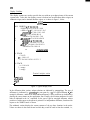
December 19 75
Stanford Artificial Intelligence Laboratory
Memo AIM-274
Computer Science Department
Report No. STAN-C% 7 5-53 6
INTERACTIVE GENERATION OF
OBJECT MODELS WITH A MANIPULATOR
David Il. Grossman and Russell H. Taylor
Research
sponsored
by
Nat ional Science Foundation
and
Advanced Research Projects Agency
ARPA Order No. 2494
COMPUTER SCIENCE DEPARTMENT
Stanford University
Stanford Artificial Intelligence Laboratory
Memo AIM-274
Computer Science Department
Report No. STAN-B-75-536
December 1975
..
INTERACTIVE GENERATION OF
OBJECT MODELS WITH A MANIPULATOR
bY
David D. Grossman and Russell H. Taylor
ABSTRACT
‘Manipulator programs in a high level language consist of manipulation procedures and object
model declarations. As higher level languages are developed, the procedures will shrink while
the declarations will grow. This trend makes it desirable to develop means for automating the
generation of these declarations. A system is proposed which would permit users to spctify
certain ob&ct models interactively, using the manipulator itself as a measuring tool in three ’
dimensions. A preliminary version of the system has been tested.
*..’
7 ’
Davtd Grossman’s permanent address is: Computer Science Department, IBM T.J. Watson
Research Center, P-0. Box 218, Yorktown Heights, New York 10598
This research was supported by the National Science Foundation under Contract NSF G/42906
and the Advanced Research Projects Ageng of the Department of Defense under Cantract DAHC
15-73-C-0435 . The views and conclusions contained in this document are those of the author(s) and
should not be interpreted as necessarily representing the oflcial polfcies, either expressed or
implied, of Stanford University, NSF, ARPA, or the V. S. Government.
Reproduced in the U.S.A. Available from the National Technical !nformation Service, Springtfeki,
Virginia 22151.
INTRODUCTION
Manipulator Languages and Object Models
-.
The important problem areas for current research on manipulators are function, ease of
programming, and speed and reliability of execution. The domain of function is concerned
with whether or not certain tasks are technically feasible, without regard to economic issues.
For the real world environment of industrial assembly, function was demonstated by
assembling a water pump with the Stanford arm in 1973 and by similar experiments at
other laboratories.
Since 1973, the main thrust of the Stanford effort has been directed at ease of programming,
since this is a problem well suited to the skills and interests of the people here. The
approach taken was to design a new high level language called AL in which assembly
programs would be much simpler to code than in any previously existing manipulator
language. The complete AL system is currently beginning to operate.
.
Most other laboratories and companies have chosen to pursue a teaching by doing approach
to manipulator programming instead of developing high level languages. There is good
reason to believe that in the long run the greater generality offered by a system
incorporating formal languages will outweigh the short run ease of programming by guiding.
The ultimate goal of research on high level manipulator languages is a language in which
very few statements are needed to describe a highly complex assembly. For an object with N
parts, perhaps a realistic goal would be to have a language in which the assembly can be
described in about N statements.
e
In view of this goal, the level of manipulator languages is best measured by the’ number of
source statements required, not by the richness of their computer science content. Based on
this criterion, AL is the highest level manipulator language ever developed, in spite of the
fact that it lacks arrays, lists, string variables, formatted I/O, and so forth.
It is instructive to extrapolate from AL to an absurd ultimate high level language. In this
ultimate language, a program for assembling 1000 water pumps might have this form:
.
DECLARE WATER-PUMP etc;
MAKE,PLAN(WATER,PUMP,ASSEMBLY,PLAN);
EXECUTE,PLAN(ASSEMBLY-PLAN,lOOO);
Such a program presumes that all the relevant artificial intelligence problems have been
solved and embodied in MAKE-PLAN and all the manipulation problems have been solved
and embodied in EXECUTE-PLAN. The important observation to make with respect to
this absurd example is that as far as the user of such a language is concerned, all the effort
of writing the program would be in expanding the “etc” in the first line.
The expansion of the “etc” constitutes the world model used by MAKE-PLAN. The world
model would include the specification of mechanical parts, component hierarchies, affixment
relationships, geometric shapes, Cartesian transformations between features, material
’
’
PI
properties, and so forth. It is clear that the declaration of such a detailed world model would
be a lengthy process, possibly requiring hundreds of lines of text.
The development of high level manipulation languages, therefore, will shift the problem
from writing procedures to writing declarations. Already in AL a sufficiently high level has
been reached that this new problem is becoming significant.
A rough measure of the importance of de;F;ations as compared to procedures may be
obtained by looking at sample AL programs and taking the ratio of lines of code in the
two categories. Neglecting comments, three low level AL examples have declaration to
procedure ratios of 12, 16, and 1:3. A “very high level” AL example, however, has a
declaration to procedure ratio of 61. Actually, the importance of declarations is even greater
than these ratios would indicate, since the declarative statements tend to be far more difficult
to code than the procedural statements. Even at the lowest level of AL, appreciable time can
be spent in defining simple models for the initial locations of objects and their affixment
structure.
Since the motivation behind high level manipulator languages is ease of programming, and
since these languages are shifting the problem from procedures to declarations, it is natural
to consider means for simplifying the generation of these declarations. This report proposes
in some detail a prototype system which would semi-automate the process of specifying a
large class of AL declarations. It is believed that a system of this type would be general
enough to be applicable to other high level manipulation languages also.
Attributes of AL World Models
a
The AL languag;lfas evolved considerably during implementation over the past year, and
has become somewhat obsolete. Nevertheless, in order to keep the
the AL Manual
discussion on a concrete footing, it will be assumed that AL declarations take exactly the
form shown in the AL Manual, and it will also be assumed that the reader is familiar with
this manual.
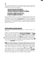
A section of the “very high level” AL example is reproduced below:
FRAME beam, bracket, bolt;
FRAME bracket-bore, beam-bore;
FRAME bolt-grasp, bracket-handle;
ASSERT FORM (TYPE, beam, object);
ASSERT FORM (GEOMED, beam, “beam.B3D”);
ASSERT FORM (SUBPART, beam, beam-bore);
AFFIX beam-bore TO beam RIGIDLY
AT TRANS(ROT(Y,9O),VECTOR(O,l.5,6));
ASSERT FORM (TYPE, bracket, object);
ASSERT FORM (CEOMED, bracket, “BRACKBSD”);
ASSERT FORM (SUBPART, bracket, bracket-bore);
t41
ASSERT FORM (SUBPART, bracket, bracket-handle);
AFFIX bracket-bore TO bracket RIGIDLY
AT TRANS(ROT(X, l$O),VECTOR(ti. l2,O));
AFFIX bracket-handle TO bracket RIGIDLY
AT TRANS(ROT(X, l$O),NILVEC);
ASSERT FORM (TYPE, bolt, SHAFT); -ASSERT FORM (DIAMETER, bolt, 0.5&M);
ASSERT FORM (TOP-END, bolt, head-typel);
ASSERT FORM (BOTTOM-END, bolt, tip-typel);
ASSERT FORM (TYPE, tip-type], FLAT-END);
. . .
bracket c FRAME(NILROT,VECTOR(20,40,0)~
beam c FRAME(NILROT,VECTOR( 10,60,0));
bolt c FRAME(ROT(Y,180),VECTOR(30,50,5));
All of the above statements are considered to be declarations of the world model since they
occur prior to the first. .motion of the manipulator.
.
The method of automating declarations to be described here is inappropriate for specifying
information about the geometric shape of objects. Therefore, all statements which relate to
geometric shape either in the form of GEOMED files”’ or in the form of generic parts such
as SHAFT will be omitted from further consideration.
Fortunately, it is possible to write fairly high level AL programs which do not need shape
information, although in an ultimate high level language, of course, geometric shape
declarations will ‘have to be provided. The eventual automation of shape declaration will
some day come about through advanced interactive graphics and vision syste-. It is :.
important to realize, however, that while this major problem area is being bypassed ‘in thi$
discussion, the problems which remain are still substantial, and their practical solution would
make it significantly easier to code AL programs.
.
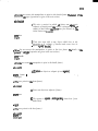
The remaining statements may be rearranged according to their function in the following
manner:
FRAME beam, bracket, bolt;
FRAME bracket-bore, beam-bore;
FRAME bolt-grasp, bracket-handle;
ASSERT FORM (TYPE, beam, object);
ASSERT FORM (TYPE, bracket, object);
ASSERT FORM (SUBPART, beam, beam-bore);
ASSERT FORM (SUBPART, bracket, bracket-bore);
ASSERT FORM (SUBPART, bracket, bracket-handle);
AFFIX beam-bore TO beam RIGIDLY
AT TRANS(ROT(Y ,90),VECTOR(O,1.5,6));
AFFIX bracket-bore TO bracket RIGIDLY
-
AT TRANS(ROT(X, 180),VECTOR(5.1,2,0));
AFFIX bracket-handle TO bracket RIGIDLY
AT TRANS(ROT(X,180),NILVEC);
bracket t FRAME(NILROT,VECTOR(20,40,0));
beam t FRAME(NILROT,VECTOR( 10,60,0));
bolt c FRAME(ROT(Y, 180),VECTOR(30,50,5));
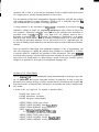
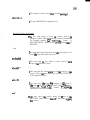
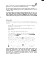
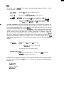
The net effect of these statements is to describe a tree in which the nodes represent physical
objects and the arcs are relationships between them. The root of the tree is an implicit ob&t
which may be called “world”, and all objects which are not subparts of anything else me
subparts of world. The subpart hierarchy is shown in graphical form below:
+--------------------------------------------------~------+
UORLO
I
+---------+
+------------------------------*
I
+----..----a+
BRACKET
I I BOLT I
I BEAfl I I
+---------+ +------------------------------+ +------w--w+
I
I
I
I
I
I
I
I
I
I
I
I
I
I
I
I
+-w-s-----+
4
+------------+
+--w--w--------+
+-.---b-B--+
lBERtlJOREl
(BRFICKETJOREJ
(BRflCKET,HANDLE(
IBOLT,CRRSPJ
+-e-----m-+
+-------w----+
+-----.--------+
+------..---+
The arcs have the implication of subpart or, equivalently, of subfeature. Each arc also must
contain information concerning the relative transformation between the Cartesian frame of
the parent and that of the son. For those arcs which emanate from world, these
transformations are AL frames, while for all other arcs they are AL transet. Finally, each WC
must specify whether the relationship is rigid, non-rigid, or independent.
The principal difficulty for the programmer in specifying this tree lies in the symbolic
definition of the frames and transes:
FRAME(NILROT,VECTOR(20,40,0))
FRAME(NILROT,VECTOR( 10,60,0))
FRAME(ROT(Y, 180),VECTOR(30,50,5))
G
TRANS(ROT(Y,SO),VECTOR(O,1.5,6))
TRANS(ROT(X,180),VECTOR(5.1,2,0))
TRANS(ROT(X, 180),NILVEC)
Some indication of the magnitude of the difficulty of accurately coding frames and trances is
given by the fact that the figure in the AL Manual which purports to show the initial world
defined by these declarations is actually inconsistent with them. What the figure shows
corresponds instead to the following declarations:
FRAME(ROT(Z,6O+DEG),VECTOR(40,30,0))
FRAME(ROT(Z,9O*DEG),VECTOR(30,24.2,0))
’
FRAME(ROT(Z,9~aDEG)sROT(X,l80rllDEG),VECTOR(30,60,5))
TRANS(ROT(X,-9O*DEG),VECTOR(5.l,O,l5))
TRANS(ROT(X,180*DEG),VECTOR(5.1,5,0))
TRANS(RsOT(X, 18OtiDEG),VECTOR(O,5,5))
’
Of these declarations, the third one is the only one which contains composite rotations. This
example, however, involves objects with nice rectangular shapes, so that relative
transformations between features are comparitively simple. In the real world of industrial
parts, complex composite transformations will occur frequently, increasing the likelihood of
programmer error, and vastly increasing the labor of accurate coding. The solution of this
specific problem is the motivation behind the method of automating world model
declarations proposed here.
. Alternative Approaches To Generating The Models
There are at least three fundamentally different approaches to the problem: graphics, vision,
and pointing.
Graphics is concerned with building the required data structures with an interactive
graphics system. There have been several publicatg;4Tribing graphics systems ihith
have the potential to be applied to this problem. ’ ’ ’ The main difficulty with this
approach is that it is impossible to use a graphics system to specify frames and transes
without first specifying the shapes of all the obkcts. Even though the systems cited allow
- complex object shapes to be represented by unions and intersections of simpler shapes, the
specification of an object’s shape is bound to be more difficult than the specification of a
few of its features. One possible way of simplifying the shape encoding process would be to
use some sort of 3-dimensional automatic drafting system.
Vi’sion is concerned with showing the workstation and the component parts to a camera, and
having vision programs automatically or interactively generate the data structure. In the
environment of complex industrial parts, a completely automatic vision system capable of
constructing AL world models is far beyond the current state of the art. However, one can
imagine an interactive vision system in which the user identifies features by simply pointing
to them, either in the original scene or in a projected image of the scene. Suitable pointers
for the original scene include arrays of light emitting diodes @I , a lighted wand [f,81 or other
easily identified stick, a laser, or even a specially marked glove. For pointing in a reproJccted
image, a movable cursor or some commercial digitizer could be used. In either case,
accurately locating a feature on an object of unmodelled shape in three dimensions rquires
stereo vision, so that building such a- system would not be a trivial undertaking.
.
.”
Pointing, which is the method proposed here, involves an interactive system in which the
data structure is built by using the manipulator and a special tool to point to the objects and
features. The manipulator may be moved about manually, or under joystick or pushbutton
control. It is possible to infer the position of the feature from the known joint angles of the
manipulator. The accuracy of this method is inherently comparable to the accuracy with
which the manipulator can perform the assembly itself.
Pointing with the manipulator would be much easier than vision to implement, although it
would be somewhat ‘less convenient to use. Aside from the fact that vision and pointing use
different techniques to determine positions, the two approaches are fundamentally similar,
and any system built for one approach could be adapted for the other.
--.
POINTING WITH A MANIPULATOR
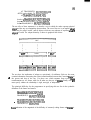
Implicit Specification of Frames
The typical manipulator has 6 degrees of freedom, which allow it to be positioned at an
arbitrary position and in an arbitrary orientation. Frames also have 6 degrees of freedom,
corresponding to 3 directions of translation and 3 angles of rotation. It follows that if a
single pointing of the manipulator is to imply a unique frame explicitly, there are no spare
degrees of freedom. The absence of spare degrees of freedom makes it quite difficult to
position the manipulator accurately.
This problem frequently arises in the context of manipulators which are programmed by
guiding them through the motions. It is not hard to guide a manipulator manually to a good
grasping position to pick a part out of a pallet. However, it can be quite difficult to guide it
manually to a good orientation such that when the manipulator attempts to remove the part
from the pallet there is no binding. The need for orientation accuracy becomes much more
crucial when it is beiFg used to define a world model, since any angular error may be
multiplied by some long moment arm in the AL program, whereas in a guiding system the
process of grasping is always spatially localized at the point where the angular error was
made.
. In order to avoid this difficulty, it is convenient to use multiple pointings to define each
frame implicitly. The first, pointing may define the origin of the frame, the second may
define one axis of the frame, and the third may define one plane of the frame. In this
manner, each pointing determines position only, and there is no need to have orientation
accuracy.
_ The Bendy Pointer
The manipulator extremity must be provided with some sort of sharp pointer so that it can
be used as a ‘precise measuring tool. The pointer must have a shape suitable for reaching
into awkward places such as the inside of a screw hole, the interior of a box, and so forth. In
order to make the shape of the pointer compatible with all kinds of unforseen obstructions, it
is desirable to design a pointer w’hich may be bent by the user into an arbitrary shape. Such
a special device will be referred to as a bendy pointer.
Whenever the user wishes, he e may deform the bendy pointer into any new configuration
which appears to be convenient for the next pointing operation. Having deformed the
pointer, the user must calibrate its new end position by using the pointer to point to a.
standard fiducial mark at a known location in the laboratory. From the frame of the fiducial
and the frame of the gripper, the system can infer the translation which takes the gripper
frame into the bendy pointer.
A possible refinement to the bendy pointer would be to provide it with some sort of terminal
sensor. For example, if the object being measured were metallic, one could construct an
electric circuit and measure current through the pointer. Another possibility would be to use
some sort of infra red or fluidic device. Adding a sensor would improve the sensitivity of
locating the pointer accurately, but it would also create problems of compatibility with being
able to bend the device. For this reason, it will be assumed that there is no terminal sensor,
and the user is required to eyeball the positioning.
One way of fabricating a bendy pointer would be to have a 6 inch length of wire coat
hanger protruding from a metal block which is suitably shaped for grasping by the
manipulator. Another possibility would be to use a linkage made from 2 or 3 thin rods
connected by ball joints with clamps. A bead and tendon chain might also be suitable. An
alternative to the bendy pointer would be a tool set consisting of an assortment of rigid
pointers of commonly useful shapes which could be quickly attached or detached. Whatever
type of pointer is used, it must be reasonably rigid under gravity.
Prior Art
-=.
The idea of guiding a manipulator to teach it a sequence of motions is well known and in
common use at many laboratories and in several commercial products. However, adopting a
guiding approach towards the generation of world models as proposed here has not been
previously reported.
The idea of using a bendy pointer with a manipulator has not appeared in the literature,
although this idea is related to the previous use of a rigid retractable pointer. Such a rigid
pointer with a sensing capability was initially installed on the IBM arm in 1973 as a means
for detecting touch $;h low inertia, a capability which was used, for example, to detervine., ,
orientation of parts. Subsequent to its installation, this sensing device was frequently *usA
as a pointer to a set of fiducial marks in order to verify that the manipulator’s calibration
had not drifted.
Positioning a mechanical pointer in 3-d space is in some sense analogous to the action of
moving and rotating a cursor in a 2-d graphics system. In a 3-d graphics system, the cursor
has 3 translational and 3 rotational degrees of freedom. While there is no mathematical
difficulty in moving a 3-d cursor, there is a substantial human engineering problem in
orienting the cursor or even in simply visualizing an oriented frame. One of the authors has
dealt with this problem in the context of representing 3-d objects [31 and’ found it desirable
to use implicitly defined frames rather than explicitly defined frames to specify how ob&cts
were to be attached. The actual coding of the implicit frame definition routines was done by
Roger Evans, who subsequently coded similar routines into the ML language used with the
IBM arm. The latter routines are used to specify absolute frames, but there is no notion of
subpart hierarchies with affixment relations, and no notion of relative transes.
Conversations with members of the Stanford Hand-Eye project indicate that several people
had considered many if not most of these ideas back in 1973, but at that time the need to
design and implement AL superseded the need for interactive world model generation.
HYPOTHETICAL PROTOCOLS
Initial State
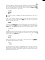
This section presents hypothetical protocols between the proposed system and a user who*
wishes to generate the world model corresponding to the tree shown earlier. The subpart
hierarchy is indicated below:
WORLD
FIDUCIAL
ARM
POINTER
BEAM
BORE
BRACKET
BORE
,
HANDLE,
B O L T
GRASP
The reasons for including the fiducial mark, the arm, and the pointer in this hierarchy will
. become clear later on when the topics of system architecture and display facilities are
discussed. At the start, when the system is first turned on, the subpart hierarchy is as shown
below:
WORLD
FIDUCIAL
ARM
POINTER
I
’
.
In the protocols which follow, system output is shown in upper case, user responses are
e
shown in lower case, and explanatory material is contained in curly brackets {like this),
When the system is ready for further user input, it prompts the user with an asterisk (I).
Protocol To Build Subpart Hierarchy
*new bracket
( This mans that a new object called bracket is to be added
to the subpart hierarchy.)
*nonrigid
( This specifies that bracket is nonrigidly af’xed to world,)
Ull
*(Here the user moves the manipulator to point to the bracket frame, The det&&s
protocols for this type of operation are given in the next section.)
of the
ed:tbracket
( This sets a context in which all future new o&xts ate
subparts of bracket until the context is changed. Here “d:”
stands for dad. When the system was first turned on, the
initial context was d.+world.)
*new bore
*rigid
( These two steps add a new object called bore to the
hierarchy as a subpart of bracket and cause bore be
a affixed rigidly to bra&et.)
’ *(Here the user moves the manipulator to point to the bore frame. The details. of the
protocols for this type of operation are given in the next section.)
*new handle
*rigid
*(Here the user moves the manipulator to point to the handle frame.)
+d:tworld
( AlI ft(lure new objects are subparts of world agafn.)
*new beam
*nonrigid
*
*{The user points to the beam frame.)
rkd:cbeam
( Future new objects are subparts of beam.)
- *new bore
( The system is capable of distZnguisAing beam-bore from
bracket-bore)
*rigid
*((The user points to the bore frame.)
*d:cworld
*new bolt
*nonrigid
.
*{The user points to the bolt frame.)
*d:tbolt
*new grasp
*rigid
*{The user points to the grasp frame.)
*
Protocol To Point To Frame
( Suppose the user bends the pointer into a new shape. He
now wishes to calibrate it.)
wsetfid
( This macro expands into “free; a.+arm; +-fiducial; inverse;
)le; pointer.*a:t”. The “free” releases the arm brakes so the
user can move the manipulator manually so that the
pointer points to the fiducial mark When he Aas done so,
he pushes the “stop arm” button to proceed. The remaining
primitive stack operations compute the correct pointer
transform and are described more fully in the next
section.)
*record
( This macro records the point. It expands into “free;
a.+ I pointer;“. The user moves the arm to make the pointer
touch the current frame origin and again pushes the “stop
arin” button. The pointer location is then read and
remembered.)
*record
( This time the user records any other point on x-axis of the
current frame.)
*record
( This time the user records an? other’ pofnt on xx-plane of
the current frame. There would be other commands to select
a different axis and plane.)
*construct
{ This computes a trans from the three recorded potntings.)
*(bracket:ca:
( This gives BRACKET the computed trans.)
Protocol To Move In A Frame
. ( The user may prefer to have the pointer moved by
computer control rather than moving it himself manually.
For example, suppose Ae is defining the
frame
of
BRACKETHOLE when As has already defined that of
BRACKET.)
*free
( He manually brings the pointer near the correct place, and
pushes the “stop arm” button to proceed.)
wcbracket
( This says that the user wants to make motions with
respect to the BRACKET frame.)
*m:cpoin ter
( This says that the frame which is to do the moving is the
pointer. This is the main reason for including POINTER
in the subpart hierarchy.)
rkdz -.Ol
( This says move the pointer by a distance of .01 units in
the minus z direction of the BRACKET frame. This macro
expands into “6.+-v 0 0 41;
dmove;
t”. Agatn the
commands will be explained later.)
*x 0
( This says move the pointer along the x axis of the
BRACKET frame until it has x=0 in that frame. Again,
x is a macro.)
Extensions
The proposed system might be extended in several possible ways.. For example, pointing by
vision could be provided to augment the manipulator pointing capability. Provision could be
made for the user to define other attributes of object models besides location and affixment.
Perhaps generic shapes such as cuboids, cylinders, or machine screws could be specified in
this fashion. If visualizing frames proved to be difficult for some users, some form of
graphics capability could be added to display frames of the objects in the subpart hierarchy,
or possibly to display even some of the generic shapes. A more speculative extension would
be a means for keeping track of a succession of world models, since such a squence could be
interpreted as an entirely new way of specifying an assembly procedure.
SOFTWARE DESIGN DETAILS
Svstem Architecture
The proposed system contains three principal “working” modules: the affixrnent e&or,
arithmetic routines, and manipulator interface roatines.
The affixment editor contains facilities for creating and modifying the subpart
hierarchy. The principal data structures asociated with this section are the tree
used to represent the hierarchy and a set of stack-structured context pointers
(called “cursors”).
r
The arithmetic section contains a full set of arithmetic operations for scalars,
vectors, and transes, together with routines for modifying the location attributes
of parts. The principal data structures associated with this section are a pair of
stacks used to hold operands. Typically, one stack is used to hold values
specifying incremental motions for the manipulator, while the other is used for
computing new location values.
The manipulator interface contains facilities for moving the manipulator under
either system or user control and for retrieving the current location of the
manipulator for use by the rest of the system. For the latter purpose, the node
ARM in the subpart hierarchy always contains the current location of the
manipulator.
In addition, there are three “service” modules: a command interpreter, display facilities, and
output facilities.
The command interpreter accepts commands typed in from the terminal aed ,: ,.,
translates them into calls on appropriate routines: Most commands’ hi&c, . ’
mnemonic text names (e.g., “getdad” to move a cursor from a subpart node to its
parent). In addition, many have single character abbreviations (e.g., “A” for
“getdad”). A macro facility for stringing together commonly occurring squences
of primitive operations is assumed to be present but will not be discussed in
detail in this document, although definitions for some assumed built-in macros
will be given.
The display routines update the screen of the user’s terminal to reflect the
current state of the affixment editor, arithmetic section, and manipulator
interface.
.
The input/output facility contains routines for saving and restoring subpart
hierarchies in files. In addition, it contains routines for translating a subpart tree
into a text file of AL declarations.
Subsequent subparts of this section will describe the display routines and the primitive user
’ commands for invoking the facilities provided by the various modules.
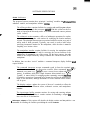
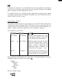
Display Facilities
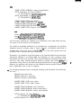
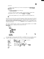
The display routines are used to provide the user with an up-to-date picture of the current
system state. To do this, the display screen is broken into an affixment editor reigon, an
arithmetic reigon, and a terminal interface reigon, as is shown in figure 1, below.
A f fixmeAt editor
M:P: WORLD atTOO
*FIDUCIAL at T 0 0 0 41.3 4.8 0
+ARM at T I.2 92.3 1.8 11.4 18.2 10.5
+POINTER at T 0 0 0 1.0 1.4 6.2
+BEAM at T 0 0 0 20.0 40.0 0
*BORE at T 0 90.0 0 0 1.5 6.0
D:
+BRACKET at T 0 0 0 10.0 60.0 0
*HANDLEatTOOOOOO
N:
*BORE at T 0 180.0 0 5.1 2.0 0
+BOLT at T 0 180.0 0 30.0 50.0 5.0
-GRASP at T 0 0 0 0 0 0
A rithmetic *section
A: STACK
1: 3.14159
2: v 1.0 0.0 1.5
3: T 90.0 10.0 18.5 0.0 1.9 2.3 1.3
B: STACK
1: v 0.1 0.0 0.0
2: <empty>
3: <empty>
Terminal interface section
renew handle
rd:tbracket
Erigid
It
Figure 1. Typical display scene
In the affixment editor section, subpart relations are indicated by paragraphing. The type of
affixment is indicated by preceeding the part name by a “*” for rigid affixment, “+” for
nonrigid affixment, and ,I-” for independent affixment. Cursor positions are indicated by
placing the cursor name on the appropriate line. Finally, the location attributes for each
node are indicated in the “at” expression. In the case of rigid or non-rigid affixment, relative
position of with respect to the parent is printed. For independent affixment, location with
respect to the WORLD node is shown.
The arithmetic section displays the current contents of the top three locations in the stacks.
Values are shown in the same format in which they would be read in from the terminal, i.e.,
t171
scalars are merely typed out, vectors have “V” followed by three scalars, and transes have
“T” followed by three rotation angles and three displacement values.
The terminal interface section is simply an area for the operating system’s page printer to go,
and shows the last few commands typed by the user. As characters are typed by the user, this
is where they are put.
.
r
For efficiency, random access graphics would be used to update only those parts of the
display that are changed from command to command. However, it should be pointed out
’ that the design shown uses only text characters for typeout. Thus, one reasonable alternative
would be simply to type out the whole screen each time. On reasonably fast terminals (300
baud or greater) this shouldn’t prove too much of a burden.
Affixment Editor
The affixment editor contains facilities for creating and modifying the subpart hierarchy,
which is stored internally as a tree of part nodes. Each such node contains the following
information:
--.
PNAME -L The print name of the node. For instance, “BORE”. Notice that
these names are, not necessarily unique.
DAD -- Pointer to the parent node. The special node WORLD acts as an
ultimate ancestor.
SON -- Pointer to the node most recently affixed to this one.
EBRO and YBRO -- Pointers to the elder and younger brother nodes, ,
respectively. For example, EBROLNI points to the node that was SON[DAD[NJ]
when N was affixed to DADLNI.
HOWAFFIXED -- An integer telling how the node is affixed to its parent.
There are three kinds of affixment: rigid (I) an&nonrigid (2) have essentially
the same meaning as given in the AL document. independent (0) is a special
kind of affixment used for nodes that have a subpart relationship with their
parents but whose locations are independently specified. Independent affixment
is primarily useful as an intermediate step in editing a structure.
XF -- A homogeneous transformation used to specify the location of the node.
This is internally stored as a 4 by 4 matrix. If the affixment is rigid or nonrigid,
XF specifies the location of the node with respect to its parent node. If the
affixment is independent, XF specifies the location with respect to WORLD.
Primitive commands are provided for creating new nodes, deleting old ones, modifying the
affixment links, copying structures, and various other useful editing functions. These
commands will be discussed in a moment. A number of context pointers, called cursors, are
used to specify some of the arguments to the editing primitives. Such cursors are stack
structured and typically are named by a single character followed by a colon. The following
cursors are included in the current design:
CURNODE (“N:“) -- gives the node on which the user is currently working.
CURDAD (“D:“) -- gives node to which subparts are to be affixed.
’
CURPATH (“Pi’) -- gives root node of current subtree for name recognition.
..
-gives
the
current
motion
reference frame. All motion
CURREF (“R:“)
commands are to be made with respect to the location frame of this node.
CURMOVE (“M:“) -- gives the current motion frame. All motion commands
actually move the location frame of this node.
CURTOP (‘IT:“) -- gives the root node of the displayed subtree.
CURKILL (“K:“) -- gives the root node of the most recently deleted subtree.
As mentioned before, cursors are stack-stuctured. This means that typically whenever a new
value is assigned to a cursor, the old value is saved away (to a depth of four) where it can
be recalled if need be. This facility provides a nice way for a user to recover from errors, as
well as t,o suspend temporarily one editing sequence and go do something else.
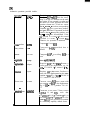
The following operations are supplied for modifying the contents of cursors:
I
0 beration
Typein,
1 Descrifition
Set cursor
c:c<node spec>
~Pushes down the old value of cursor c:,
then sets the new value <node spec>,
, which may be a node name or a cursor
name. For instance, “n:tbeam” followed by
“d:tn:” would set the current value of both
N: and D: to BEAM.
Pop cursor
c:T
Restores the previous value of c:. May be
combined with assignment, as in “d:cn:t*,
which pops N: into D:.
Get father
CA
Replaces c: with DAD[c:l. Does not save
previous value.
Get son
c:v
Replaces c: with SON[c:l Does not save
previous value.
Get brothers
cx and c:>
Replace c: with YBRO[c:l and EBRO[c:],
respectively. Do not save previous value.
Here c: has been used to stand for any cursor name. An additional property of the cursor
commands is that they remember the last cursor operated on. If a cursor designation is left
off of a command, then the last cursor specified will be used. For instance, “n:A& will move
the cursor N: so that it points at its great uncle. One fine point here is that value fetching is
done before assignment. Thus, for a sequence like
n:cbracket
n:tbeam
d:tn:t
A
D: will wind up pointing to WORLD (The DAD of BEAM) and N: will point at
BRACKET.
Earlier, it was stated that node names need not be unique. This can cause difficulties in
cases where a user wishes to address a node by its name. For instance, in our example
structure, a user might want to type,
n:tbore
Here, there are two_possibilities: one a subpart of BEAM and one a subpart of BRACKET,
and the system will not know which is meant. Such ambiguities may be resolved by naming
an ancestor node whose subtree contains only one node with the name in question. Thus, the
sequence
n:tbracket.bore
<
would place the cursor N: as shown in figure 1. In many cases, one wishes to work for an
extended period in one subtree. To facilitate this, the cursor P: may be used to supply a
default ancestor node. Thus, the sequence
. ;.,
p:tbracket
n:cbore
<
would also place the cursor N: as shown in figure 1. Note, however, that it is still pixsible to
have inherently ambiguous namings. For instance:
BEAM
HOLE
HOLE
This situation arises quite naturally as an intermediate state in cases where a previously
defined structure is being copied and modified Therefore, it is not outlawed. If a user
wished to point at such nodes, he must get to a nearby node and then use cursor moving
operations to get the rest of the way.
WI
The following primitives are used to edit the tree structure:
Operation
Typetn
Make new nocle new <name>
D escri #ion
Creates a new node with the specified
name and affixes it as an independent
subnode -of WORLD. Sets N: to point at
the new node. (Old value of N: is pushed).
Affixment
caffixment type> Affixes the node pointed to by N: to that
pointed to by D: in the indicated manner.
Leaves N: and D: as they were. Updates
links and location attributes appropriately.
(Discussed further below).
Kill structure
kill <node spec>
Deletes the subtree rooted at the named
node. Sets K: to point at deleted structure.
(Previous value of K: is pushed). If <node
spec> is omitted, then N: will be assumed.
Un kill
‘k:t
Popping a node off the K: stack restores
the subtree rooted there to life. The
restored structure will be linked back onto
its parent in the same way as during its
previous existence.
Copy structure
copy <node spec> Copies the subtree rooted at <node spec>
and sets N: to point at the copy. (The
previous value of N: is pushed.) If <node
spec> is omitted, then N: will be assumed.
Merge structure merge
Unlinks all subparts from the node
pointed to by N: and makes the
corresponding affixments to the node
pointed to by D:. Leaves N: and D: alone.
The affixment operation comes in three flavors: rigid, nonrigid, and independent. In the
first two cases, the XF attribute of the node must be set to the current relative position of the
node with respect to its new parent, while in the last case, the XF must be set to the current
absolute location of the node, i.e., its location relative to WORLD. This is done as follows:
1. Check to be sure that the affixment requested will not cause a circular
structure by verifying that N: is equal to D: and is not an ancestor of D:. If a
circular link is being proposed, print an error message and quit. Otherwise, go
on to step 2.
2. Compute the current absolute location of the node pointed to by N: and store
the result away in XF[N:]. A ‘method for computing absolute locations will be
WI
given later.
3. Unlink the node pointed to by N: from its current parent. Set YBRO[N:] and
EBRO[N:I to null.
4. Set HOWLINKED[N:I to the new link type.
5. If the new link type is rigid or nonrigid, compute the absolute location of the
node pointed to by D:, call it T, and replace XF[N:I by T%XF[N:].
6. Link the node pointed to by N: as the youngest son of the node pointed to by
.D:.
Note that one side effect of the way the kill command is defined is that storage for a deleted
structure will not be reclaimed until the structure falls out the bottom of the K: stack (i.e.,
after four deletions). If this should ever get to be a problem, then a “purge the kill stack”
operation is easy to add. (In fact, repeating “k:+k:” three times will flush all but the most
recently killed object).
The “merge” command provides a useful way to perform editing operations on sets of nodes.
For,instance, suppose we have an affixment structure like this:
WORLD
+BOX
*HOLE 1
+APPROACH
*HOLE2
+GRASP
+BOTTOM
...
COVER
+GASKET
e
.I
!
’
and suppose that we wish to make holes HOLE 1 and HOLE2 in the corresponding position
in parts COVER and GASKET. This can be done by the following editing sequence:
new tmp
d:cn:
p:tbox
copy hole1
rigid
n:t
copy hole2
rigid
n:t
(Use TMP as a “bin” for holding the set of of holes.)
@ffixing to TM PI
(Don’t keep having to type “BOX “)
{Affix a copy of HOLE I rigidiy to TMP)
(Gets HOLE I off of N: stack, which reverts to TMP.)
(Repeat sequence for HOLE 2 )
.
At this point the affixment structure looks like this:
WORLD
-TMP
*HOLE 1
+APPROACH
*HOLE2
+BOX
*HOLE 1
+APPROACH
*HOLE2
+GRASP
+BOTTOM
. . .
+COVER
+GASKET
with N: and D: both pointing at TMP. Now we will merge a copy of TMP into COVER
and TMP itself into CASKET.
copy
d:+cover
merge
kill
n:t
d:cgasket
merge
kill
-i’ (IV: points at a copy now)
(Will merge into COVER )
{Perform merge operation]
(Kill off copy of TMP, which at this point has no subnodes left]
(Get pointer back at TMP)
(Will merge TMP onto GASKET)
(Kill off TMP, which is now childless.)
The final affixment structure is:
WORLD
+BOX
*HOLE 1
*APPROACH
*HOLE2
+GRASP
+BOTTOM
. * .
+COVER
*HOLE 1
+APPROACH
*HOLE2
+CASKET
*HOLE 1
+APPROACH
*HOLE2
Arithmetic Section
The arithmetic section provides the user with a means for performing computations on
scalars, vectors, and transes. All operations are performed in Polish on one of two operand
stacks, and the results are stored back in the stack on which the operation was performed. In
addition, facilities are provided for the user to enter values from the terminal and to retrieve
and modify the location attributes of nodes in-the affixment structure. Since the current
value of ARM and POINTER always give the positions of the manipulator and the pointer,
respectively, this means that the user can use the results of pointing operations to define
relative or absolute part locations.
The arithmetic section contains two functionally identical 100 element operand stacks, called
“A:” and “B:“. A third and somewhat shorter stack, called “0:” (for ‘hops”), is provided to
facilitate error recovery. Any time a value is popped off one of the operand stacks, it is
pushed onto 0:. Thus, if a careless user makes a mistake and invokes the wrong operator, he
can get his operands back by popping them off 0:. A S with all stacks in the system,
overpushing causes the oldest element to fall out the bottom.
The following elementary stack operations are provided for manipulating values. Here, S:
stands for any arithmetic stack.
Operation
Typein
Description
Fetch value
s:t<value>
Pushes <value> onto the stack. <value>
may be a literal (described below), a
register name (as in “a:tb:” or a+o:?j, or
an absolute or relative node location.
Relative locn.
s:te<node spec>
Push the XF attribute of the specified
node to the stack.
.., ’
Absolute locn.
s:tl<node spec>
Pushes the lo&ion of the specified node
with respect to WORLD.
POP
s:t
Pops the previous contents of S: into S:.
Edit
edit <lhs>
Places the string “<lhs>t<value>” into
system line editor. (see below)
Exchange
SW
Exchange top two elements of S:
Store relative
e<node>t<value> Copy the specified value into the XF
attribute of the specified node.
Store absolute
I<node>t<value>
Modify the affixment structure SO that the
absolute location of the specified node will
have the specified value.
1241
The format, used for typein of literal values is the same as that used by the display routines’
to type them out. For instance,
a:t3.14159
(pushes the scalar value, 3.14159, onto A:)
a:tv x y z
(pushes vector (x&, where xJJ are scalars onto A:)
a:tt o 8 4 x y z (pushes a trans corresponding to a rotation of o degrees
about the z-axis, then 8 degrees about the y-axis, then 6
degrees about the r-axis again, followed by a translation by
vector (x,y,z). A gain, o, 8,& x, y, and z are a&l scalars.)
r
The “edit” command is intended to facilitate modification of values that may be a little off,
due to inaccuracies in pointing. Essentially, the line editor is a facility maintained by the
time sharing system that allows a user to erform local editing operations on text that has
been typed ahead ‘but not yet activated. Plo1 (S ome “smart” terminals offer similar local
editing of text input). One principal advantage of such a facility is that it provides users
with an efficient, flexible, and uniform set of editing conventions. For instance, suppose that
the current location of HANDLE (with respect to BRACKET) is “T 0 179.3 1.8 0 0 0.01”.
We “know” that this just cannot be quite right, since rotation angles are assumed (for the
moment) to come out to even fives of degrees. Also, we strongly suspect that the fini
displacement value ought to be “0”. The value can be patched up by the following command
sequence:
edit @handle
(T&s loads the line editor with the text:
“sAandie.u-t 0 179.3 1.8 0 0 0.01”
and puts the user in local editing mode.)
shandlett 0 180 0 0 0 0
(The user has edited the line to the form shown here and
actitiated by typing carriage return.)
In cases where the thing being edited is a stack register, the stack value is popped into the
line editor (without affecting the “0:” stack). For instance, our example could also have been
performed by:
a:tehandle
edit a:
a:tt 0 1800000
ehandletazt
t251
Except for nodes whose immediate parent is WORLD or which are independently affix&
absolute locations are not directly available in the affixment editor’s data structure. However,
the required computation is very straightforward. The system uses the following algorithm,
expressed here in an informal procedural notation.
(Assume N is a node whose absolute posi‘iion is to be computed.) *
XtXF[NI; (X will eventually be the absolute locatfon.)
WHILE HOWLINKEDEN]+“independent” DO
BEGIN
NtDAD[NI;
XtXF[.N]*X;
END;
(Here, X - absolute location of N, i.e., location with respect to WORLD. )
A somewhat similar problem arises when storing away the absolute location of a node, since
non-independent nodes keep the relative location with respect to their parent node. Here, the
effect desired in asserting that a node N has a new absolute location X is implicitly to
update the absolute location of all non-independent descendents of N. Also, if N is rigidly
affixed to its parertt, then the absolute location of the latter must also be updated. The
following algorithm for updating absolute locations will do all this:
u ssume N is a node whose absolute location is to be set to X, I.e., we have
just executed a statement like “Ihr + Xn.J
WHILE HOWLINKED[NJ=“rigid” DO
BEGIN
XtX*XF[Nl-I;
NtDAD[NE
END;
, (Here, N fs a nonrigidly affixed node wAose absolute location must be set io
Xl
IF HOW.LINKED[Nl-“nonrigid” THEN
XF[N]c(absol@e lot of DAD[NI)%X
ELSE
XF[N]cX;
,
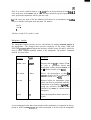
Arithmetic operations provided include:
3peratton
Binary ops
Typein
s:+ - 1 I
Description
Computes S:[ll <op> S:[Ol Does the “usual”
thing if the top two elements on the stack
are scalars. If one operand is a scalar and
the other is a vector, performs the scalar
operation element-wise. If both are vectors,
then “+” and “-” work on corresponding
elements, “*” gives vector inner product,
and “I” is undefined. If operands are both
transes, then “a” returns the product, and
“+” ” - ”, and “I” are all undefined. If the
to; operand is a vector and the second
operand is a tram, “*” returns Tw.
Otherwise, the operation is undefined.
3ross product
s:cross
Computes S[ 11 cross SlOl
Jnary minus
-- s: -)
C o m p u t e s 0-S:IOl, provided that is
defined.
nverse
s:in verse
Computes S:103’ ‘, providing S:[Ol is a
trans
tiagnitude
s:magn
Gives sqrt(S:[Ob&~Ol)
Xsplacemen t
s:dpart
Requires S:[Ol to be a trans. Returns a
vector equal to the displacement. e.g., for
S:[O] - T 0 180 30 1 3 5, returns V 1 3 5,
cotation
s:rpart
Requires S:[Ol to be a trans. Produces a
trans with zero displacement but the same
rotation as S:[Ol. E.g., if S:[Ol - T 0 180 30
1 3 5, returns T 0 180 30 0 0 0.
Vector trans
s:vtrans
Converts vector S:[Ol into a trans with
zero rotation and S:[Ol as the displacement.
E.g., if S:[Ol - V 1 3 5, produces T 0 0 0 1
3 5.
s:construct
Constructs a new trans T from vectors
S:[Ol, S:t 11, and S:Rl, such that
T-*rlrS:[Zl-(V 0 0 0), T-l*S:W(V 0 0 z)
for some z>O, and T%:[Ol-(V x 0 z) for
some x,z (x>O). This operation is essential
for constructing implicitly defined frames.
6
Zonstruct trans
Here, S: is used to ‘stand for either A: or B:, S:EOl refers to the top element of stack S:, S:[ 13
refers to the next element down, and so forth. All these operations pop their operands off the
stack, perform thecomputation, and the push the result.
AS’ with cursors, the name of the last arithmetic stack referred to is remembered, and wjll be
used as a default in subsequent stack operations. For instance:
azt2.54
t 10.0 *
r(r
will leave a result of 25.4 on the A: stack.
Manipulator Interface
The manipulator interface provides the user with facilities for making controlled motions of
the manipulator. The principal data structures employed are the nodes ARM and
POINTER provideh.in the affixment data structure, and the cursors M: and R:, which are
used to request computer-controlled motions of the manipulator. The primitive commands
involved are given below:
Operation
Typein
Description
Absolute move
s: amove
Requires that the S:[Ol be a frame. (If not,
an error is generated). Moves the
manipulator so that (absolute location. of
M:) = (absolute location of k:) r(r S:[O].
Diff. motion
s: dmove
Moves’ the manipulator so that the
absolute location of M: is changed by
(absolute location of R:) * S:[O].
Free arm
free
Releases brakes on manipulator joints,
which can then be positioned manually.
Completion of positioning is signalled by
typing any activation character at the
terminal or by means of a button on the
manipulator
Joystick
Places the manipulator under control of a
joystick.
As was mentioned earlier, the current location of the manipulator is assumed to be always
present in ARM. In actual practice,‘it is rather inconvenient to do this while the manipulator
tw
is being moved. Therefore, it is assumed that the value is only updated at times when the
system is at a convenient place, such as at the top of its command interpretation loop. Such a
policy is unlikely to cause any difficulties for the user.
It is unlikely that the “joy” command would be implemented at Stanford, where manual
positioning is used instead. The command is included to give some indication of where a
..
joystick would fit into such a system.
Input/Output Facility .
This module contains routines for saving subpart trees onto a file and for reading saved
structures back into the affixment editor. This allows the user to spread his work over
several terminal sessions without having to recreate the entire structure each time. In
addition, a routine to translate a subpart tree into AL declarations is provided.
The commands are given below:
--,
O#erution
Tgfiein
D escrif, tion
save. structure
save <filename>
Saves the structure pointed to by N: on the
file specified by <filename>. Has no effect
on the affixment editor data structures.
load <filename>
Reads the structure stored on the named
file into the affixment editor’s memory.
Causes N: to point at the newly read
structure, which is affixed as a n
independent subpart of WORLD. The
previous value of N: is pushed’.
’
al <filename>
Translates the structure pointed to by N:
into the appropriate set of AL declarations
and writes the text on the specified file.
restore
a
AL code
When writing the AL declarations, the system will
unambiguous names. For instance, if the structure is
WORLD
BRACKET
BORE
HANDLE
BEAM
BORE
then the command sequence
n:tworld
al decls.al
.
use
the subpart hierarchy to produce
t291
would
produce
declarations
involving
“BRACKETHANDLE”, etc. For instance:
“BRACKET”,
“BRACKETJ5ORE”,
FRAME BRACKET, BRACKETwBORE,BRACKETHANDLE;
..
ASSERT FORM (SUBPART,BRACKET,BRACKETJOREh
ASSERT FORM (SUBPART,BRACKET,BRACKETHANDLEh
AFFIX BRACKET-BORE TO BRACKET RIGIDLY
AT TRANS(ROT(X,MO),VECTOR(!j. 1,2,0));
AFFIX BRACKETHANDLE TO BRACKET RIGIDLY
AT TRANS(ROT(X, 180),VECTOR(O,O,O)h
IMPLEMENTATION STRATEGY
The proposed pointing system could be implemented in a minidomputer with at most 16k
words of memory. However, at the Stanford University Artificial Intelligence Laboratory it
would be substantially easier to implement, modify, and use the pointing system if it were
implemented on the large time sharing machine. The only portion of the design which
inherently assumes that this machine would be used is the line-edit feature in the arithmetic
section.
A preliminary version of the system has been implemented in SAIL/’ I1 using record
structures for the subpart hierarchy, and using available display primitives. The preliminary
version only allows transes in the arithmetic stacks, has no user defined macros, and uses a
symbolic debugger, BAIL, 1121 for command scanning. With BAIL, instead of the command
syntax described earlier, users type SAIL procedure calls which are then interpreted.
The more pessimistic of the authors believes that the full system could be operational with
about 2 man months of effort. However, it is not clear that implementing the full system at
the present time is necessarily the most desirable use of manpower.
The authors do not wish to be accused of succumbing to the Mikado syndrome which
consists of saying that since the implementation is as good as done, for all practical purposes
it is done, and if it’s done, why not say SO? ~131 On the other hand, it should be stressed that
whether or not the full system proposed here is actually ever implemented, tests with the
preliminary version demonstrate the feasibility of generating object models in a resonably
simple manner. What otherwise might have been a serious drawback to the use of high level
languages for manipulation is, therefore, not a serious problem at all.
.
CONCLUSIONS
This paper has addressed the topic of generating object r&dels for programs in a high level
manipulator language. An interactive system was proposed in which the manipulator itself is
used as a measuring tool in three dimensions. One component in this system is a bendy
pointer whose deformation may be calibrated against a known fiducial mark. Hypothetical
protocols involving such a’ system were presented, as well as details about the design of the
underlying software.
Such a system would materially speed up the process of generating world models for AL
programs. Most of the proposed system could be adapted for other methods of pointing or
for other high level manipulation languages. The system could be expanded to permit
additional descriptive data about obbcts, or to keep track of a squence of world models as a
new means of specifying an assembly procedure.
A preliminary version of the system has been implemented and tested. This preliminary
system demonstrates that specifying object models can be a much easier process than might
otherwise have bee6 believed.
REFERENCES
[l] “AL, A Programming System For Automation,” R. Finkel, ‘R.’ Taylor, R. Bolles, R. Paul,
and J. Feldman, Stanford Artificial Intelligence Laboratory memo AIM-243 and Stanford
University Computer Science report STAN-CS-456, November 1974.
[2] “Geomed,” Bruce G. Baumgart, Stanford Artificial Intelligence Laboratory memo
AIM-232 and Stanford University Computer Science report STAN-CS-414 May 19’74.
[3J “Procedural Representation of Three Dimensional Objects,” D, D. Grossman, IBM
,
Research report RC-5314, March 14, 1975.
[4] “Designing With Volumes,” I. C. Braid, Cantab Press, Cambridge, England, 1974. Also
“The Synthesis of Solids Bounded by Many Faces,” I. C. Braid, Communications of the
ACM, Volume 18, Number 4, p. 209, April 1975.
[53 “An Introduction to PADL,” Production Automation Technical Memorandum 22,
University of Rochester,-December 1974.
[S] “Real-time Measurement of Multiple Three-Dimensional Positions,” Robert P. Burton,
University of Utah report UTEC-CSc-72-122, June 1973.
[ 7 3 “Visual Robot Instruction,” D. A. Seres, R. Kelley, and J. R. Birk, Proceedings of the 5th
International Symposium on Industrial Robots, held at IIT Research Institute, ,Chicago,
Illinois, September 1975.
[8] “Artificial Intelligence - Research And Applications,” edited by Nils J. Nilsson, Stanford
Research Institute Project ~3805 Progress Report, p. 16, May 1975.
[9] ‘*Orienting Mechanical Parts With a Computer u Controlled Manipulator,” D. D.
Grossman and M. W. Blasgen, IEEE Transactions on Systems, Man and Cybernetics,
September 1975. .
[ 101 “Monitor Command Manual,” Brian Harvey, Stanford Artificial Intelligence Laboratory
Operating Note 54.3, December 1973.
[ 1 l] %AIL User Manual”, Kurt A. VanLehn, ed., Stanford Artificial Intelligence Laboratory
memo AIM-204 and Stanford University Computer Science report STAN-CS-73-373, July
1973, revised October 1975.
[ 121 “BAIL - A Debugger for SAIL,” John F. Reiser, Stanford Artificial Intelligence
Laboratory memo AIM-270 and Stanford University Computer Science report
STAN-CS-75-523, October 1975.
I1 31 “The Mikado,” W. S. Gilbert and A. Sullivan
, .