1
STANFORD ARTIFICIAL INTELLIGENCE LABORATORY ----. MEMO AIM- 243
j
STAN-CS- 74 0 456
AL, A PROGRAMMING SYSTEM FOR AUTOMATION
BY
RAPHAEL FINKEL, RUSSEL TAYLOR, ROBERT BOLLES,
RICHARD PAUL AND JEROME FELDMAN
SUPPORTED BY
NATIONAL SCIENCE FOUNDATION
AND
ADVANCED RESEARCH PROJECTS AGENCY
ARPA ORDER NO. 2494
COMPUTER SCIENCE DEPARTMENT
School of Humanities and Sciences
STANFORD UNIVERSITY
STANFORD ARTIFICIAL INTELLIGENCE LABORATORY
MEMO AIM-243
NOVEMBER 1974
COMPUTER SCIENCE DEPARTMENT
REPORT CS-456
AL, A Programming System for Automation
Raphael Finkel, Russell Taylor, Robert Bolles, Richard Paul, Jerome FeldmanC4
AL is an high-level programming system for specification of manipulatory
tasks such as assembly of an object from parts. AL includes an ALGOL-like
source language, a translator for converting programs into runnable code, and
a runtime system for controlling manipulators and other devices. The system
includes advanced features for describing individual motions of manipulators,
for using sensory information, and for describing assembly algorithms in terms
of common domain-specific primitives. This document describes the design of
AL, which is currently being implemented as a successor to the Stanford
WAVE system.
:<
Jerome Feldman is now at the University of Rochester.
This research zvas supported in part by the National Science Foundation under contract No.
C+42906 and in part by the Advanced Research Projects Agency of the Office of Defense
under Contract No. DAHC-15-734-0435.
The views and conclusions in this document are those of the authors and should not be
interpreted as necessarily representing the official policies, either expressed or implied, of the
funding agencies.
R eproduced i n the USA. A vaiiable f r o m
S pingfield, Virginia 2215 1.
the National Technical Information Service,
Page ii
FOREWORD
This document describes the new hand language, AL. It is not intended to be a final language
specification or a user’s manual. Rather, it is a working document presenting a number of related
ideas concerning a system for programmable automation. These ideas cover a broad range of
topics: arm servoing, parallel processing, assembly world modelling, strategists, and language
design. We have tried to combine these into a coherent system. However, as you read this
document you will notice that some topics have been explored more than others, some
explanations contain more detail than others, and some questions are left unanswered. Various
portions of the system have already been implemented.
Interested persons unfamiliar with the background for this work will find it useful to read The
Use of Sensory Feedback in a Programmable Assembly System [Belles and Paul].
We would like to thank those people who have made numerous suggestions and have helped
implement various parts of the system. In particular,-we would to thank Bertrand Meyer, who
implemented the scanner and parser, Botond Eross, who is implementing the PDPll runtime
monitor, Bruce Baumgart, who assisted with the illustrations, and Larry Tesler, whose document
preparation program PUB was used to prepare this paper. We also wish to thank D. Whitney, J.
Nevins, and D. Killoran of Draper Labs and W. Park of Stanford Research Institute for their
helpful criticisms and suggestions.
During the period in which the work reported here was performed, Russ Taylor was supported in
part by a grant from the Alcoa Foundation, Raphael Finkel was supported by a NSF fellowship,
and Robert Bolles was supported in part by the Hertz Foundation. We would like to thank all
these agencies for their kind assistance.
The English language has no genderless personal pronoun; without any implication of sexism we
use arbitrary forms in its place.
TABLE OF CONTENTS
CHAPTER
Page iii
PAGE
1 AN OVERVIEW OF AL
1.1 INTRODUCTION
1.2 PHILOSOPHY AND DESIGN GOALS
1.21 DATA AND CONTROL STRUCTURES
1.2.2 MOTION SPECIFICATIONS
1.2.3 USE OF A PLANNING MODEL
1.2.4 USE OF DOMAIN-SPECIFIC KNOWLEDGE
1.2.5 THE RUNTIME SYSTEM
1.2.6 PROGRAMMING AIDS
1.3 GENERAL SYSTEM OUTLINE
1.3.1 HARDWARE
1.3.2 SOFTWARE
1.4 THE AL COMPILER
1.4.1 PARSER ’
1.4.2 EXPANDER
1.4.3 TRAJECTORY CALCULATOR
1.5 USER FEATURES
1.5.1 PROGRAM FORMULATION
1.5.2 PROGRAM COMPILATION
1.5.3 PROGRAM EXECUTION
1
1
2
2
3
3
4
5
6
7
7
7
11
11
11
11
12
12
13
13
2 THE BASIC SOURCE LANGUAGE
2.1 DATA STRUCTURES
2.1.1 DATA TYPES
2.1.2 ALGEBRAIC DATA TYPES: SCALARS
2.1.3 VECTORS
2.1.4 ROTATIONS
2.1.5 FRAMES
2.1.6 PLANES
2.1.7 TRANSFORMS
2.1.8 PLANNING VALUES
2.1.9 ARITHMETIC
2.1.10 SOME EXAMPLES-OF ARITHMETIC EXPRESSIONS
2.2 MOTIONS
2.2.1 COMPILE-TIME AND RUNTIME CONSIDERATIONS
2.2.2 SIMPLE MOVES
2.23 CONDITION MONITORS
2.2.4 FORCE DURING A MOTION
_ 2.2.5 DEPROACHES
2.2.6 OTHER MOTION CLAUSES
2.2.7 COMPLEX MOVES
2.2.8 SEARCHES
2.2.9 CENTER
15
15
15
15
17
19
19
20
21
22
22
24
25
25
26
26
29
30
32
33
34
35
Page iv
TABLE OF CONTENTS
CHAPTER
2.2.10 CONSTANT VELOCITY MOTION
2.2.11 STOPPING
.
2.2.12 DEVICE CONTROL
2.3 AFFIXM ENT
2.3.1 THE AFFIX STATEMENT
2.3.2 THE UNFIX STATEMENT
2.3.3 MOTIONS AND AFFIXMENT
2.4 GRAPH STRUCTURES
2.4.1 EXPLICIT MODIFICATIONS TO THE GRAPH STRUCTURE
2.4.2 GRAPH STRUCTURES AND AFFIXMENT
2.5 CONTROL STRUCTURES
2.5. I TRADITIONAL STRUCTURES
2.5.2 COBEGIN-COEND
2.5.3 PARTIAL ORDERING OF SUBTASKS
2.5.4 EVENTS: SIGNAL AND WAIT
2.5.5 STATEMENT CONDITION MONITORS
2.5.6 COMMENTS
2.5.7 LABELS
2.5.8 ABORT
2.5.9 OUTPUT
2.5.10 PROCEDURES
3 COMPILE-TIME CONSTRUCTS
3.1 INTRODUCTION
3.2 PLANNING VALUES
3.3 PLANNING VARIABLES
3.3.1 ALGEBRAIC PLANNING VARIABLES
3.3.2 ATOMS
3.3.3 EXPRESSIONS, CLAUSES, STATEMENTS, AND FORMS
3.4 ASSERTIONS
3.4.1 THE ASSERT STATEMENT
3.4.2 THE DENY STATEMENT
3.4.3 CONSTRAINT ASSERTlONS
3.4.4 STANDARD USES FOR .ASSERTIONS
3.5 CONDITIONAL EXPANSION
3.5.1 PLAN IF
3.5.2 TESTING FOR ASSERTIONS
3.5.3 THE ANYTHING CONSTRUCT
3.5.4 BINDING BOOLEANS
3,5.5 PICK
3.5.6 PLAN FOREACH
3.6 THE COMPILE-TIME CHECK STATEMENT
3.7 LIBRARY ROUTINES
3.7.1 SAVING LIBRARY ROUTINES
PAGE
36
36
36
37
37
39
39
.40
40
42
43
43
45
45
46
47
48
48
48
49
49
52
52
52
55
55
56
57
58
59
60
60
61
61
61
62
64
64
65
66
68
68
71
TABLE OF CONTENTS
CHAPTER
37.2 SAVING AND RESTORING PLANNING VALUES
Page v
PAGE
71
4 VERY HIGH LEVEL LANGUAGE CAPABILITIES
4.1 INTRODUCTION
4.2 MACRO OPERATIONS AS A ‘HIGH LEVEL LANGUAGE’
4.3 MORE POWERFUL PRIMJTIVES -- AN OVERVIEW
4.4 CALLING HIGH LEVEL PRIMITIVES
4.5 WORLD MODELLING OVERVIEW
4.6 INFORMATION ABOUT VARIABLES
4.7 OBJECT DESCRIPTION
4.7.1 ONE-PIECE OBJECTS
’ 4.7.2 ASSEMBLIES
4.8 EXAMPLE: WATERPUMP ASSEMBLY-PROGRAM
73
73
74
74
75
77
78
80
81
86
86
5 RUNTIME OVERVIEW
5.1 CONTROL STRUCTURES
5.2 DATA STRUCTURES
52.1 VALUE CELLS
5.2.2 GRAPH STRUCTURES
92
92
93
93
94
6 EXTENSIONS TO AL
6.1 INCORPORATING VISUAL FEEDBACK
6.1.1 NECESSARY CAPABILITIES
6.12 STAGES IN INCORPORATING VISUAL FEEDBACK
6.2 DYNAMIC FRAMES
6.3 EXTENSIONS TO OTHER ARMS AND DEVICES
6.4 FINE CONTROL
6.5 COLLISION AVOIDING
95
95
95
96
97
99
99
99
7 BIBLIOGRAPHY
100
APPENDICES
I EXAMPLE DIALOG WITH THE AL SYSTEM
103
II PROGRAMMING EXAMPLES
II.1 BOLTING A BRACKET ONTO A BEAM
11.1.1 EXAMPLE ONE
11.1.2 EXAMPLE TWO
II. 1.3 EXAMPLE THREE
II.2 EXAMPLES OF COORDINATED ACTION
II.3 A ‘VERY HIGH LEVEL’ EXAMPLE
106
106
109
111
113
120
123
III RUNTIME SYSTEM
125
TABLE OF CONTENTS
APPENDIX
111.1 THE RUNTIME SCHEDULER
III.2 TRAJECTORIES
III.3 JOINT SERVOING
III.4 INTERPRETABLE CODE
III.5 ALGORITHMS FOR USE OF GRAPH STRUCTURE
PAGE
125
126
126
128
129
-
Page 1
CHAPTER 1
AN OVERVIEW OF AL
1.1 INTRODUCTION
.
.
c
.
The development of robot manipulators such as the “Animate” has led to the belief that these
tools are in some way general-purpose devices and that they might be programmed like a
computer. As a general-purpose programmable device, the robot manipulator would provide an
answer to the need for automation of assembly in batch manufacturing industries where small
production runs rule out the use of special-purpose-equipment to increase productivity.
This document describes a new manipulator programming language, “AL” which is being
implemented as a successor to the WAVE system developed at the Stanford Artificial Intelligence
Laboratory during the last 5 years.
The aim of this work is not to provide a “hands on” factory floor programming system but rather
an experimental laboratory tool for investigating the difficulty, necessary programming time, and
feasibility of writing programs to control assembly operations.
We are designing a system for small scale batch manufacturing where setup time is the key factor.
We will rely on a symbolic database and previously defined assembly primitives to minimize the
programming time. The system will be capable of top level planning and the intelligent
interpretation of user defined primitives.
The batch manufacturing environment is fairly structured; we will make use of this fact to do as
much computation as possible before an assembly begins. Such computation can be done offline
and in connection with the data base; during this phase, time will be spent optimizing each
operation, By performing this computation prior to the assembly, the amount of computation that
the robot must perform for each assembly is reduced.
Unlike WAVE, which followed a machine:language-like programming style with skips and
jumps, AL is a highly structured language with control structures resembling those of Algal. The
facility to work in many different coordinate systems and to evaluate general expressions is added.
The new language will provide for the simultaneous control of more than one robot either
asynchronously or cooperatively. Macro-like routines may be defined to express general-purpose
assembly primitives which will be conditionally expanded at compile time. Additional data may
be added to these routines to enable a top level strategy program to use these routines to
accomplish entire assembly operations.
The language will allow a task to be specified at several different levels of detail, ranging from
very explicit and detailed manipulator control programs to programs written in terms of “highlevel” assembly operators which the system will then translate into manipulator control programs.
When used in this latter mode, the system makes extensive use of its planning model, together
with a progressive refinement strategy in order to produce a consistent and efficient output
program.
L
INTRODUCTION
1.1
The system itself is written in the high level language “SAIL” to facilitate modification and
change. We expect to modify the language on a day-to-day basis as we start to use it and gain
experience. We will implement the language as it is defined in this document, and based on
experience we will modify it to obtain a better system.
,
1.2 PHILOSOPHY AND DESIGN COALS
A full language for planning manipulatory tasks of the complexity required for assembly needs
many features, some of which do not exist in any current system. We have identified the
following interrelated goals.
I
1.2.1 DATA AND CONTROL STRUCTURES
We believe that the principal mode of input to AL should be textual, as opposed to spoken or
manual (joystick). There are levels of complexity which are much more readily transmitted from
man to machine through an interface of symbolic text. Complicated simultaneous motions of two
arms and specifications of termination and error conditions are more likely to be unambiguously
stated through the medium of text, if for no other reason than the structure imposed on the
textual language forces a consistent framework on initially less structured intuitive ideas. Nontextual forms of input can be a very useful means for defining target locations, suggesting arm
trajectories designed to avoid collisions, and other purposes of this nature. We believe, however,
that such tools are most useful when applied in conjunction with a program text which supplies
the skeletal intent of the programmer; to this end AL should facilitate use of such input devices as
joysticks and other positioning tools during the process of programming.
The supervisor level of AL should be simple enough to allow natural teaching by showing; it
should be easy to interface such new devices as joysticks and simple vocal input into AL, although
we do not intend to do so at present.
We want to write entire programs in a natural manner. The machine-language aspect of current
manipulation languages makes it cumbersome to write long programs in any structured way. We
want a language which lends itself to a more systematic and perspicuous programming style.
Algol-like control structures are an improvement over assembly-like straight code with jumps.
Experience with languages like SAIL and WAVE has shown that text macros are a useful
feature; they reduce the amount of repetitive typing. AL should have a general-purpose text
macro system interfaced into the scanner and parser.
The datatypes available should include those types necessary to refer to one-dimensional measures
(like distance, time, mass) and three-dimensional measures (like directed distance, locations,
orientations). Arithmetic operators should be available not only for the standard scalar operations
like multiplication and addition, but also for such operations as rotation and translation.
1.2.1
PHILOSOPHY AND DESIGN GOALS
Page 3
Simultaneous execution of several processes should be available. A general mechanism for
simultaneity is desired, so that calculation and arm motion can take place simultaneously, and
several manipulators can be in independent motion.
1.2.2 MOTION SPECIFICATiONS
Experience with WAVE has shown that calculating trajectories for manipulators is a desirable
feature, although a time-consuming one. Trajectory calculations, together with all other
calculations which need only be performed once, should be done at compile time. This allocation
of effort can drastically reduce the computing load at execution time and eliminate wasteful
recomputation every time a sequence of actions is executed. This leads to a clear distinction
between compile-time and runtime.
The user should be able to demand that a trajectory pass through given intermediate points. The
primary use of this is to avoid collisions during the motion. It is also useful in specifying
complicated motions.
A wide range of exceptional conditions can occur during the motion of a manipulator: excessive
force might be exerted, a stopping condition may be met, the arm might come too close to a
dangerous region, the user may interrupt the motion manually, or some specified time limit might
be exceeded. Appropriate action must be taken as soon as any of these occurs, for example: to
start up a new concurrent process, to terminate something already active, to notify the user, to file
away a statistic somewhere in a table. Therefore, AL must allow the user flexibility in specifying
what conditions to monitor during the course of motions (and during execution of blocks of code
in general), and what to do in the case that a tested condition occurs. It is also useful to change
the nature of the test during a motion, if different segments of the motion require different types
of monitoring. This concept can be generalized to include the modification of a motion during its
execution to accomodate to changing conditions.
We make the assumption that threshold tests suffice for assembly with sensory feedback. In many
cases, threshold tests do suffice: To tell if the arm has hit something, a threshold test on directed
force works. To tell if a screw is binding, a similar test serves. In general, however, such tests lack
the ability to modify trajectories on the basis of signal strength. This lack is only partially filled
by an ability to disable and enable condition monitors during the course of a motion. It is our
hope ev&itually to include the capacity for including devices such as wrist force sensors and
vision in the servo control loop in a programmable fashion. When these fascinating prospects are
better understood, they will be included in the language.
1.2.3 USE OF A PLANNING MODEL
-
Since locations are not known exactly during the planning of a trajectory, there should be a clear
distinction between planned values and runtime values. Planned values will be used for
trajectory calculation; at runtime, trajectories will be modified if necessary to account for any
discrepancies. The planned values are therefore a database on which trajectory calculations are
computed. This database will occasionally be referred to as a zubrln model.
Page 4
PHILOSOPHY AND DESIGN GOALS
1.2.3
Assembly tasks require that one object be affixed to another. We wish to model this by having a
semantic attachment between objects. If two objects are affixed, and one moves, the second one
should move accordingly, that is, its planning value should be properly modified. Thus, the world
model must also include information on attachments of objects, since they will have an effect on
planning values. The affixment concept carries over to the runtime system, which does the
equivalent modifications of the actual values. This saves the user untold bookkeeping operations
to determine where an object is after its base has been moved.
More generally, the compiler should be able to maintain a wide variety of information about
expected runtime states. This includes not only object affixments and variable planning values,
as previously mentioned, but also information like the accuracy within which the planning value
is known, how heavy an object is, how many faces it has on which it can rest, how wide the
fingers of an arm should open to grasp it. This information may come from several sources,
including explicit assertions by the user, the output-of computer-aided design programs, and
built-in knowledge about the system hardware. Therefore, AL should have a general framework
for representing such knowledge.
In addition to its own internal uses, AL should provide a number of explicit mechanisms for
applying this information, including simple retrieval of data from the compile-time model and
conditional compilation facilities for producing substantially different object programs, depending
on planning information. Such facilities allow the user to write a single piece of code in some
generality, while avoiding the inefficiencies of many needless runtime checks and the planning of
useless trajectories for cases that will never be executed.
1.2.4 USE OF DOMAIN-SPECIFIC KNOWLEDGE
The system should have enough domain-specific knowledge to allow programs to be written in
terms of common assembly operations, rather than exclusively in terms of detailed single motions.
At the simplest level, this involves provision of a library of common assembly “macro-operations”
that can be conditionally expanded to perform particular subtasks. Beyond this, we wauld like an
interactive system that can take a “high level” description of an assembly algorithm and fill in
many of the detailed decisions required to produce a consistent and efficient output program.
The range of decisions required to convert from-a high level description to an efficient output
program is quite broad, and many of the processes involved cannot be modelled readily in terms
of the purely local mechanisms used in expanding library routines. For instance, a command like
“put the engine block on the table in an upright position” might require the system to examine
future operations on the engine block to select the best orientation to use. Similarly, many
operations produce side effects that make other tasks either easier or harder. For instance,
inserting a pin into a hole yields information about the exact location of the hole and therefore of
the object into which the hole has been drilled. If there are a number of pins to be inserted, then
it may be a good idea to insert pins into the easier-to-locate holes first and then to use the
information so gained to help with the remaining insertions. (On the other hand, such an
ordering may very well make the actual insertions more difficult because of obstructions to the
hand). The system should be familiar with such considerations and use them as it generates the
output program.
1.2.4
PHILOSOPHY AND DESIGN GOALS
Page 5
A user should be able to specify different parts of a task at various levels of detail. The system
must be able to accept explicit advice telling exactly how some particular subtask is to be
accomplished and then complete the program in a way that does not conflict with those things
that have been explicitly specified. This is especially important for early versions of AL, which
are not likely to be very “smart” and will therefore require a fair amount of explicit help.
The user should be able to describe the “intent” of a particular piece of code, at least to the extent
of specifying any (non-obvious) prerequisites or updates to the world model. This facility is
especially important for programs that mix both high and low-level primitives. Similarly, the
system should be able to show the user how it is filling in the details to produce an output
program, and why. This is very important both for debugging and for explaining to the user any
requests for advice that it must make.
1.2.5 THE RUNTIME SYSTEM
The calculation of trajectories is time-consuming but not time-critical; servoing of devices is timecritical but not especially time-consuming. For efficient code generation, modification,
documentation, and execution, we will write the compiler in a high-level language and develop
and run it under time-sharing. The runtime programs will be written in either machine language
or one of the new systems implementation languages (for example, BLISS), since time-efficient
code must be generated. As one execution computer will be required for each work station in a
factory, and as the runtime code and its memory requirements will be quite small, we will write
the runtime system for a minicomputer. The compiler could also be written for the small
computer, but this would compound the problems of writing the compiler; the computational
requirements are much higher during compilation than execution, so implementing the compiler
on the mini would necessitate either an overly large minicomputer or an overly slow compiler.
The runtime system must support simultaneous executions of many processes. Several
manipulators or devices might be running simultaneously, and each motor requires a separate
process; several condition monitors might be active; several code segments (doing, perhaps,
calculations) might be simultaneously active. Those processes which are dealing with real-time
devices (joint servos and condition checkers) must be guaranteed service at regular intervals; the
computation processes can fill in. any time gaps. Thus, the runtime system must include some
simple implementation of multiple processes under real-time constraints.
Trajectories are calculated by the compiler on the basis of incomplete information. At runtime, it
is necessary to modify those plans to fit them to the somewhat different actual location of objects.
That means that certain information must be carried at runtime, specifically the locations that
each trajectory is desired to pass through, the locations of all objects, and how they are attached
together.
The system must be capable of using vision and other currently unimplemented forms of
feedback. Vision would be quite useful in searching for objects and testing for adequacy of
assembly. It is conceivable that vision will be used for the servoing of an arm; this implies that
vision would be in the feedback loop during motions. Other dynamic feedback (like force-sensing
wrists) could make the capabilities of the arms much greater in dealing with non-rigid materials
I
Page 6
PHILOSOPHY AND DESIGN GOALS
1.2.5
like cloth or rope. What is needed is a way of specifying these “external” devices so that when
they become available, they can be meshed into the system without much difficulty.
The wide range of conceivable tasks implies that pure hardware servoing will not in general
suffice. The reason for this is that hardware servoing restricts use to one of a small number of
servo modes (typically position, velocity, or force), and has no provision for motions of
accomodation or motions whose modes might change in midstream due to some softwaredetectable condition. Pure hardware servoing could not be readily modified to account for new
feedback devices or methods. A philosophy of ~0j2ruare servoing has these advantages: It is
possible to program the manner in which feedback is to be used, to interface new types of sensors,
to modify the servo while the arm is in motion, to supply the driving program with information
concerning the success of the motion as well as to keep it up-to-date on the arm status. Some
clearly ’ distinguishable modes of servoing could be translated into hardware; however, the
hardware becomes complicated if the computer needs to be able to switch modes while the
program is being executed. There would not be much saving in compute power since the
computer would need to perform a servo calculation in order to understand what the manipulator
is doing and to interact with the task.
1.26 PROGRAMMING AIDS
A user should be able to write a piece of code, try it on the spot, and delete or replace sections of
previous code.
The compiler should make a great number of semantic checks, such as assuring that a proposed
motion will not hit some object (although this is a difficult problem which has not yet been
satisfactorily solved) or that simultaneous independent motions are not being requested for the
same device.
AL should eventually include non-textual aids to programming. For example, joysticks might be
used to position heavy manipulators prior to reading their locations and using them in a program.
Graphical display could be used to to demonstrate the planned locations of objects and how this
changes during the course of the program.
Error recovery facilities are very important. A- user should be able to recover from errors
discovered during any phase of debugging. Similarly, production programs should be able to
request operator intervention where necessary and should (at least) be able to be restarted at a
convenient place after the problem is fixed.
There should be a way to investigate the contents of the runtime system, both variables and code,
in order to patch simple mistakes discovered during the course of a production run. This feature
will be especially useful for debugging the compiler.
GENERAL SYSTEM OUTLINE
Page 7
1.3GENERALSYSTEMOUTLINE
I
.
The actual version of AL which we will implement is related to our current hardware and
software capabilities. The following sections describe the overall system from a general point of
view.
1.3.1 HARD WARE
Currently two Stanford Electric Arms, built by Victor Scheinman [Scheinman], are available.
They are called YELLOW and BLUE. Each has six joints and a hand that can open and close.
The joints are controlled by electric motors; each joint has both position and velocity feedback.
Motor drives are sent from the computer to the arm via a digital-to-analog converter (D-to-A);
feedback signals are routed through an analog-to-digital converter (A-to-D) back to the
computer.
There are two computer-controlled cameras. The computer can control the pan, tilt, focus, iris,
filter, and zoom (or lens turret) on each camera.
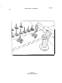
Various others devices are designed and implemented as needed. We use tools, jigs and special
markings for several purposes: to render a task possible (an example is the arm itself), to improve
efficiency (the mechanical screwdriver), and to overcome some of our sensory and mechanical
limitations (the screw dispenser). Currently we have an electrically powered screwdriver, a
pneumatic vise, and an electrically controlled turntable. The screwdriver can be picked up by an
arm and operates in either direction over a range of speeds. The vise can be opened or closed;
soon there will be a way to servo it to a specified opening. The computer can position the
turntable to any rotation (within .5 degrees). As such devices are built, they will be interfaced to
the A-to-D, the runtime programs told how to control them, and the language extended to include
syntax to describe how to use them.
AL resides on two computers: The PDP-10 for all planning, and a PDP-1 l/45 for the execution
of the plans. The former is run as a timesharing computer (under a modified DEC system); the
latter is operated in stand-alone mode under the AL runtime system. Each computer is capable of
generating an interrupt in the other, and the PDP-10 has complete control over the PDP-11
console and unibus. It is not certain exactly-what the minimum runtime computer configuration
will be; we use floating point and memory management, but it is not clear that this is altogether
necessary.
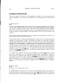
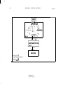
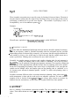
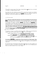
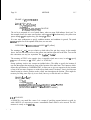
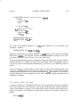
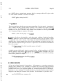
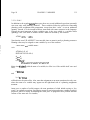
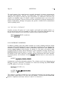
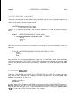
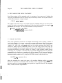
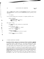
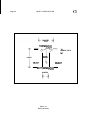
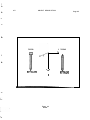
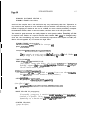
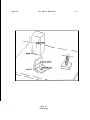
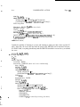
1.3.2 SOFTWARE
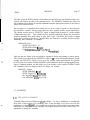
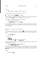
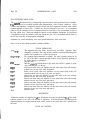
See Figure 1.1 for a picture of the system.
The SUPERVISOR is the top level of AL. It runs on the timesharing computer and provides an
interface between the user and the other parts of the system: 1) listening to the user’s console and
interpreting input in a simple command language; 2) controlling the compiler, starting it and
Page 8
GENERAL SYSTEM OUTLINE
1.3.2
relaying its error messages back to the user; 3) signalling the loader when it is necessary to place
compiled code into the mini; 4) handling the runtime interface to the mini. Each of these
subsidiary modules is discussed below.
The USER sits at a console and makes requests of AL. These fall into several categories:
compilation, loading, execution of programs, debugging of code, requesting of status information,
asking for immediate arm motion, saving and restoring the state of the world at safe points,
requesting explanation of certain compiler decisions. There are two different consoles at which a
user can sit: one is connected to the timesharing computer, through which she can speak to the
supervisor and all the parts of AL residing on the timesharing computer; the other is connected to
the mini, and through it the user can investigate the runtime system and cause modifications.
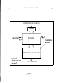
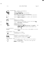
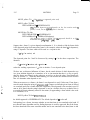
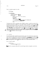
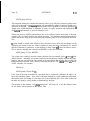
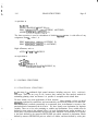
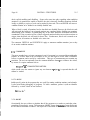
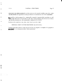
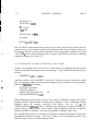
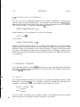
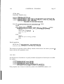
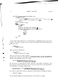
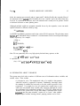
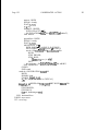
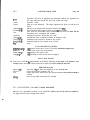
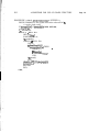
The COMPILER reads AL programs from files (or, optionally, directly from the user’s console)
and produces load modules. The compiler is divided into three phases: The PARSER, the
EXPANDER, and the TRAJECTORY CALCULATOR. The compiler is discussed in detail in
the next section and is pictured in Figure 1.2.
The LOADER takes the load modules prepared by the compiler and enters them into the mini’s
runtime system. Address relocation and linking are done at this time. The loader also sets up the
data area in the runtime interface in the timesharing computer; this data includes output strings,
procedure linkages, and information necessary for diagnostic purposes during runtime. Loading is
often done in a partially incremental fashion, installing new code following previously loaded
code.
The RUNTIME INTERFACE, which resides in the timesharing computer, is charged with
initiating the mini program, fielding procedure calls from the running program to procedures on
the timesharing machine, returning values from these procedures, and fetching values from the
mini for debugging purposes. The interface has the power to interrupt the execution of the
program and to modify the status of the runtime system, for example, by patching in additional
program, or modifying the values of some variables. This allows the user to control the program
through the timesharing computer.
The RUNTIME SYSTEM is the set of programs which reside in the mini. This system includes
kernel programs for time-slice cpu sharing and process control and a set of dynamically created
p recesses. These are of three basic types: a) An INTERPRETER examines the code prepared by
the compiler and executes the numeric computations requested. When a move is to be started, the
interpreter creates a servo for each joint and waits until all these servos are finished. b) A
SERVO handles the motion of one moving joint. c) A CONDITION-MONITOR repeatedly
examines certain conditions (whatever the programmer has specified). If it should discover that
its condition has occurred, it creates an interpreter to take appropriate action. The runtime system
also includes routines for communication with the runtime interface in the timesharing computer.
1.3.2
GENERAL SYSTEM OUTLINE
v I
SUPERVISOR
RUNTIME SYSTEM
A
I
1
DEVICES
CONTROL AND DATA
- - - >
DATA ONLY
Figure 1.1
Overall system
Page 9
Page 10
GENERAL SYSTEM OUTLINE
1.3.2
SOURCE FILE OR TELETYPE
I
1 PARSER 1
LIBRARIES - f-
I
EXPANDER
PLANNING
MODEL
TRAJECTORY CALCULATOR
CONTROL AND DATA
- M m >
DATA ONLY
‘\ \
:1 *r
\ \J
- I
v
LOAD MODULES
Figure 1.2
The ‘AL compiler
Page 11
i
,
1.4 THE AL COMPILER
The AL compiler is built of three parts: the parser, the expander, and the trajectory calculator.
These are depicted in Figure 1.2.
,
1.4.1 PARSER
The PARSER reads source code from either the console or a file. Its purpose is to form parse
trees and do some simple manipulations, such as assigning line numbers, causing listings to be
directed to the appropriate file (if desired), expanding text macros, and keeping a primitive
symbol table. If a syntax error is discovered, it informs the supervisor, which will give the user
several options, including aborting the compilation, making local modifications on the spot, or
switching temporarily to a text editor.
1.4.2 EXPANDER
The EXPANDER shares with the trajectory calculator the responsibility for turning parser
output into code interpretable by the runtime system. Its main functions are to maintain a model
of the expected runtime state at each point in the program and to use this model to resolve a
number of compile-time decisions. The information kept includes planning values, object
descriptions, relations between objects, endpoint constraints on particular trajectories, and much
more. Simple uses of this information include providing the trajectory calculator with essential
data and resolving conditional compilation requests. Beyond this, the expander has principal
responsibility for filling in the details required to turn calls on various high and intermediate
level primitives into runnable manipulation programs. It therefore contains a number of quite
specialized routines with considerable knowledge about the domain of mechanical assembly, as
well as a number of more general mechanisms for coordinating the specialists.
The expander supplies to the trajectory calculator a structure which is very similar to the parse
trees it accepts as input. However, no choices are left; all values have been explicitly specified.
1.4.3 TRAJECTORY CALCULATOR
The TRAJECTORY CALCULATOR takes the expanded code and computes the required
trajectories for the arms. Tables of interpretable code are generated for handling arithmetic and
assignment operations, condition monitoring, and affixment structure building operations (the
runtime system keeps track of physical attachment of objects). For motions, detailed tables are
emitted specifying how each joint of each arm is to behave, what computations to make at runtime for the modification of these trajectories to bring them into correspondence with the current
state of the world (for it happens often that objects are not exactly where they were planned to
be), and what conditions to monitor during the motion.
i
Page 12
THEALCOMPILER
1.4.3
The trajectory calculator also is used to provide information to the expander. For instance, it can
predict the runtime effects of a given modification of a planned trajectory. This information is
useful to the expander for deciding how many different trajectories must be planned for a given
motion request, for estimating the feasibility of a given motion, and for other similar purposes.
There are several errors which the trajectory calculator can detect. A request might take the arm
outside its range, or force a joint to exceed its velocity limits. It may discover that there is a
possibility of collision between the two arms, or between the arm and some object on the table. In
order to carry out these tests, it may request assurance from the user that some object lies within a
certain region, or it may give the user a warning. The world model is used for much of this
calculation. At its discretion, the trajectory calculator may make some critical motions very slow,
so that an impending collision will be detected before it happens.
The output of the trajectory calculator is stored in binary files, for loading into the PDP 11.
1.5 USER FEATURES
AL is designed for users of several varieties; not all of the system is of use to each of them. Some
users wish to make manipulation programs with primitive motions. Others are interested in
. combining several often-used library routines in order to make an assembly program. More
sophisticated users may wish to create library routines and interact with the intracacies of world
modelling. While a task is being executed by the manipulator, a user may wish to monitor its
progress, investigate the internal state of the program, or insert patches in the code to fix errors or
attempt some modification. Thus, the user may have various degrees of understanding of the AL
system, various modes of interaction, and various reasons for using AL.
The bulk of user interaction with AL is during the stage of planning a set of manipulations.
This planning has several phases: initial preparation of the program, removing syntactic ,errors
from the source code, trying the program out, and fixing discovered bugs until the program works
properly. The final stage is the production run of the program, which can occur in a basically
unsupervised mode. During execution, however, it is still possible to interrupt the machine and
find out exactly where it is in the plan and debug it further. This is useful for patching a
program which over the course of a long execution begins to “drift” from reality.
Thus, the user features can be divided roughly into these parts:
1.5.1 PROGRAM FORMULATION
The AL source language is intended to be a clear and complete system in which to express those
manipulations necessary for the correct execution of an assembly task. Writing in AL should be
relatively easy; its inherent structure will be great aid in preparing correct programs.
1.5.1
USER FEATURES
Page 13
Another way in which AL can assist the programmer is that it can read the current location of an
arm and make it available to the programmer. This makes some teaching by showing possible.
One way to put together a simple program is merely to move the arm manually to the different
locations desired, have the system remember those locations, and then type in appropriate motion
commands using these points. In general, a simple “go there” approach fails, because it provides
no way to indicate how fast the arm is to move, what forces to apply, what errors to ignore and
what conditions to monitor. However, AL will allow one to build complete motion specifications
about a skeleton of intermediate points, using textual input to make up for the limitations of
purely tactile input.
1.5.2 PROGRAM COMPILATION
The supervisor is the key to this and the following features; it allows the user to oversee the
progress of the program and fix errors as they arise. There is a simple supervisor language used
to communicate with the AL system. Some of its commands are demonstrated in the sample
dialog given in Appendix I. One of the commands causes compilation to begin; the parser is
directed to read some file. An option is to have console input itself used to enter the source code;
this is especially useful in causing the arm to do something immediately. When the parser finds a
syntax error, it will give an error message, and several options will in general be available. These
include aborting the compilation, skipping to the end of the current statement, editing the line
with the system line editor (after which the entire statement will be reparsed, if possible), and
temporarily switching to a text editor to fix the problem (after which the entire program must be
reparsed).
The compiler detects semantic errors such as generating a move to a point with undefined
planning value, not supplying enough information to a high-level primitive, or attempting to
move the same arm simultaneously in two blocks of code. In those cases where the problem is one
of insufficient information, the expander will prompt for more, and, if possible, continue. The
user may decide not to supply that information, and in that case, the offending statement is
flushed. Some errors are so drastic that they require complete recompilation; the user is always
given the option of switching to a text editor for major modifications.
The trajectory calculator can discover a limited number of errors. These mostly involve motions
beyond the capability of the manipulators involved. Options to the user include making the best
possible legal trajectory, causing the trajectory to be slowed down, and inserting a trajectory
which, when executed, does nothing.
l,-5.3 PR OGRAM EXE CUTION
i
After a program has been compiled, it resides on disk as a load module. Any number of modules
can be loaded together; the principal restriction is that each of them be a “top level” program. As
mentioned earlier, the loader will resolve calls between the large (planning) computer and the
small (execution) computer for those functions which the user has decided require the
computational ability found only on the large computer.
Page 14
USER FEATURES
1.5.3
Execution is initiated by a supervisor command issued by the user. While the mini is executing
the program, the user can cause an interruption and examine values within the runtime system,
and modify them if he wishes. It is also possible to examine the code generated by the compiler
and modify it, but this is most likely only of interest to system programmers. Sizable patches
require recompilation. The programmer (or, at this stage, an operator) can continually examine
the status of the runtime system by means of the mini’s console. Values of variables can be
examined and changed, and individual processes can be interrupted without interfering with
other concurrent processes.
Sometimes hardware difficulties will cause abrupt termination of the program; these often are due
to runtime trajectory modifications overstraining the hardware. After issuing an error message to
the user, the system behaves just as it would should it have been interrupted manually. It is
possible, during one of these “breaks”, to request that the entire world be saved. This causes all
runtime values to be written out into a safe place, along with the current attachment structure and
the current program counters. This feature allows the debugging of the task to stop temporarily
and to be resumed later. More importantly, it is possible to create a “safe point” in the code, SO
that if an error should occur later, it is possible to back up the program to a point at which
everything was still working.
Programs which have been completely debugged can be “unloaded”, that is, saved in a compiled
form for execution any time in the future.
Page 15
CHAPTER2
THEBASICSOURCELANGUAGE
AL has several levels of complexity. We will start by discussing the basic source language; this
covers enough to write substantial manipulator programs, but has none of the high level
capabilities mentioned in the section on goals and philosophy.
2.1 DATA STRUCTURES
2.1.1 DA TA TYPES
In this section we present the data. types available in AL, Roughly speaking, a data type is a kind
of numeric object. For example, FORTRAN has the data types INTEGER and REAL. A
variable is an identifier of some type which can take on values. In AL, each variable must be
&clar&, that is, one must state what its type is, somewhere in the program before it is used.
There are several reasons for this: It allows the compiler to detect spelling errors, and it allows the
same name to be used in different blocks without conflict. AL uses ALGOL block structure,
which means that all variables declared between a particular BEGIN and END are accessible only
to code which appears between the same BEGIN-END pair. The exact details of block structure
are discussed in the section on control structures.
2.1.2 ALGEBRAIC DATA TYPES: SCALARS
Algebraic data types are the most familiar. They represent measurements in the real world. An
algebraic variable can assume a value by means of the assignment statement, which consists of
the variable name, a left arrow (“t”), and an expression which has the correct type. When an
assignment statement is executed, the expression on the right hand side is evaluated, and that
value replaces the old value of the variable on the left hand side.
The most elementary data type is scalar, which is internally represented as a floating-point
number. Scalars are used for dimensionless quantities, like the number of times some operation is
to be repeated, or to implement a signal which becomes positive when some critical operation is
finished. The arithmetic operations available on scalar variables are addition, subtraction,
multiplication, and division; the arithmetic operators which perform these operations are the
standard: +, -, : {, /. As is usual in algebraic languages, the first two have lower precedence than
the others.
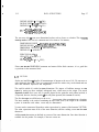
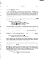
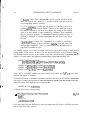
Scalar constants are written as (base ten) numbers, either with or without a decimal point and
fractional part, Here are some examples of declarations and applications of scalar variables:
DATA STRUCTURES
2.12
SCALAR sl, s2;
(Our examples will use a mnemonic scheme for naming variables to clarify the
type of each entity. Please understand that identifiers can be any string of
letters, of any length, and that AL does not distinguish between upper and
lower case. Cur/y brackets are used in AL to enclose comments.)
sl +2;
s2 + 3.74;
s 1 c s2 <t (s 1 - 3.2);
It is often desirable to give some physical meaning to scalar variables. AL provides for scalars
with the dimensions time, distance, angle, and mass in addition to “simple”, dimensionless scalars.
Time constants are just like simple scalar constants, except they are multiplied by the reserved
word set (for “seconds”). The other reserved words related to these dimensioned scalars are CM
(centimeters), deg (degrees) and gm (grams).
Dimensioned scalars are used exactly in the same way as simple scalars; the only difference is that
AL will check that addition and subtraction are only performed on compatible values. AL
performs dimension checking for each arithmetic operation and each assignment. Addition,
subtraction, and assignment require exact dimension match, but if match fails and one of the two
arguments is simple (no dimension), it will be converted. Thus it is always legal to use simple
scalars where dimensioned ones are expected. Multiplication and division do not require
dimension match; they produce a result of a dimension usually different from that of the
arguments; this new dimension is then propagated through the expression. In this way,
intermediate results can be of dimensions not declared. This causes no problem unless one tries to
use such results in an assignment.
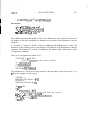
Here are some examples of dimensioned scalars:
TIME SCALAR tm 1, tm2;
MASS SCALAR msl;
ANGLE SCALAR theta, phi;
tml t 3 : : SEC;
ms 1 c msl + 2.2 : t CM;
msl t msl +-2.2;
.
(The constant 2.2 will be automatically converted to grams.)
theta c 90 ::( DEG;
tm 1 c tm2 : ( 5.5;
phi t theta : c 4 i:: DEG;
(This is a mistake; the right side has dimension angle,:(angle)
If the user feels more comfortable with inches or pounds, it is quite easy to write macros which
will make such usage possible. This is best demonstrated by example:
I
L
L
DATA STRUCTURES
2.1.2
Page 17
DEFINE INCHES = “(2.54 tg CM)“;
DEFINE FEET = “(12 8 INCHES)“;
DEFINE LB - “(GM : r 1000 / 2.2)“;
ms 1 t 22:sLB; (= 1 OOO?::GM)
ds 1 t &lFEET; (- 3+12::2.54,::CM)
The user may wish CO create new dimensioned scalars, such as forces or velocities. This is readily
done by means of the dimension statement and a few macros. For instance,
DIMENSION FORCE - DISTANCE::~MASS/(TIME::~TIME);
DEFINE DYNES = “(GM:::CM/(SEC::SEC))“;
DIMENSION VELOCITY = DISTANCE/TIME;
DEFINE CPS = “(CM/SEC)“;
FORCE SCALAR fol;
VELOCITY SCALAR ve 1;
vel + 2.3::CPS;
fol t vel I:< 3 ~:f GM / (8.4 !:I SEC);
Please note that the DIMENSION statement and macros follow block structure; it is a good idea
co put them in the outermost block.
2.1.3 VECTORS
Scalars are insufficient CO describe all measurements of interest to the user of AL. We turn now co
ocher algebraic data types. They are syntactically much like scalars: they are declared and can
enter into arithmetic expressions and assignments.
The world in which AL resides has three dimensions. We impose a Euclidean structure on that
space by setting up three cardinal, orthogonal axes, which meet at the origin. The actual
alignment of these station axes will, in general, depend on the particular work station involved; it
is expected, however, that the positive 2 axis will point upwards (this is not at all crucial).
The first data type we will discuss is the vector. It represents either a translation or a location.
The latter meaning is the result of translating the null vector, that is, the origin of the coordinate
system. As is the case with scalars, vectors may be dimensioned.
Vectors can be constructed from three scalar expressions by means of the function VECTOR,
The scalar expressions must all be of the same dimension, and the resulting vector has that same
dimension.
Addition and subtraction are defined on vectors of the same dimension. One other function is
available: the dot product. For example, if the two vectors are:
DATA STRUCTURES
v
2.1.3
l-VECTOR(x l,yl,zl) and v2=VEClUW2$2,~2),
then we have
s 44 vl - VECTOR(u:x 1, ssy 1, s:szl)
vl +v2= VECTOR(x 1+x2, yl+y2, z1+z2)
vl - v2 - VECTOR(xl-x2, yl-y2, zl-~2)
v 1 . v2 = x l::ex2 + y l::sy2 + zl::cz2 .
Thus, addition and subtraction produce vectors in the familiar way; the dot product is the sum of
the products of the three components; its dimension is the product of the dimensions of the two
arguments.
It is possible co “stretch” or “shrink” vectors by multiplying and dividing them by scalars. The
dimension of the resulting vector is the product or the quotient of the dimensions of the two
arguments. The magnitude of a vector is calculated by the function ABS, which returns a scalar
of appropriate dimension.
There are several predeclared vectors in AL:
VECTOR X, Y, 2, NILVEC;
(There are predeclared and have values as follows)
X t VECTOR(l,O,O);
Y t VECTOR(O,l,O);
Z t VECTOR(O,O,l);
NILVEC t VECTOR(O,O,O);
The components of a vector can be easily extracted as the dot product of the vector with X, Y, or
2. Here are examples of other vectors:
VECTOR v 1;
DISTANCE VECTOR dv 1, dv2;
SCALAR sl;
DISTANCE SCALAR dsl, ds2-;
dsl t 4 I:( CM;
sl t -2;
dv 1 t VECTOR(s1, 2.3, dsl);
(This is a distance vector; the simple scalars get converted.)
~1ls2 t dv 1 . Y; (So &2 gets 2.3::CM )
v 1 t dv 1 / ds2; (So vl + VECTOR(-2/2.3, I, 4/2.3).)
dv2 t ds2 $:a v 1; {So v2 + dvl)
s 1 t ABS(v 1);
DATA STRUCTURES
2.1.4
Page 19
2.1.4 R OTA TIONS
The rot, our next data type, represents either a rotation or an orientation. The latter is the result
of applying the rotation CO the station coordinate system. Rots are internally stored as 3x3
matrices, which operate on column vectors in the usual way. Thus rots can operate on vectors
and move them around the origin (without changing their length); they can also operate on other
rots (by matrix multiplication). To rotate a vector (about the station origin), multiply the vector
(on the right) by the rot (on the left). To compose rots, multiply them together; the one on the
right will be applied first.
A rotation can be constructed with the function ROT, which takes two arguments: a simple vector,
which is co be the axis of rotation, and an angle, which is the amount Co rotate. The direction of
rotation follows the right-hand rule; a rotation of 90 degrees about the X axis moves the Y axis
into the Z axis. This turns out Co be a general representation far easier Co write and understand
than raw matrices. We hope the following examples will serve Co clarify the proper use of rots:
ROT r 1, r2, r3;
ANGLE SCALAR alpha, beta, gamma;
rl t ROT(X, 90::cDEG);
v 1 t r 1 ::: Z;
(VI gets 2 rotated 90 degrees about X, so VJ + VECTOR(O,-l,O).)
r2 t ROT(Y, 45::cDEG);
r3 t r2 0 rl;
(Thus, r3 means: rotate first 90 degrees about the X axis, then 4S about the
original Y axis.)
r 1 t ROT(X,alpha);
r2 t ROT(r laY,beta);
r3 t ROT(r2:rZ,gamma);
r4 t r3 ::t r2 0 r 1;
(r4 is then a rotation with this meaning: Rotate by alpha degrees about the X
axis, then by beta degrees about the neru Y axis, then by gamma degrees about
the doubly new Z axis.1
The null rot, which has no effect,-is called NILROT.
2.1.5 FRAMES
The next data type is the frame, used CO represent a coordinate system. It has two components: the
location of the origin (a distance vector) and the orientation of the axes (a rot). Frames are
typically used CO describe objects; one can specify locations of features on an object by translating
them from the object’s origin.
-
There are several predeclared frames in AL. Station is the frame which represents the work
station’s frame of reference. Each hand available to the system also has a frame variable, whose
value (continually updated) is the position of that hand. Currently, there are two such frames:
J&OZU and blue. Each arm has a rest, or park position, known as ypark and bpark.
DATA STRUCTURES
2.1.5
A frame may be constructed by a call on the function FRAME:
I
FRAME fl;
DISTANCE VECTOR dv 1;
ROT rl;
f1 + FRAME(rl,dvl);
The two arguments are a a rot (for the orientation) and a distance vector (for the position). To
extract the rot or the vector from a frame, use the functions ORIENT and LOC, respectively. T O
find where a vector goes if its base is moved from the station Co the coordinate system of some
frame, “multiply” the frame (on the left) by the vector (on the right). To translate a frame by
some distance, simply add a distance vector Co it.
Often one wants CO construct a vector which is oriented like some vector (for example, the X
vector) in some frame, say FL The with respect to operator WRT gives exactly that; one writes
4
(X WRT Ft). Examples of this and other constructs pertaining to frames follow:
FRAME fl, f2;
f 1 t FRAME(ROT(Z,SO:::DEG),‘L::~X);
{fl sits 2 centimeters from the station, in the X direction. Its coordinate system
has X where the station’s Y points.)
v 1 t X WRT f 1; (This evaluates to VECTOR (O,l,O).j
f2 t f 1 + v 1; Cjust like fl, but with origin at (Z,J,O).)
v 1 t f 1 : g Y; (This evaluates to VECTOR (I,O,O)J
v2 t v3 WRT M;
(This is equivalent to (12~3) - LOC(fz), and also to OR IEN T(f2):w3.}
’
2.1.6 PLAIVE S
Next we have the plane, used Co separate space into regions and Co specify the locus of searches.
Planes are formed by use of the function PLANE, which takes two distance vectors as arguments:
The plane is co pass through the first vector, and the outward-facing normal to the plane is in
the direction of the second vector. Thus PLANE(X,Y) is a plane parallel to the X-Z plane,
translated from it by one centimeter in the X direction.
Planes are internally stored by four numbers: the first three are an outward-facing normal, and
the last is the opposite of the distance from the plane CO the origin.
Each plane dtvides space into three regions: inside, on, and outside the plane. (The last set
contains all points on the same side as outward-facing normal.) To find out in which region a
point (represented by a distance vector) lies, extract the inner product of the vector with the plane.
Its value is a distance scalar whose absolute value is the shortest distance from the vector co the
plane, and whose sign is negative if the vector is inside the plane, 0 if the vector is on the plane,
and positive if the vector is outside the plane. The arithmetic operator for the inner product is a
DATA STRUCTURES
Page 21
dot; the plane may appear on either side of the dot. If the plane P has an internal representation
consisting of four numbers A, B, C, and D, and V - VECTOR(X 1,Y 1,Z 1), then we have:
p . V = A::tX 1 + &X2 a C::<X 3 + D
Other operations available on planes are translation (by adding a distance vector) and rotation
(by multiplying by a rotation). To get the outward-facing normal of a plane, use the function
NORMAL, which takes a plane argument and returns a distance vector.
Examples:
PLANE pi, p2;
p 1 t PLANE(VECTOR(O,O,O),Z);
(This is the surface of the station)
v l t NORMAL(p1 + ~2);
(No matter what v2 is, vl will get 2)
ds 1 t p 1 . VECTOR(2, -13.2, 32.3);
(ds1 gets 32.3+cm]
I
2.1.7 TRANSFORMS
The last of the algebraic data types is the trans, which stands for “transform”. It is an operator,
Chat is, a function, which can operate on vectors, frames, and planes. The application of a trans
Co any of these is written as if it were a multiplication, with the trans on the left. To compose
several transes together, “multiply” them, with the one CO be applied first on the right.
The trans itself is defined as a function which can take objects in one frame of reference into
another. One can construct a trans by use of the function TRANS:
TRANS cl;
VECTOR v 1;
ROT rl;
.
cl c TRANS(rl,vl);
The two arguments are a rotation the rotational part and a vector (the translational part). The
application of a trans CO a vector, frame, or plane first rotates that object according CO the rotation
part (rotating about the station origin), and then translates the result according Co the translational
part.
-
c
II
-
Transes, like vectors and scalars, carry dimension. The rule is that when a trans is applied CO a
vector, they must agree in dimension; the resulting vector is of the same dimension. When a trans
is applied co a frame, it must be a distance trans. When a frame is used in a context demanding
a transformation, it will be understood as a shorthand for the distance trans leading from the
station. When transes are composed, they must agree in dimension.
DATA STRUCTURES
2.1.7
There is another convenient way to specify a trans: by forming it from two frames. The trans is
then the function which takes the origin of the first frame across to the origin of the second,
performing a rotation first to get the axes aligned. This method of specifying a trans is
accomplished by use of the arithmetic operator “+“.
Examples:
TRANS t 1, t2;
t 1 c f 1 -+ f2; (Thur rlq - f21
vl + tl :5 v2;
t2 t tl : : tl;
v 1 c f 1 : i v2; (Equivalent to (STA TlON-+fJ)w2]
The null trans, equivalent to TRANS(NILROT,NILVEC) is called NILTRANS.
2.1.5 PLANNING VALUES
AL works under the fundamental philosophy that arm motions should be planned in advance.
Since an arm trajectory cannot be calculated reasonably unless the end-points (and any specified
_ intermediate points) are known fairly accurately, it is necessary that the compiler maintain for
each variable a planning value which may be used in the case that the variable enters into a
motion specification. Planning values are discussed in more detail in Section 3.2.
Essentially, the compiler attempts to assign to each variable a planning value for each statement in
the program. Initially, the planning value of each variable is “undefined”; one of the ways that a
planning value can be assumed is through an assignment statement. The compiler evaluates the
planning value of the right hand side, and this becomes the new planning value of the variable
on the left. Propagating the planning value across loops is complicated; in the case that the
variable can take multiple values, the compiler either sets the planning value to “undefined” or, as
AL becomes more advanced, maintains parallel “worlds” in which each planning value is
monovalued.
Variables can attain different values at run-time than their planning values when some realworld measurement is taken and the result used in an arithmetic expression. The most common
example of this is that the frames yellozu and blue are always kept accurate at run-time by
feedback from the arm hardware, so their values will in general differ from those planned.
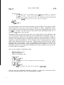
2.1.9 ARJTHME TIC
Here is a summary of the arithmetic expressions available. They are grouped by the type of their
values. These abbreviations are used: ‘s’ = scalar, ‘v’ - vector, ‘r’ - rot, ‘f’ - frame, ‘p’ - plane, ‘t’ =
trans.
r
DATA STRUCTURES
2.1.9
scalar
9 + s
s - s
s * s
s / s
v . v
P
v
l
V
l
P
Page 23
expressions:
scalar addition (commutative)
scalar subtraction
s c a l a r mul tip1 ication ( c o m m u t a t i v e )
scalar division
dot product of two vectors (commutative)
signed distance from vector to plane (see discussion
above on planes)
signed distance from vector to plane (see discussion
above on planes)
vector
s * v
v.1 s
v + v
expressions:
dilation of a vector
contraction of a vector
v e c t o r a d d i t i o n ( t r a n s l a t i o n o f t h e f i r s t v e c t o r by
the second) (commutative)
vector subtraction
V - v
rotation of a vector
r * v
transformation of a vector
t * v
v WRT f
a v e c t o r o f l e n g t h ABS(v) r o t a t e d i n t o f ’ s s y s t e m ; I ike
ORIENT(f)*v: t h a t i s , a v e c t o r i n s t a t i o n
coordinates which looks to the station as v
d o e s t o f.
rot expressions:
r*r
composition of two rots (first to be applied is on the
r,ight)
frame express i ons:
f + v
translation of a frame
t * f
transformation of a frame
plane expressions:
translation of a plane by a vector
P + v
rotation of plane (about station origin)
r * P
t r a n s f o r m a t i o n o f a p l a n e b y a trans
t*cp
trans express i ons:
f -) f
transformation which leads from the first frame to
the second
compos i ng- two transes.
t * t
The one on the right will
o p e r a t e first.
Page 24
DATA STRUCTURES
PREDECLARED CONSTANTS AND VARIABLES:
n is simple, has value = 3.14 159...
STATION is a frame which has standard station coordinates. (constant)
BLUE is the location of the blue hand.
YELLOW is the location of the yellow hand.
BPARK is where the blue hand parks. (constant)
YPARK is where the yellow hand parks. (constant)
X is VECTOR(l,O,O).
Y is VECTOR(O,l,O).
2 is VECTOR(O,O,l).
NILVEC is VECTOR(O,O,Oj.
NILROT is ROT(X,O::aDEC).
NILTRANS is TRANS(NILROT,NlLVEC).
EXTRACTION FUNCTIONS:
LOC(FRAME) is a vector whose value is the location of the frame.
ORIENT(FRAME) is a rot whose value is the orientation of the frame.
NORMAL(PLANE) is the outward facing normal vector of a plane.
2.1.10 SOME EXAMPLES OF ARITHMETIC EXPRESSIONS
In the following examples, assume these declarations:
FRAME fl, M, etc;
VECTOR vl, v2, etc;
SIMPLE sl, ~2, etc;
ROT rl, r2, etc;
PLANE pl, p2, etc;
f 1’S unit Y vector, in station coordinates:
fl::(Y
f l’s 2 vector as seen from f2:
(f2 + f 1) $3 2
A vector pointing in same direction as f l’s X coordinate:
X WRT fl
v 1 rotated 90 degrees about the station’s 2 axis:
ROT(Z,SO:zDEC)::~v 1
fl’s Y-Z plane:
PLANE(LOC(f 1),X WRT f 1)
2.1.9
2.1.10
DATA STRUCTURES
Page 25
A plane 3 centimeters above the station:
PLANE(VECTOR(0,0,3),2);
PLANE(3::ZZ);
An identity with WRT:
v 1 WRT f I = ORIENT(f 1):::v 1 = (f l::tv 1) - LOC(f 1)
2.2 MOTIONS
Motion statements are at the heart of AL; it is by them that all manipulatory work is done.
2.2.1 COMPILE-TIME AND RUNTIME CONSIDERATIONS
All motion statements cause the compiler to make some plans which will eventually be executed.
Those motions which depend on the value of some frame expressions for intermediate and final
position will be planned using the compile-time planning values for all relevant expressions. This
can lead to inaccurate plans, since at runtime, some of those expressions might have different
values. An example is an expression involving the location of the arm; the variables yelloru and
blue are always kept accurate at runtime by reading the arm locations. Since every arm motion
must begin at the current arm position, this is an implicit parameter to the motion specification
which may not agree with its planning value. This is a special case of a general phenomenon:
objects are seldom exactly where they were planned to be, and the runtime value of their frames
will very likely be based on the position of the hand after it successfully locates the object by
sensory feedback.
Thus it becomes necessary that the runtime system adjust all trajectories immediately before they
are executed. Adjusting a trajectory is less time-consuming than the original calculation; it makes
sense to adjust before each repetition of a motion, whereas it would be a waste of computer time
to recalculate trajectories that often. Immediately before the arm starts moving on a trajectory,
then, the plan is modified to bring it into line with current values of frames. If there is any
discrepancy between the runtime and compile-time understanding of where any frame is, the
servo will try to place the arm in the right place nonetheless.
.
There are limits to the proper use of this feature; if the planning value is seriously in error
(which can happen if the error is but a few centimeters, depending on the arm being used and its
configuration), then the attempt to make last-minute corrections might overstrain the arm or
impair response to directional forces. It is the user’s responsibility to foresee large discrepancies in
the planning value and to program in a condition to select one of several possible moves.
Hopefully, this will be seldom needed.
After a motion has been completed, the new location of the hands will be read, and that will
Page 26
MOTIONS
2.2.1
determine the new value for yellow and blue, as well as for any frames which might be affixed to
them. For the moment, we will ignore affixments; they are discussed in great detail later.
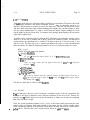
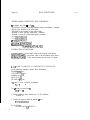
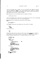
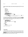
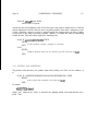
2.2.2 SIMPLE MOVES
In this section we will discuss motions which are to be executed on only one arm. Let us start
with an example:
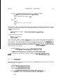
FR AM E frobgrasp, swing 1, swing2;
‘MOVE yellow
TO frobgrasp
VIA swingl, swing2
This example demonstrates the general syntax; the reserved word MOVE is followed by the name
of the arm to be moved and a set of clauses, each beginning with a reserved word (here the words
TO and VIA). There is no punctuation necessary at the end of a clause. The arm is expected to
travel from its current position (wherever that is planned to be) to the final position (frobgrasp),
passing through the intermediate positions (szuingi and szuing2). A smooth trajectory for the
motion will be computed by splining together polynomial segments (usually third degree,
occasionally fourth) separately for each arm joint. This trajectory calculation is somewhat timeconsuming and is done completely at compile time.
Certain things must be specified for any move. First is the arm which is to be moved. It is
named by an arm frame (yellozu or NW); other ways of specifying the arm will be mentioned after
the formal idea of affixment has been presented. Next, the destination frame must be specified.
“TO frobgrasp” means that at the end of the motion, the position of the arm should coincide with
the position of frobgrasp. There is a notational convenience for destinations: They can be
specified in terms of where the arm is at the start of the motion. The symbol for this is “QP”
(sometimes pronounced “grinch”), that is, 4~ is a frame which has the location and orientation of
the arm at the start of the motion. Thus,
MOVE yellow TO QD + &CM
will move the arm 1 centimeter in Z above its starting place.
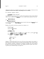
2.2.3 cOlJDlT/ON MONITORS
During the course of an arm motion, it may be desired to monitor some condition or set of
conditions in order to prematurely stop the motion or inform some parallel process that a
condition has occurred. The conditions which may be checked are results of measurements, such
as time or force checking, and events, which are signals that can be explicitly sent by other
simultaneous processes. Events will be discussed in subsection 2.5.4; for the time being,
assume that the only conditions which may be checked are measurement conditions. Here is an
example which contains some condition monitors:
‘.
2.2.3
MOTIONS
Page 27
SCALAR warning;
VECTOR v 1;
MOVE yellow
TO ypark
ON DURATION >, 3:::SEC DO warning c 1
ON FORCE(v1) 1 18::{OZ DO STOP (Stops the arm}
This motion has two separate and independent condition monitors; the first wilt trigger if the
motion takes longer than three seconds, and the second will trigger if the force on the hand, as
measured along vector vl, exceeds 18 ounces. (Assume we have a macro which translates ounces
into units of force.) The conclusion of a condition monitor, the code which will be executed if the
monitor triggers, is one statement prefaced with the reserved word DO.
‘,
i
A condition monitor has two states: enabled and disabled. Generally, a condition monitor will be
enabled as soon as its motion statement is started, and it becomes disabled when the motion ends.
As soon as a condition monitor triggers, it becomes disabled unless it becomes explicitly reenabled.
Reenabling is done by executing the statement ENABLE ‘within the conclusion.
In order to enable or disable some arbitrary monitor, it is necessary to give it a name; this is done
by putting a label immediately before the word ON. A label is an undeclared identifier followed
by a colon. Thus we could write:
MOVE blue TO frobgrasp
test 1: ON DURATION 1 3:::SEC DO DISABLE test2
test2: ON TEMPERATURE < 30 DO STOP
Thus, test2 is only performed for the first three seconds.
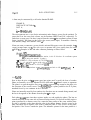
Occasionally one wants to write a condition monitor which is initially disabled and becomes
enabled later. This is accomplished by putting the word DEFER before ON:
fudge: ON temperature > 400 DO
BEGIN {Keep shouting until someone hears.)
WRITE(“BURNINC”);
STOP OVEN; (Pretend rue have a device OVEN)
EN ABLE (This reenables fudge}
END
taste: DEFER ON cooked (This is an event.} DO DISABLE fudge
ON DURATION > 30::?MIN DO ENABLE taste
It should be noted that this ability to enable and disable monitors explicitly is a non-structured
construct; using it can lead to unintelligible programs. In any case, scope rules must be observed;
it is not legal to enable or disable monitors across different MOVE statements. This means that
two motion statements which happen to be simultaneously executing (we shall see how to do this
later, in subsection 25.2) cannot interfere with each other’s condition monitors,
Boolean combinations of conditions are not allowed. Some of the continually measured functions
Page 28
MOTIONS
2.2.3
which may be tested are force along a vector, (FORCE(V)), force about an axis (TORQUE(V)),
time since beginning of motion (DURATION), and the force between the fingers (SQUEEZE).
One standard event is testable: ARRIVAL. This event occurs when the motion terminates due to
having reached its destination. It does not become true if the arm stops for reasons other than
normal arrival at the destination; STOP does not trigger it.
The, conclusion of a condition monitor may be any statement, including an entire block. The only
restriction is that if a motion statement is the only statement in the conclusion, it must be
surrounded by BEGIN and END. (This is necessary at times to prevent ambiguity.) The compiler
will complain if you try to embed a motion statement inside another if the result implies
simultaneous motion statements for the same device.
The existence of condition monitors raises this question: When is the motion really finished? It
can happen that the arm itself has stopped, but some monitor has triggered, and its conclusion is
still busy being executed. The rule is this: the motion is declared done when all the joints of the
arm are stopped, and all monitors are either disabled or not currently triggered. Any monitors
still enabled, but not triggered, are disabled at the time that the motion is declared finished.
The user must be aware of some timing considerations. Firstly, measurements like FORCE,
DURATION, and SQUEEZE are not really computed continually; there is a process which makes
a measurement and then lies dormant for a while (on the order of twenty milliseconds) before
again making a measurement. Thus, monitors do not trigger immediately when a tested condition
+comes true. Secondly, when a monitor triggers, any initial statements of enabling or disabling
are done immediately, but any arithmetic is scheduled to be done at some point in the near future.
Therefore it is not possible to guarantee that a critical computation happen immediately. If the
user desires, he may use the word CRITICAL at the start of the conclusion, and UNCRITICAL
at the start of that code which need not be guaranteed immediate execution. Only one occurrence
of CRITICAL, at the very start of the conclusion, and only one occurrence of UNCRITICAL are
allowed. AL automatically assumes CRITICAL before initial statements of enabling and
disabling, and UNCRITICAL immediately following. An example:
ON DURATION 142:SEC DO
(Tested frequentiy}
BEGIN
Qssumed CRITICAL)
ENABLE goodguy;
@ssumed UNCRITICAL)
t + 3;
END
ON SQUEEZE 2 lOb:jOZ DO
(Tested jrequently)
BEGIN
CRITICAL; ’
(Overrides defaults)
{Wi&l be done immediately)
t i- 4;
UNCRITICAL;
(End of critical region)
DISABLE goodguy;
{Done soon)
END
f
:, .
c.
L
2.2.4
‘L.
2.2.4 FORCE DURING A MOTION
L
iL
MOTIONS
Page 29
To make the arm compliant to external forces along some directions or about some axis it is
necessary to specify the appropriate modes of freedom. Because AL works in three-dimensional
space, it only makes sense to specify at most three orthogonal directions and three orthogonal axes.
In addition to being compliant along degrees of freedom (whether translational or rotational), it is
also useful to apply a fixed force along some of these degrees. Then pure freedom reduces to
application of zero force.
For example, suppose the arm is on the surface of the station; we wish to apply a force of 10000
dynes directly downward (the negative 2 direction) while allowing the arm to comply to any
horizontal force. This is how we would write such a motion:
MOVE blue TO @ (moues nowhere)
WITH DURATION - IO&EC {give it Jome tine.)
WITH FORCE = - lOOOO::<DY NES ALONG Z OF station
WITH FORCE = 0 ALONG X, Y OF station
,
,
ik
,
L
,
t
This example illustrates several conventions. A translational degree of force (or freedom, if the
amount of force is zero) is specified by the word ALONG followed by a list which can only
contain the vectors X, Y, and Z, followed by the word OF and the name of the frame which
specifies the coordinate system in which the cardinal axes are to be understood. The amount of
force must be in force units, which are of the scalar dimension mass:::nistancel(time~:;time); we have
assumed in the example above that DYNES is a macro which expands to correct units.
Rotational degrees of force are written in much the same way1 the axes are specified ABOUT a
combination of X, Y, and Z OF some frame, like this:
WITH FORCE = 5000:::DYNES ABOUT Z OF e
i
Ii
i
L
i
,
c
L
(A p/dies a torque about the Z direction of the hand.)
During a motion which has only translational force specifications, the orientation of the hand will
remain as planned, but the location will comply with the specified force. During a motion which
has rotational degrees of force, the orientation of the hand will vary from that planned in accord
with the specification and whatever external forces are encountered.
It does not really make sense to have a force in the nominal direction of motion, but there is
neither a compile-time nor a runtime check to catch such usage. If it happens, the arm could go
into oscillation.
Actqally, not all of the full power of force specifications will be available in the first versions of
AL. In particular, rotational specifications will be handled roughly or not at all. Another future
embellishment will be to allow the directions of force to vary during the motion; this is useful for
such tasks as turning a crank. For example, the following will eventually be available:
MOVE yellow TO frobgrasp
WITH FORCE = SIN(DURATION:::DEG)::O0000::~DYNES
ALONG Z OF o;
MOTIONS
Page 30
2.2.4
This specifies a varying amount of force along a varying direction: “et” means “the current location
of the hand, as it changes during the motion.”
Especially at first, some of the force control will be prepared by the compiler, not calculated
during the arm motion itself. Therefore, if the runtime values of the endpoints of motion are
significantly at odds with their planning values, application of force may go awry.
2.2.5 DE PR OACHES
Many objects have shapes which necessitate care as the arm approaches them or departs from
them: AL supplies a method for insuring that every time the arm approaches a frame, it will pass
through an associated spot first, and every time it leaves that frame, it passes once again through
the same spot. The “spot” is termed a neproacA (from departure and approacA); it is a
transformation to be applied to the frame involved in order to discover the appropriate place
through which to pass. The fact that a trans is used implies that the deproach point will move
about with its frame. It also means that the location of the deproach point is relative not to the
origin of the frame, but rather to the point in frame coordinates to which the motion leads. For
example, the deproach transformation of the station is TRANS(VECTOR(O,O, I O:::CM),NILROT).
If the arm is to go to, say, the point VECTOR(3,1,4)+station using station’s deproach, then it will
first go through VECTOR(3,1,14). This has the effect of preventing the arm from going through
_ the surface of the station.
The deproach of a frame is specified by means of an assertion. Without going into full detail on
assertions (which will be covered in detail in Section 3.4), we give some examples:
ASSERT FORM(DEPROACH, station, TRANS(NILROT,VECTOR(O,O,lO:::CM));
(This is preasserted and need never be included.)
ASSERT FORM(DEPROACH, frob, TRANS(ROT(X,SO:sDEG),VECTOR( l,O,O)));
(Whenever you go to frob, go through a point 90 degrees about frob’s X axis
from a spot one centimeter in X from the nominal arrival point.)
Note that since deproaches are transformations, they have the power to include rotations. These
are considered to be rotations about the origin of the coordinate system involved; the rotation
occurs, as usual, before translation. The use of- rotations is of marginal use, but is included for
completeness.
The deproach points of the departure frame and the arrival frame are used as implicit VIA
points for any motion, except when the destination is “e” or there is an overriding deproach
clause-in the motion statement. Here are some examples:
MOTIONS
2.2.5
Page 31
MOVE yellow TO s; (No dsparture or approach point used)
MOVE yellow TO frob
WITH APPROACH = NILDEPROACH;
(The default departure (rclhich depends on the last motion made by
yellow) is used, but no npproach point is desired.)
MOVE blue TO frob
WITH DEPARTURE = NILDEPROACH
WITH APPROACH = DEPROACH(frobgrasp);
(No departure point is desired, but the approach should be as if the
destination were frobgrasp, not frob.]
Suppose that a frame f is given deproach transformation d. It is desired to find the frame which
is the deproach point from some other frame h (for example, where the hand is, for departure),
using f’s deproach. The frame which will be used as a via point is this:
f Q d ,: (f -$ station) : I h
.
The deproach point for f itself is discovered by setting h = f in the above expression. The
identities
(f + station) : : f = station, and a I:( station = a
reduce the resulting expression to f ::: d; this is therefore f’s own deproach point.
We have not yet discussed affixment of frames, but the actual decision of which deproach to use
in a given situation depends on it somewhat, so let us just mention that there is a way to specify
that two frames are affixed, so that whenever on moves, so does the other. Exact details are
given in Section 2.3. With this understanding, we can describe the method used to describe
how AL determines what deproach to use:
i.
When an arm moves to a frame, t-he frame’s own deproach is used, if it has one. If not, then a
search is made along the string of affixments-(that is, frames to which the given frame is affixed
are searched) until one is found which has a deproach. That deproach is the one that is used. If
none at all is found, then the station’s deproach is used as a default. (One way to think of this is
to consider all frames ultimately affixed to the station.) In approaching a frame which is the result
of a calculation, as in
MOVE yellow TO frob + VECTOR(O,O,l)
,
the default approach is NILDEPROACH. The default deproach of Q is also null.
In departing from a frame, it matters whether or not that frame is now attached to the hand. If
not, then the same algorithm used for finding departure is used for approach. But if the frame
has been detached from some erstwhile mother and is now attached to the hand, then its old
Page 32
MOTIONS
2.2.5
mother’s deproach is used (and if there is none, the same search is made). Thus, a frame attached
to the hand still has some “memory” of its previous state of attachment.
2.2.6 OTHER MOTION CLA [JSES
Here we describe some of the other additional clauses that may be associated with motion
statements. The first is WITH DURATION, which allows the user to specify the timing for the
motion. One can use 1,=, or < for duration control. The first is used to guarantee that the motion
take a certain amount of time, that is, it guarantees that the motion will be slow enough so that all
the time is used. The second is rarer; it is used when the exact time is somehow critical. If the
compiler thinks that the arm cannot move fast enough, it will complain. The third form is
included primarily for completeness; once again, it can cause the compiler to complain. In the
absence of any timing specification, AL will compute the least time which will allow the particular
arm being used to move most efficiently.
VIA is used to name desired points along the trajectory. In its simplest form, the VIA clause
contains merely a list of frame expressions, such as in this example:
MOVE yellow TO finalpoint
VIA intl, int2 + VECTOR(O,O,l), int3;
-The motion will be planned to go from the current location of the yellow arm, through a
departure point (if there is one), through each of the intermediate frames, through the approach
point (again, if there is one), and finally to arrive at finalpoint.
At each of the intermediate points, it is possible to specify the velocity to be achieved at that point
(in terms of a velocity vector) as well as upper or lower bounds on the time used to reach this
frame from the previous one on the list. Here is an example demonstrating these features:
MOVE blue TO finalpoint
VIA intl WHERE VELOCITY - velol, DURATION = S&EC
VIA int2 WHERE DURATION L ‘I&EC
WITH DURATION L I&&EC;
This specifies two intermediate points, each of which has some condition associated with it, A
time constraint for the entire motion is also given. Note that the word VIA must be repeated
when conditions are specified for some Intermediate point.
One final feature is available with respect to intermediate points: One may specify that a piece of
code is- to be initiated when any intermediate point is achieved. This is done with a THEN
construct:
MOVE red TO rpark
VIA intl THEN WRITE(“Almost there!“)
VIA int2 THEN ENABLE prepare-for-landing;
MOTIONS
2.26
Page 33
The statement following THEN may not be a motion statement for the same arm; if the statement
is a motion statement, it must be surrounded by BEGIN and END. It is legal to have
combinations of velocity, duration, and THEN-type specifications all at the same intermediate
point.
i
DIRECTLY is a clause that tells the compiler that only the via points and the final point are of
interest; no smooth trajectory need be planned. A smooth motion will result due to runtime
calculations. This will also set the deproaches to NILDEPROACH.
i
TRACING is another option. It allows the user greater control over, the exact trajectory chosen
for the move. The path can be traced at whatever speed desired. The path, or parameterhen
frame, is a specification of what frame the arm is to go through for each value of the parameter.
It is also possible to specify the relation between the parameter and real time, as well as the state
the grain of the motion (that is, how often the actual location should coincide exactly with the
parameterized frame) or the acceptable tolerance (by a distance scalar). A glorious and complete
example:
ANGLE SCALAR alpha;
FR AM E ten ter;
c
i
MOVE yellow (No destination specifitd ruitA a tracing motion.)
TRACING center + l2:::VECToR(COS(alpha),SIN(alpha),O)
FOR alpha t 0 BY lO::?DEG UNTIL 360:::DEG
WlTHIN .l+CM (This is the tolerance.)
WITH DURATION = lO:::SEC;
This specifies a circular motion of radius twelve centimeters parallel to the surface of the station,
about the frame center. Every 10 degrees, the arm should actually be in the right place, and,
furthermore, it should never be more than .I centimeter (pretty tight tolerance, actually; most likely
beyond the capability of the manipulator) from the perfect circle.
The option MAINTAINING ORIENTATION causes the trajectory computed by AL to try to
maintain the same hand orientation throughout the motion. Of course, the final orientation must
be the same as the initial orientation for this to work at all.
I
2.2.7 COMPLEX MOVES
L
A complex move is one which involves more than one arm at a time. A distinction can be made
between moves which merely require simultaneous acquisition of “agreement points” (let us call
this- weak synchrony), and those which require true coordinated motion throughout (strong
synchrony).
/
I
i
LL
Weak synchrony is achieved by pairing frames to make composite VIA points and destinations.
A paired frame has the form: [FI : F21. Here is an example of a move statement using paired
frames:
.. I
Page 34
MOTIONS
2.2.7
FRAME yl, y2, y3, y4, bl, b2, b3;
MOVE [yellow : blue]
VIA [y I:b ll,[yZ:l,[y3:b21
TO [y4:b3]
ON [FORCE(Z)>3OOO::!DYNES:] DO STOP
The via list is composed of a set of paired frames, where an empty field indicates “don’t care”, In
the example shown, the arms start together, achieve y1 and b 1 simultaneously, the yellow arm
passes through y2, and together they pass through y3 and b2.
It is now more cumbersome to specify condition monitors and conditions in general, The paired
constrbct applies for all the optional fields; thus, one can write
WITH FORCE - [14000:::DY NES:] ALONG [X OF yellow:]
The meanings of 8 and @ are now relative to which side of the pair they occupy; in the example
above, the left side always refers to the yellow arm, and the right side to the blue. To override
this convention, one may use expressions like “ayellow”, or “o.blue”.
The meaning of STOP in the example above is extended to both arms at once; in order to specify
?nlY one, it is necessary to say “STOP yellow” or “STOP blue”.
Strong synchrony involves one concept not included above: The ability to specify the location of
one arm throughout the motion in terms of the location of the other arm. The construct which
allows this specification is COORDINATING; it allows one to give an expression for the location
of one of the two arms. Suppose we wish to keep both arms in “lockstep”, that is, the blue arm
should retain its relative position to the yellow arm throughout the motion. (This might be
necessary for lifting some object by its two ends.) One way to code this task is as follows:
FRAME y I, yint I, yint2;
MOVE [yellow : blue]
TO [yl:l
VIA [yint l:],[yint2:]
COORDlNATING LOC(blue) = LOC(yellow) + @.blue - @.yellow
WITH FORCE = [:O] ALONG [: X,Y OF blue]
[MAINTAINING ORIENT : MAINTAINING ORIENT]
2.2.5 SEARCHES
A SEARCH is very much like a move. It is a means of specifying repeated action in a spiral. As
with a MOVE, it is necessary to name a controllable frame which is to be moved. The ON
construct is exactly as for MOVES.
MOTIONS
2.2.8
Page 35
Here is a complete example of a search:
PLANE pl;
SEARCH yellow
ACROSS pl
WITH INCREMENT = 3&M
REPEATING
BEGIN {This is done at each iteration)
FRAME set;
set 4- yellow;
MOVE yellow TO @ - 2
ON FORCE(Z) > 3000::tDYNES DO TERMINATE;
MOVE yellow TO set DIRECTLY;
END
-
The plane of the search is specified by the ACROSS construct. A spiral box search will be
performed in this plane (or parallel to it, it the initial location of the hand is not in the plane); the
increment for the search will be three centimeters. At each point in the search, the statement
following REPEATING is executed; in this case, that involves two motions. The special statement
TERM INATE causes the search to finally succeed; if there is an ON ARRIVAL clause in the
search, it will trigger when TERMINATE is executed. 11 is also possible to terminate a search by
setting some flag inside the repeated code, and to test it in a condition monitor associated with the
search, That monitor can execute the statement STOP, causing the search to be halted, In this
case, any eese for ARRIVAL will never trigger.
2.2.9 CENTER
Occasionally the hand is positioned around an object, but it is not certain if it is centered. One
wants to close the fingers slowly, moving the arm meanwhile to accomodate to the location of the
object. This is accomplished by means of the CENTER command. The direction that the hand
will move is the direction between its fingers. All that the CENTER command needs is the name
of the arm being moved. The use -of ON is the same as for a search or any other motion.
Here is a simple example:
CENTER blue
ON SQUEEZE > 4 DO STOP
Not@ that this is command, unlike MOVE, treats the fingers and the arm together as one device.
Page 36
MOTIONS
2.2.10
2.2.10 CONSTANT VELOCITY M OTlO/V
A special form of the MOVE instruction is provided to cause the arm to quickly achieve a
particular velocity and to hold it in straight-line motion for a given distance:
VELOCITY VECTOR vv 1;
VECTOR v 1;
FRAME dest;
MOVE yellow
WITH VELOCITY = vvl
THROUGH dest
FOR DISTANCE = 4:::CM
ON FORCE(v I) > 2000:::DYNES DO STOP
The VELOCITY clause tells which vector to follow, and how fast. The THROUGH clause tells
the compiler where the move expects to end. The FOR DISTANCE tells the maximum distance
the hand should go. It is general practice to terminate such a move by use of a condition monitor.
2.2.11 STOPPING
Generally, an arm will stop its motion when it has achieved its destination. Often it is necessary
to stop it prematurely, for example, if some error condition is detected. The statement
STOP yellow
causes the yellow arm to be unconditionally stopped; any motion statement operating it will
terminate. This statement may be executed at any point in the program, not just inside a motion
statement.
2.2.12 DE VICE CONTROL
Each device has a name; currently, the legal device names are yellozu, blue, vice, driver (an electric
screwdriver), yjingers, bfingers (The fingers of the two arms). STOP without any device name is
only legal within a motion command; it stops whatever device(s) that command is operating.
STOP followed by a device name will unconditionally stop that device.
There is a general command for operating devices other than arms; it is hoped that this will be
flexible enough for any device we are likely to use (if not, we will add special new forms). Assume
we have the device turntable, which is capable of moving at any velocity and for any length of
time, but which cannot go to a particular set point. Then the syntax would be this:
OPERATE turntable
WITH VELOCITY = 3:::DEC/SEC
WITH DURATION = &SEC
MOTIONS
Page 37
The idea is that the WITH construct will suffice to account for any special data (in this case,
velocity and duration) peculiar to the particular device. The OPERATE statement also allows the
ON construct, so it can test for special conditions and take appropriate actions; it also always
allows WITH DURATION.
The screwdriver is a hand-held device which can be run at a range of speeds, in either direction.
By convention, a positive velocity means clockwise, and a negative velocity means anticlockwise.
The relevant reserved word is VELOCITY, which is equated with the name of a scalar variable
of dimension angle/time. This variable will be queried periodically during the screwdriver
motion to determine how much voltage to apply to the motor. This allows the velocity to change
during the operation of the device, perhaps under the control of a parallel process which is
monitoring some conditions. An example:
OPERATE driver
WITH VELOCITY = sp
WITH DURATION = 4:::SEC
ON DURATIONG?:::SEC DO sp +- 2:::s~
{After two seconds, speed up the mewdriver.)
Each arm has two fingers at the end which are capable of closing and opening at various speeds.
The relevant reserved words are OPENING, which is to be set to the desired (distance scalar)
opening, and VELOCITY, which is to be set to the (velocity scalar) speed desired. It is possible
to refer to the force scalar variable SQUEEZE, which indicates the force being applied by the
fingers. Condition monitors can also make use of the distance scalar variable OPENING which
will continually reflect the distance between the fingers. An example:
,
OPERATE yfingers
WITH OPENING = 2:::IN
WITH VELOCITY = 2:::CM/SEC
ON SQUEEZE > 3~02 DO STOP
ON OPENING I 1:::CM DO STOP
2.3 AFFIXMENT
2.3.1 THE AFFIX STATEMENT
Assembly often involves affixing one obJect to another. AL has a mechanism to automatically
keep track of the location of a subsidiary piece of the assembly as its base is moved; the
mechanism is called affixment. For example, there might be a frame called pump and a frame
called base. At some stage in the assembly, the pump is bolted to the base. At this time it is
appropriate to include the statement
AFFIXMENT
Page 38
AFFIX pump TO base
2.3.1
.
This statement informs the compiler that motions of base are to affect the location of pump causes
code to be generated for the runtime which will automatically update the value of pump every
time base is changed. Finally, the planning model will be updated to reflect the affixment. A
slightly more formal definition of affixment, in terms of explicit assertions and modifications to
the runtime graph structure, is given in subsection 2.4.2.
Please note that the AFFJX statement does not act as a library routine invocation; it does not
generate code to actually perform the bolting operation. The statement merely informs the AL
system that at this stage in the execution of the program, pump is to be considered affixed to
base.
If pump should be moved while affixed to base, the-value of base itself will not change, but the
affixment will remain for the new relative positions of pump and base. Occasionally it is desired
that the affixment be symmetric, so that motion of either frame will cause the other to move.
This is done by including the reserved word RIGIDLY in the affix statement:
AFFIX pump TO base RIGIDLY
The system uses a trans to store the relative positions (in our example, (base + pump) ) of the
affixed frames. Normally, the system would invent a temporary variable to hold this trans;
however, the user can supply his own variable to be used instead, thus allowing his to modify the
affixment relation directly. This is done by including the phrase “BY <trans variable id>” in the
AFFIX statement. For instance,
TRANS tl;
AFFIX pump TO base BY tl;
If the value of the trans is modified in a non-rigid (that is, asymmetric) affixment, the effect is to
move the subsidiary frame. If the value of the trans changes in a rigid (symmetric) affixment,
then neither frame will change its value until one of them explicitly gets a new value; at that time
the other will spring to a new position, as determined by the trans.
The inclusion of the construct “AT <trans expression>” will cause AL to use the indicated value
for the relative affixed position of the objects. Thus,
L
AFFIXMENT
2.3.1
Page 39
AFFIX pump TO base AT NJLTRANS
is equivalent to
c
TRANS tempxf;
AFFIX pump TO base BY tempxf;
TEMPXF + NJLTRANS
Similarly,
TRANS XF;
AFFIX pump TO base BY xf AT TRANS(NILROT,Z);
is equivalent to
TRANS XF;
AFFIX pump TO base BY xf;
xf + TRANS(NILROT,Z);
It is possible to make chains of affixments, possibly involving some rigid affixments and some
non -rigid ones.
4
2.3.2 THE UNFIX STATEMENT
Affixments are undone by the UNFIX statement. For example,
i
UNFIX pump FROM base
will remove the affix structure between pump and base, and will discard the invented trans
(unless it was named, of course>. Similarly, the compiler’s planning model will be updated to
reflect the fact that pump and base are no longer affixed. However, the fact that they were
previously affixed is important for calculation of default “deproaches” (Section 2.2.5), and is
r e m e m b e r e d until either of the two f r a m e s is changes. See subsection 2.4.2 for a more
detailed description of the assertions actually made do do this.
2.3.3 MOTIONS AND AFFIXMENT
When some frame has been affixed to an arm, it can be treated as if it were itself an arm. Thus,
the following is legal and useful:
c
FRAME frob, frobgrasp;
t
AFFIX frobgrasp TO frob;
AFFJX frob TO yellow;
/
MOVE frobgrasp TO @ + (2 WRT frob);
Page 40
AFFJXMENT
2.3.3
The effect of this motion statement is to cause the yellow arm to move in such a way that
frobgrasp moves one centimeter in frob’s 2 direction. The compiler notices that frobgrasp is
affixed to frob, which in turn is affixed to yellow; furthermore, it knows the relative positions of
each of these, so it is not too hard to translate the given motion statement into a statement dealing
only with the yellow arm. It is a great convenience to let the compiler do this translation, which
can get messy in the presence of complicated affixment structures.
The use of “CB” inside a motion always refers to the frame being treated as an arm, whether it is
actually an arm (blue, yellow) or an affixed frame (frobgrasp).
If some frame is attached to more than one arm, then it is not legal to use this feature, because the
compiler would have no way of determining which arm to use. Actually, such an attempt is most
likely* an error on the user’s part; if an object is affixed to both arms, then they are joined
through that object. It is therefore not safe to move one arm and not the other. The “right”
thing to do in such a case would be move all the relevant arms to the appropriate places. We do
not intend to implement this at first.
2.4 GRAPH STRUCTURES
- Affixments are stored in both the compiler and the runtime by means of a graph structure which
is used to assure that variable values are consistently updated. The actual algorithms used for
this process are given in Appendix III. Essentially, the runtime system keeps track of
dependencies between variables. If a variable value is changed, any variables which depend on it
are marked as “invalid”. Then, whenever the value of an “invalid” variable is needed, the
runtime system will attempt to recompute it from the dependency information. If this attempt fails
(as might happen if two “invalid” variables depend on each other) then the current (“invalid”)
value is used as the best answer available.
I
2.4.1 EXPLICIT MODIFICATIONS .TO THE GRAPH STRUCTURE
The dependency information principally consists of a list of arithmetic expressions that may be
used to calculate the new value of a variable, together with a list of statements to execute
whenever the variable is changed. (In addition, the runtime keeps with each variable a list of all
other variables whose values may depend upon that variable). Generally, this information will be
updated implicitly as part of the AFFIX and UNFIX statements. However, AL does provide
statements for updating the structure explicitly. The principal statement employed for this
purpose is the graph assignment statement:
<variable> c- <expression>
where “<=” may be read “is computed by”. This construct causes <expression> to be added to the
list of calculators for <variable>. Also, it causes the left hand side <variable> to be added to the
- dependents list of any variables that may occur in the <expression>. Thus,
GRAPH STRUCTURES
2.4. I
Page 41
FRAME fl, f-2;
TRANS t;
fl <- t&?;
says that f 1 is computed by the expression “t~:‘M” and, hence, depends on t and Q. Note that
graph assignment is cumulative, so that
a <= b:::c;
a <= d+e;
would cause a to be marked invalid whenever b, c, d, or e is changed. In such a case, it is
undefined whether “b:::c” or “d+e” would be used to recompute a, assuming that all of the variables
w&e valid when the value of a is needed.
The statement
<variable> <f <expression>
causes <expression> to be removed from the list of calculators and makes the appropriate
modifications to the dependency lists. Similarly,
<variable> << - <expression >
replaces the current calculator list for <expression>. The statement
<variable> cc= ;
would cause the calculator list to be set to null.
In addition to the calculator list, a list of updater routines is associated with every variable. These
routines are executed whenever the variable value is changed. Initially, the list of updaters is
empty. However, the construct
WHEN CHANGING <variable> ALSO DO <label>: <statement>;
will cause the statement to be added to the li5t of updaters for the variable. The label is optional,
but is necessary if the statement is ever to be removed from the updater list. In <statement>, the
reserved words OLD and NEW may be used to refer to the old and new values of var,
respectively. For instance:
,
WHEN CHANCING M ALSO DO foo: fl t NEW,::(OLD + FI);
Updaters may be removed from the updater list by the statement
WHEN CHANCING <variable> DONT DO <label>
For our above example, this would be
WHEN CHANGING f2 DONT DO foo;
Page 42
GRAPH STRUCTURES
2.4.1
The form
WHEN CHANGING <variable> ONLY DO <statement>;
replaces the updater list with one containing just <statement>, and
.
WHEN CHANGING <variable> ONLY DO ;
clears the updater list completely. Since the affix structure makes use of updater and calculator
lists (see subsection 5.2.2)’ careless use of the replacement form is not advised.
One possible use for updater routines is tracing. For example,
WHEN CHANGING v ALSO DO
WRJTE(“The value of V is now “,NEW);
One additional point that should be mentioned here is that the updater routines for a variable
are not called if the variable’s value is modified as a side effect of a change to some variable in
one of its calculators.
-2.4.2 GRAPH STRUCTURES AND AFFIXMENT
As mentioned in the previous section, the AFFJX & UNFIX statements modify the graph
structure. In fact, these statements may be be defined in terms of their effects on graph structure.
Thus,
AFFIX fl TO M BY tl
is equivalent to
tl + f2 -) fl;
fl <= tl : : fz;
WHEN CHANGING f I ALSO DO yyy:tl t (f2 + NEW);
One additional effect of AFFIX is to cause the compiler’s planning model to be updated by the
addition of a symbolic assertion:
ASSERT FORM(AFFIXED, f I, f2, NONRIGIDLY, tl);
Such assertions are described more fully in Section 3.4. Essentially, all this one does is record
the fact that the two frames have been affixed. This information is used in calculating
deproaches (Section 2.2.5) and by several other parts of the compiler, and is also available to the
user.
Similarly,
UNFIX fl FROM f2;
i
L..
I
L
GRAPH STRUCTURES
2.4.2
Page 43
is equivalent to
fl <# tl:::M;
WHEN CHANGING fl DONT DO yyy;
DENY FORM(AFFIXED, f I, f2, ANYTHING, ANYTHING);
ASSERT FORM(WASAFFIXED, fl, t-2);
The latter assertion is used in calculation of default deproach points. A side-effect of any
assignment, like “fl + <value>“, is
DENY FORM(WAS-AFFIXED, ANYTHING, fl);
DENY FORM(WAKAFFIXED, f I, ANYTHING)
.
Rigid affixments, such as
AFFIX f 1 TO M BY tl RIGIDLY
are equivalent to
tl + f2 + fl;
fl <= tl 5: f-2;
f2 <= INVERSE : e fl
ASSERT FORM(AFFIXED; fl, f2, RIGIDLY, tl);
2.5 CONTROL STRUCTURES
2.5.1 TRADITIONAL STRUCTURES
AL has many of -the traditional Algol control structures, including statements, blocks, conditionals,
and loops. There are no jumps in AL, because they confuse the flow analysis needed for
maintaining planning values and because it is possible to accomplish much without them.
We have already seen some applications of block structure. More formally, a block is a list of
stat-ements, separated by semicolons, and surrounded by the reserved words BEGIN and END.
The entire block is treated syntactically as a statement; thus, its definition is recursive. One
particular kind of statement is the declaration. We have already seen declarations for algebraic
variables. There are a few rules pertaining to variables and declarations: Every variable must be
declared at some point in the program before it is used. Declarations may appear anywhere in a
block; there is no restriction that they must precede other statements. The local block of a variable
is the block defined by the narrowest BEGIN-END pair which surrounds its declaration. Blocks
defined by narrower BEGIN-END pairs are called inner blocks, and those defined by wider pairs
CONTROL STRUCTURES
Page 44
2.5.1
are called global blocks. The primary rule is that variables may only be referenced in their own
local or inner blocks. Another way to state the same thing is that within any given block, it is
only legal to refer to variables declared locally or globally to that block.
Here is a simple example which demonstrates the other standard ALGOL control structures:
sample: BEGIN (Meaningless example)
SCALAR a, i;
a + 2;
FOR i t 1 STEP 1 UNTIL 10 DO a + a:::a;
(This is very likely to cause arithmetic overflow!)
WHILE a > 0 DO
‘ toop: BEGIN
a+a-1;
IF a e 5 THEN WRITE(a) ELSE WRITE(a-5)
END loop;
W R ITE(“Done”)
END sample
Even though there is no jump instruction, there are labels; they are useful during debugging, for
naming condition monitors, and for some other purposes which we will see later. It is good
practice to name blocks, and to repeat the name after the closing END; this allows the compiler to
-check that the proper BEGINS and ENDS match.
The FOR loop is quite traditional; it follows the form:
FOR <s var> + <s expr> STEP <s expr> UNTIL <s expr> DO <statement>
where <s vat-> stands for “(possibly dimensioned) scalar variable” and <s expr> stands for “scalar
expression of compatible dimension”. The initial value of the variable is the value of the first
expression; every time the statement is executed, its value is incremented by the value of the
second expression, and the process repeats until the value exceeds that of the third expression. If
the step size is negative, the right things happen. A test is made before the first iteration, so it is
possible that the loop will not get executed at all.
The WHILE loop is another means to control iteration. It syntax is this:
WHILE <condition> DO <statement>
where the condition is some boolean expression involving one of the operators <, >, <, 1, -, and #.
Boolean expressions can be built up out of such arithmetic operators, the logical connectives A
(ad), v (oY), -) (not), and the logical constants true and false. The first check is made before
the first iteration; the statement is executed repeatedly until the condition fails.
The conditional statement has the form:
IF <condition>
THEN <statement>
ELSE <statement>
i
L
CONTROL STRUCTURES
2.5.1
Page 45
The ELSE part is optional. The <condition>, which is just like the condition in a WHILE
statement, is evaluated; if it is true, the THEN part will get executed; if it is false, the ELSE part
(if there is one) gets executed.
The conditional expression is much the same as the conditional statement:
IF <condition>
THEN <expression>
ELSE <expression>
This can be used whenever an expression is needed.
2.5.2 COBEGIN-COEND
In addition to traditional ALGOL structures, there are also some additional ones for more
sophisticated flow of control. The first such construct is the COBECIN-COEND pair, which
brackets statements whose execution is meant to occur independently. Each of the statements
within the simultaneous block will eventually get executed, but there may be considerable overlap
of execution. For example, while one arm is moving, another statement can be computing; several
arms can also work at the same time. The termination of the block occurs only when all of the
statements in the scope of the COBECIN have terminated. Declarations should not be included
as local statements in the region of simultaneity. It is not particularly useful to have simultaneous
execution of a purely computational code; the real reason for the COBEGIN construct is to allow
simultaneous independent manipulator control. Here is a simple example:
.
swing: COBEGIN (Wisll to get all three arms to their rest positions.)
MOVE yellow TO ypark;
r
t
MOVE blue TO bpark;
MOVE red (rue sAoutn Aave sucA an arm) TO rpark;
COEND swing
2.5.3 PARTIAL 0RL)ERINC OF SVBTASKS
i
i, I
An assembly task is often divided into subtasks which enjoy a partial ordering with respect to the
intended order of execution. For example, consider a task A which contains four subtasks, B, C,
D, and E, of which B and C must be done before D, and D must be done before E, but B and C
could be done in any order. It is possible in AL to leave the ordering of the subtasks up to the
compiler, which will try to optimize the entire operation with respect to total expected time and
economy of rnotirlll For example,
.
CONTROL STRUCTURES
Page 46
2.5.3
a: TASK BEGIN {Sample of partial ordering on subtask)
b: BEGIN
<code for task B>
END b;
c: <code for task C>;
d-e: BEGIN (both D and E}
<code for task D>
<code for task E>
END d-e;
PREREQUISITE OF d-e IS c;
PREREQUISITE OF d-e IS b;
END
The words TASK BEGIN introduce a task bloch, which contains a set of statements, The
prerequisite statement
PREREQUISITE OF <label 1~ IS <label 2~
informs the compiler that the statement identified by <label 2> must be done before the statement
identified by <label l>. One important restriction is that both statements so named, as well as the
prerequisite statement itself, must all occur in the same TASK block.
The order in which the statements are performed is determined only insofar as the prerequisite
conditions demand. The compiler may reorder them consistently with the preconditions, and may
even execute some of the statements simultaneously (as if there were a COBEGIN), if this is
feasible.
As can be expected, it is rather difficult for the compiler to keep track of planning values in the
vicinity of a TASKBEGIN. For this reason, it is a good idea to make heavy use of the planning
value assignment statement (the one with the double arrow: “++“; see Section 3.2) to keep the
compiler informed of what is intended to be true, both within the partially ordered block and
immediately afterwards.
2.5.4 EVENTS: SIGNAL AND WAIT
To achieve simultaneous coordinated motion, one uses a special form of the move commands
which will be discussed later. However, some simple synchronization is possible within the
context of simultaneous execution. This is achieved by means of explicit events, which can be
signaled and awaited. Every different event that the user wishes to use should be declared. For
instance,
EVENT el, e2, e3
.
CONTROL STRUCTURES
25.4
Page 47
With each event is associated a count of how many times it has been signalled. Initially, the count
is 0, that is, no signals have appeared, and no process is waiting. The statement
SIGNAL el
increments the count associated with event el, and if the resulting count is 0 or negative, one of
those processes waiting for el is released from its wait and readied for execution. The statement
WAIT el
decrements the count associated with event El, and if the resulting count is negative, the process
issuing the WAIT is blocked from continuing until a signal comes along. If the count is 0 or
positive, there is no waiting.
An example of the utility of this construct is inside a simultaneous block, where one path of
execution requires that the other path has passed some milestone. Here is how such a use might
appear:
EVENT milestone;
COBEGIN {Example of use of SIGNAL and WAIT)
path 1: BEGIN
<code before the critical point>
WAIT milestone;
<code after the critical point>
END path];
path2: BEGIN
<code in preparation for the milestone>
SIGNAL milestone;
<code following the milestone>
END path2
COEND
2.5.5 STATEMENT CONDITION MONITORS
We have already seen condition monitors in the context of motion statements. The same construct
is of general utility; most of what was said before holds for the statement condition monitor as
welt.
The conditions which may be tested in statement condition monitors are principally events, since
DURATION, SQUEEZE, and FORCE are associated usually with a particular motion. As is the
case with motion condition monitors, the statement condition monitors can be in two states: enabled
and tlisczD/ed. A monitor becomes enabled when its defining statement is executed, and becomes
disabled when it triggers, is explicitly disabled by some other statement, or its local block is exited.
The same conventions as have already been seen apply to the naming of condition monitors and
Page 48
CONTROL STRUCTURES
2.5.5
their explicit enabling and disabling. Scope rules come into play regarding what condition
monitors it is permitted to enable or disable; the rule is that only condition monitors defined
locally or globally to a piece of code can be touched by that code. The word DEFER still causes a
condition monitor to be defined in an initially disabled state.
When a block is exited, all monitors local to that block are disabled. However, the block exit code
will wait until the bodies of any triggered monitors are completed before disabling any monitors,
deallocating local variables, or performing any of the other functions associated with block
termination. If the execution of one of these triggered monitor bodies causes other monitors to
trigger, then the block exit will wait for those, also. Furthermore, block exit is treated as an
atomic process; all monitors are disabled at the same time.
,
1
The constructs CRITICAL and UNCRITICAL apply to statement condition monitors just as they
do to motion condition monitors.
23.6 COMMENTS
The most standard way to insert comments in an AL program is to surround them with curly
brackets, as we have done in all our examples so far. It is also legal to use the word COMMENT
before a comment, and to end it by a semicolon. This type of comment may not contain any
_ semicolon. The user can optionally reset the comment delimiters from “{I” to whatever she wishes,
by means of a require statement such as
t
REQ-UIRE “7.7.” COMMENTDELIMITERS
.
which would cause the scanner to ignore any text between “7,” signs. It is expected that this will
seldom be needed.
2.5.7 LABELS
Labels specify points in the program;-they are useful for naming condition monitors, and subtasks.
It also assists during debugging of programs. To label a statement, preface it (with an identifier
followed by a colon. Labels are not declared.
foo:a+a+ 1;
2.5.8 ABORT
Occasionally the user wishes to stipulate that if the program ever reaches a particular point,
something is hopelessly wrong. The statement ABORT causes the runtime to stop all moving
devices and to terminate execution. The supervisor is informed of the halt, and will inform the
.
t
c
c
CONTROL STRUCTURES
2.5.8
Page 49
user. ABORT takes an optional string argument, which is a message which will be given to the
user if the ABORT statement is executed. An example:
ABORT (“I keep missing the hole!“)
2.5.9 OUTPIJT
There are several ways that the user can request output from AL to the console. As mentioned
above, ABORT can print a message during execution. There is another way to print a message
during execution, the WRITE statement, which takes as arguments a list of variables and
constants. It is also legal to include a string constant in this list (there are no string variables in
AL,). Formatting of output is automatic. An example:
i
i
I
WRITE (“I think that the pump is at “,PUMP)
Some pieces of code are only intended to work under certain conditions of planning knowledge.
Such code might have a check to insure that its preconditions are met; if not, it is proper to signal
a compile-time error, with a message. This is done with the PLAN ERROR statement, which
optionally takes a string argument, and which will halt compilation and print the message. One
of the options the supervisor will give the user is to proceed as if no error had been encountered.
Here is an example:
c
PLAN ERROR(“Hey! You didn’t attach the pump to the hand!“)
A similar statement which merely prints its message but does not halt compilation is the PLAN
WRITE statement, which behaves &I all respects like the runtime WRITE statement in that it can
take variables and constants in its argument list, but where variables are specified, the planning
values will be printed. For example:
PLAN WRITE(“Yellow arm should be at”,yellow)
i
c
2.3.10 PROCEDlJRES
1i
t
AL has only a limited capacity for procedures. All parameters to a procedure assume the
planning value “undefined” at the conclusion of a procedure call, except those which are declared
as VALUE parameters in the procedure heading, or those stated to be UNCHANGED in the
procedure call. There is no safeguard against the accidental modification of “unchanged”
parameters; to state “unchanged” is entirely equivalent to an assertion that the parameter has not
changed its value during the execution of the procedure. The declaration of a procedure is this:
\
i
i
i
-
type PROCEDURE name (argument list)
,
CONTROL STRUCTURES
2.5.10
where type is any data type (and is optional), and argument list is a list of parameter names with
their types. An example:
DISTANCE SCALAR PROCEDURE lgth (FRAME fl, M; VECTOR VALUE vl);
This declares that lgth is a procedure which returns a scalar, and takes as arguments two frames
and one vector. The vector is not changed by the procedure.
To call such a procedure:
DISTANCE SCALAR sl;
FRAME frob, hole;
VECTOR vect;
sl c Igth(frob, UNCHANGED hole, vect);
This further asserts that hole is not changed by the call.
It is a good idea to use the planning value assignment ( “++“) heavily at the start of a procedure
body to inform the compiler of the values to expect for the various arguments. Remember that
trajectories planned on the basis of highly inaccurate planning values will not work well. As a
procedure is entered, all variables have planning value “undefined”. Globals may be accessed, but
they also have undefined initial planning value. All variables which have explicit or implicit
assignments within a procedure acquire the value “undefined” at the point directly after the
procedure call.
No modification of the affixment structure is allowed inside a procedure. The compiler (often
wrongly) assumes that there are no affixments involving variables within a procedure; it requires
an assertion like
ASSERT FORM(AFFIXED, fl, f2) .
to override this mistake. Affixments are discussed in Section 2.3 and more general assertions in
Section 3.4.
There are four special types of procedure calls: A AL program might wish to call a routine coded
for the mini or a routine coded for the timesharing machine. Likewise, a program on the
timesharing computer may wish to control an AL program, or a routine on the mini may wish to
request some arm motion.
To achieve the first two cases, there exist external procedures in AL. These are compiled into
calls on either routines in the mini or routines in the timesharing computer’s runtime package. To
declare such a procedure:
EXTERNAL MAXI FRAME PROCEDURE foo (FRAME a, b; VECTOR v)
I
i
.
This declares the procedure foo to be a procedure resident in the runtime “maxi” (that is,
timesharing computer) package, expected to return a frame value, and taking as arguments two
2.5. IO
i
L
CONTROL STRUCTURES
Page 51
frames and a vector. Maxi procedures do not have access to the actual variables sent, since copies
are made; therefore, all arguments to maxi procedures are considered to be VALUE parameters.
It is possible to declare untyped (i.e., statement-like, instead of expression-like) procedures as well.
Replace “maxi” with “mini” for procedures in the mini. Such procedures do have access to values,
and therefore parameters are not automatically considered to be VALUE.
To achieve the second two cases, there exist internal procedures in AL:
INTERNAL FORCE VECTOR PROCEDURE baz (SCALAR s);
Internal procedures must be at the top level of an AL program. A complete AL program is
conSidered to be an untyped procedure without parameters.
,
i
Page 52
CHAPTER3
COMPILE-TIME CONSTRUCTS
3.1 INTRODUCTION
AL seeks to maintain a fairly accurate planning model of the expected state for each point in the
execution of a program. This planning model includes the expected values of runtime variables,
together with a number of symbolic assertions about objects, relations between frames, constraints
on trajectory endpoint conditions, and other information, and is important throughout the system.
At the lowest level, it provides “target” locations for the calculation of proper trajectories. Beyond
this, planning information is used to direct conditional expansion of input programs and library
routines, and provides a basis for decisions on how to translate the various high-level, assemblyoriented constructs into runnable manipulation programs.
A number of language constructs are provrded in AL to allow the user to access this model and to
assist in maintaining it. These facrlities are described in this chapter, which also discusses
language features such as conditional compilation for increasing the convenience of programming
and the flexibility of programs. The use of the planning model facilities for object descriptions
-and by the “very high level” components of AL is discussed more fully in Chapter 4.
3.2 PLANNING VALUES
One very important piece of information about a variable is its planning value, which is the
compiler’s estimate of what value the variable will have at some point in the program execution.
As with other aspects of the planning model, planning values have many uses in AL. One
especially important use is in trajectory calculation. Although provisions are made to modify any
preplanned trajectory before executing it, the current scheme requires that at least a roughly
accurate value be available at compile time if smooth trajectories are desired. This was discussed
in subsection 2.2. I.
Typically, planning values are updated whenever the compiler encounters something that it has
reason to expect will cause the runtime value to change. For instance, the assignment statement
foo + 3
will cause the compiler to emit code to set foo to 3 and will cause it to change the planning value
of foo to become 3. Similarly
a+b+c
PLANNING VALUES
3.2
Page 53
will cause the planning value of variable a to be set to the planning value of 6 plus the planning
value of c, provided that both 6 and c have known planning values. If one of the planning
values isn’t known, then a gets the special planning value undefined, which is also used as an
initial planning value at the time a variable is declared.
Motion statements also can cause planning values to be updated. For instance,
MOVE yellow TO bar
will cause the planning value of yellow to be set to the planning value of bar. Also, the planning ’
value of any variables affixed to yellow will be updated appropriately.
Ttie planning value of a variable may be retrieved by use of the construct
#(<variable name>)
which yrelds a constant equal to the planning value of the variable. For example,
b t 3;
a t +(b);
has the same effect as
b c 3;
a c 3;
Although the compiler makes an effort to keep track of the expected runtime state of variables, it
must sometimes be given explicit assistance. For example, it is difficult for the compiler to
maintain unambiguous planning values over conditional statements, as in this example:
S C A L A R s l , s2;
VECTOR v 1;
sl 4- 1 0 0 ;
IF s2 > 3 THEN
BEGIN
vl + VECTOR(l,2,3);sl + 101;
(+(sl) = lOl>
(#(v 1) = VECTOR( 1,2,3)j
END
ELSE
BEGIN
v 1 c VECTQR( 1,2,4);
(w(v 1) = VECTOR( 1,2,4))
(*(sl) = 100)
END;
{+(v 1) = UNDEFINED)
{w(sl) = U N D E F I N E D )
-
Page 54
PLANNING VALUES
3.2
Although the compiler may eventually be smart enough to resolve a number of such cases, for the
moment the user must tell the compiler what planning value to use thereafter.
The compile-time assignment statement:
<variable> +t <constant expression7
is provided to set the planning value of a variable. Such assignments affect only the planning
value; no code is emitted, and the runtime value of the variable remains unaffected. Thus, both
v c VECTOR(3,3,3)
and
’ v +t VECTOR(3,3,3)
set the planning value of v to VECTOR(3,3,3), but only the first form causes the runtime value of
v to be changed.
Planning values provide a useful way to generate error estimates, as in
FRAME fl, M, f3;
AFFIX fl TO f2 RIGIDLY;
AFFIX f2 TO yellow;
MOVE yellow TO f3;
(Moving the yellow arm ruili cause the runttme values of frames fl and f2,
rcrhich are affixed to it, to be updated as well.)
WHILE ABS(LOC(f I)-LOC(*(f 1))) > .25&M DO
BEGIN
(Make a correction)
(M ensure f I)
END;
Although it is theoretically possible for the user to fill in the relevant nominal values explicitly, in
practice this can be rather inconvenient, especially when the planning values are derived from
some complicated computation. Furthermore, the availability of planning values offers significant
advantages with regard to program flexibility, since changing a particular expected value will not,
in general, require substantial changes in program text.
L
PLANNING VARIABLES
3.3
Page 55
i
3.3 PLANNING VARIABLES
Planning variables allow the user to take advantage of the compile-time computation and
planning value maintenance facilities of AL without incurring the runtime overhead of having
regular variables in cases where only their planning values are ever used. Typical uses include
attaching symbolic names to constants, use of temporary variables in compile-time calculations,
object modelling, access to symbolic assertions in the planning model, passing “advice” to highlevel language primitives and to library routines.
.
3.3.1 ALGEBRAIC PLANNINCI VARIABLES
Algebraic planning variables are declared by the construct
PLANNING <data-type> <identifier I>, . . . , <identifier t-r>
.
For instance,
PLANNING SCALAR a, b, c;
PLANNING DISTANCE SCALAR d 1, d 1;
PLANNING FORCE VECTOR fl, M, lift;
PLANNING TRANS t;
.
Such variables may have planning values, but have no runtime existence whatsoever. This
means that they may appear on the left hand side of planning assignment statements (i.e., the “+t”
form), but not of regular assignment statements (i.e., the “+” form). Similarly, a planning variable
may not appear in an arithmetic expression, although its planning value (that is, r(<ct var>) ) may
do so. Thus, the following are legal:
PLANNING SIMPLE a, b;
SIMPLE v;
a cc 3;
b CC +(a) - .Ol;
v c 2 + *(a);
v c w(v) - v:::*(b);
b CC UNDEFINED; (tAiJ causes b to lose its planning value)
These, however, are not legal:
L
PLANNING SIMPLE a, b;
SIMPLE v;
a c 3;
.
v c a; (Note that no coercions to planning values are ever made.)
b c a; (Ditto)
v c UNDEFINED; (UNDEFINED has no runtime meaning.)
PLANNING VARIABLES
Page 56
3.3.2
3.3.2 A TOM S
In addition to the regular runtime data types, there are several additional types that (presently)
can occur only with planning variables. These variables follow the usual rules concerning
planning value assignment and propagation, except that their “value” is not an arithmetic
quantity. Instead, it is the internal structure associated with some construct in the language.
Perhaps the most important of these variable types is the atom, which is a variable whose
(planning) value is the name of another variable. Atoms are declared by the construct
ATOM <idI>, . . . , <idn>;
Note that the word “PLANNING” is not needed, since an atom is purely a planning construct.
Planning values may be assigned to atom variables by use of the construct
<atom name> t+ <variable name>
as in
ATOM al, a2, a3;
DISTANCE SCALAR d;
al c+ d;
a2 CC a3;
r(a2) ++ *(a 1);
(brow, +(al)-“d”, x(02)-“a3”, t(a3)-“d”)
Notice that &atom>) yields the name of a variable; its effect is as if the variable itself were used.
Thus,
d c 1OO~feet
and
*(a 1) c 1 OO::cfeet
will both have the same effect. Also, note that assignment to an atom constitutes the only case
where the name of a variable may -appear on the right hand side of a planning assignment
statement.
Atoms serve a number of useful purposes, the most prominent of which include serving as “key
words” in symbolic assertions, providing a means for retrieving and using variables as object
properties, and as a means for adapting the same piece of program text to perform different
versions of the same task. For instance,
PLANNING VARIABLES
3.3.2
Page 57
ATOM arm, h;
FR AM E hole 1 ,hole2;
.
arm cc blue;
h +t holel;
MOVE *(arm) TO +(h);
h CC hole2;
MOVE #(arm) TO +(h);
‘.
Here, the MOVE statement has been typed out twice, so the actual saving is rather small. In
practice, however, it is common to place such statements inside a macro or library routine (see
Section 3.7), in which case the gain in convenience can be appreciable. Similarly, the atoms
“arm” and “h” can be given planning values by means of the BIND construct in a planning
conditional expansion (see Section 3.5).
3.3.3 EXPRESSIONS, CLAUSES, STATEMENTS, AND FORMS
Another very important type is the expression, which takes as its planning value the internal
structure associated with an expression in the language. These variables are declared by the
construct
EXPRESSION <id l>, . . . ,<idn>;
Again, note that the word “PLANNING’ is not used. If desired, an atom or expression variable
may be restricted to values of some particular algebraic type by inclusion of the appropriate
additional declarators. For instance,
.
DISTANCE ATOM da;
.
VECTOR ATOM va;
FORCE VECTOR ATOM fva;
TRANS EXPRESSION tel, te2;
Other planning only types include statement, clause, and form. Statement variables take as their
planning values the internal structure associated with a statement. Clause variables take as their
planning values the structure associated with clauses, such as “TO et’ and
“WITH DURATION I 3::&EC”. Clauses, statements and expressions are primarily useful as a
means of passing explicit “advice” on to a library routine or high-level primitive. In addition,
statement variables are frequently very useful as placeholders in partially written code.
.
Form variables hold references to assertions in the compiler’s planning model and are discussed in
more detail in subsequent sections. One use is to allow a user to remember the name of an
assertion in such a way as to facilitate undoing it later.
PLANNING VARIABLES
Page 58
3.3.3
Planning values may be assigned to clause, statement, expression, and form variables by use of the
appropriate construction functions to produce constants of the appropriate types. Thus we might
have:
TRANS tl;
FRAME widget;
ATOM height;
CLAUSE c;
EXPRESSION e;
STATEMENT s;
FORM f;
‘f +t FORM(hcight, widget, 100);
e tt EXPRESSION(t hypark);
s CC STATEMENT(MOVE YELLOW TO de));
c tt CLAUSE(VIA widget);
(Note that +(e) will not be evaluated until the planning value of s is used;
that is, until t(f) is used as a statement somewhere)
As one might expect, the argument to an expression primitive is an expression, the argument to
clause is a clause, and and the argument to a statement primitive is a statement. These compiletime functions return the internal structures associated with their arguments; when this structure is
stored into a planning variable of the appropriate type then the planning value of that variable
becomes the expression or statement. Thus,
e tt EXPRESSION(t l:::t2:::f 1);
c tt CLAUSE(VIA widget);
s cc STATEMENT(MOVE YELLOW TO f3 +(c));
.
I
;.3 + 44
4s);
and
f3 t t l:::t2:::f 1;
MOVE yellow TO f3 VIA widget;
will have exactly the-same effect.
3.4 ASsERTIONS
In addition to planning values, the planning model used by AL includes a number of facts that
are usefully expressed as symbolic assertions. These facts include object descriptions, semantic
information about what is in the hands, state information about required approaches for
motions,and relations between frames. Internally, all facts (whether added to the data base by the
compiler or explicitly by the user) are represented as forms of constant elements such as one might
- find as planning values for some variable or another. For example,
3.4
Page 59
FORM(Roses, are, red);
FOR M(W EIGHT, engine-block, ~.~GPOUNDS);
FORM(AFFIXED, fl, TO, M, BY, t3, RIGIDLY);
FORM(v 1, COMPUTED-BY, EXPRESSION(a:::v’L+vS) );
are typical of the sort of forms which one might have in the data base.
Readers familiar with recent research in artificial intelligence will no doubt recognize the
similarity of many of the constructs presented in this section with comparable features in modern
AI languages. A detailed discussion of this relation or of implementation details is beyond the
scope of this paper. However, perhaps it should be pointed out again that the assertion
mechanisms in AL are a planning-time construct without any runtime existence. The system
attempts to keep track of what facts are expected to be true at each point in the program by
associating with each fact in the data base a set of ‘worlds” corresponding to each place that a fact
is true. Some further discussion of this mechanism may be found in Section 4.5.
3.4.1 THE ASSERT STATEMENT
Symbolic assertions may be added to the data base by use of the statement
ASSERT <form>
where <form> is either the planning value of a FORM variable or a call on the FORM
construction primitive,
FORM(<element l>,<element 2>, . . . ,<element n>)
In general, each <element> must be something that can appear on the right hand side of a
planning assignment statement (i.e., the “c+” assignment). This includes constants, expressions
involving only constants (including &variable>) ), variable names, and the results of construction
functions like EXPRESSION, STATEMENT, and FORM. (Also, the BIND construct is allowed,
but this is discussed later). For instance,
ATOM holds, SLOT, headtypel, HEX;now, is, the, time;
(We are following a convention that individuals are in lower case, and classes
or properties are in upper case.)
STATEMENT PARKING-METHOD;
FRAME driverl;
FORM formvar;
i.-
L
ASSERT FORM(yellow, holds, driver 1);
ASSERT FORM(SLOT, headtypel, HEX, 0.53);
ASSERT FORM(PARKINC,METHOD, yellow,
STATEMENT(MOVE YELLOW TO YPARK));
formvar ++ FORM(now, is, the, time);
ASSERT +(formvar)
Page 60
ASSERTIONS
3.4. I
The actual meaning of an asserted pattern is generally determined by whatever conventions the
user may wish to establish. However, a few pattern types, such as those for affixment or those
used by the very high level routines for object descriptions, are “understood” and used by the
compiler. (As mentioned earlier, AL includes a number of predeclared atoms to act as key words
in these reserved patterns.) The user can cause serious confusions by improper introduction or
deletion of such patterns, although, used properly, they provide a valuable tool for communication
with the planning model.
3.4.2 THE DENY STATEMENT
Generally, assertions will remain “true” in the compiler’s world model until explicitly deleted or, in
the case of assertions used by the compiler, as a side effect of processing some statement. Any
assertion may be undone by use of the DENY construct, which is similar to ASSERT:
DENY FORM(IN, HAND, screwdriver);
DENY r(formvar);
3.4.3 CONSTRAINT ASSERTIONS
In addition to planning values and symbolic assertions, the system’s planning model may include
constraint information delimiting the range of values that a variable may take on. Much of this
information is expressed internally by means of mathematical constraints on scalar variables that
represent degrees of freedom in object locations. For instance, if a flat surface of an object is flush
up against another flat surface, then (in the absence of other constraints) the object will have two
translational and one rotational degrees of freedom. These constraints are generally derived from
the semantics of the various “high level” operations, the object descriptions, and certain “standard”
assertional patterns. (See Section 4.6 for more details.) In addition, however, a user can use the
construct
ASSERT <expression><relation><constant>
in order to state a constraint relationship explicitly. The <relation> may be any of “~“,“~“,“=“,‘(>((,
and “2”. At present, <expression> is restricted to be a linear form involving only scalar variables
or the dot product of two vectors. For instance,
DISTANCE SCALAR a, b, c;
VECTOR v;
A S S E R T 3::ta + 4::cb - 2:~ I &INCHES;
ASSERT v . 2 > 0.25;
This construct is primarily intended for use in debugging the higher level operators and in
writing library routines that are to be used with such operators. It is being described here in the
- interests of completeness and because reference is made to it in Section 4.6.
c.
ASSERTIONS
3.4.4
Page 61
3.4.4 STANDARD USES FOR ASSERTIONS
The user may use the assertional database to store arbitrary information. Certain patterns,
however, are given special meaning in AL. For example, in our discussion of deproaches, we
implied that the compiler keeps track of each frame’s associated deproach by means of assertions.
Thus, to give the frame f 1 a deproach transformation El, one writes:
ASSERT FORM(DEPROACH, f 1, t I) ,
Another standard use is for affixments. One effect of the statement
AFFIX fl TO M
is the assertion
ASSERT FORM(AFFIXED, fl, M)
,
Similarly, the object descriptions used by the assembly-oriented operations, as well as the planning
model associated with such operations, rely quite strongly on standard assertion patterns. A fuller
discussion of some of these patterns may be found in Section 4.7. However, this document does
not purport to list fully all the patterns that are actually used by AL, although it should give the
reader some idea of their approximate extent and should provide a fair indication of how they
are actually used.
3.5 CONDITIONAL EXPANSION
It is frequently desirable to write a fairly general piece of source code that produces different
object code, depending on the specific task to be performed and on the compiler’s model of the
expected runtime environment.
3.5.1 PLAN IF
I -
The principal mechanism provided for this purpose is the plan-time conditional construct, which
behaves like a conventional Algol “IF”, except that it is resolved at compile time, with only the the
“expanded” part having any effect on the compiler’s world model. The syntax is:
I
i
PLAN IF <condition> THEN
<then-part>
ELSE
<else-part>
‘-
-
where the “ELSE” component may be omitted if desired. The condition may be any boolean
expression which can be completely evaluated at plan-time. For instance:
CONDITIONAL EXPANSION
Page 62
3.5.1
PLAN IF #(blue) + bpark THEN
MOVE blue TO bpark;
which says that if the planning value of the blue arm is not equal to bpark (that is, if the last
motion statement for the blue arm was not to its parked position), then insert a statement to move
it there. Similarly, suppose we have a general routine for putting screws in holes. Further,
assume that we are using a plan-time variable “chamfer” to contain the width of chamfering
around the hole. Then the routine might have something like:
PLAN IF #(chamfer) > 25::INCHES THEN
BEGIN
(Code to perform a simple “straight in” insertion)
END
ELSE
BEGIN
(Code to perform some sort of a search to get the screw into the hole)
END;
3.5.2 TESTING FOR ASSERTIONS
The presence in the data base of a symbolic form can be tested by use of the asserted construct, as
in
PLAN IF ASSERTED(FORM(IN,TOOLRACK,SCREWDRIVER)) THEN
BEGIN
(Code to fetch the screwdriver out of the tool rach)
END;
In general,
ASSERTED(<form>)
returns “true” whenever the <form> is asserted in the planning model at the point that the test is
made. Thus,
CONDITIONAL EXPANSION
3.5.2
Page 63
FORM f;
TIME t;
PLAN IF ASSERTED(+(f)) THEN
BEGIN
tc 3:::SEC;
DENY rr(f);
END;
PLAN IF ASSERTED(rr(f)) THEN
BEGIN
tc4::BEC;
END;
<
*.
would expand into
FORM f;
TIME t;
I
tc3&EC;
DENY r(f);
-
Furthermore, note that ASSERTED(<form>) acts like a boolean primary and can enter into
boolean expressions in the usual way. For instance,
PLAN IF ASSERTED(FORM(COES,IN,shaftl,holel))
A-ASSERTED(FORM,IN,shaft 1,holel)) THEN
BEGIN
PLAN IF ASSERTED(FORM(THREADED,shaft 1)) THEN
BEGIN
(code to insert a threaded screw)
ASSERT FORM(SCREWED,shaft 1);
END
ELSE
BEGIN
(code to insert a smooth pin)
-ASSERT FORM(SLIPPEDJN,shaft 1);
END;
ASSERT FORM(IN,shaft l,holel);
END;
CONDITIONAL EXPANSION
Page 64
3.5.3
3.5.3 THE ANYTHING CONSTRUCT
Frequently, one may want to test a whole class of asserted forms at once. For instance, suppose we
may want to know if the blue hand is available for some task or another. We can keep track of
what is in the hand by means of assertions like
ASSERT FORM(blue,HOLDS,widget);
However, it is frequently inconvenient, and sometimes impossible, to test all possibilities explicitly,
as in:
PLAN IF
-ASSERTED(FORM(BLUE,HOLDS,widget))
, A -ASSERTED(FORM(BLUE,HOLDS,frob)) A.. . THEN
BEGIN
(whatever)
END;
The reserved word ANYTHING is provided as a wild card to avoid this difficulty. Thus, we
can write:
PLAN IF -ASSERTED(FORM(BLUE,HOLDS,ANYTHING)) THEN
BEGIN
{whatever}
END;
One restriction of the current implementation is that one is not allowed to assert forms containing
wild card elements like ANYTHING or the BIND construct discussed in the next section. One
can only use them in constructs like ASSERTED, which don’t try to add anything to the data
base.
3.5.4 BINDING BOOLEANS
Frequently a simple wild card element like ANYTHING does not suffice. For example, the user
may want to execute different code, depending on what is supposed to be in the blue hand. This
situation is provided for by the use of
BIND(<ct variable>)
as one or more of the elements in a FORM pattern being tested by the ASSERTED construct.
Generally, BIND(var) acts like a “wild card” that matches any element in the correct position in a
form that has the same type as var. It has the additional side effect of setting the planning value
of var to be the value of the element it matched. For example,
CONDITIONAL EXPANSION
3.5.4
Page 65
ATOM thing;
PLANNING FRAME where;
A S S E R T FORM(blue,HOLDS,frob);
ASSERT FORM(CORRECT~SPOT~OR,frob,FRAME(ROT(Y,l8O),VECTOR(
ASSERT FORM(CORRECTSPOTJOR,widget,
FRAME(ROT(Y,180),VECTOR(4,5,6)) );
1,2,3)) );
PLAN IF ASSERTED(FORM(blue,HOLDS,BIND(thing)) ) THEN
BEGIN
(Here, #(thing) will get ‘FROB”)
IF ASSERTED(FORM(CORRECT~POT~OR,*(thing),BIND~where)))
BEGIN
MOVE blue TO &here);
-
THEN
{some more code)
END
ELSE
BEGIN
(some sort of error message, perhaps)
END;
END;
Would expand into
MOVE blue TO FRAME(ROT(Y,n:::RAD),VECTOR( 1,2,3));
(some more code)
This construct is especially useful for library routines, which can use it to retrieve properties of
objects and then take appropriate action.
3.5.5 PICK
One frequent use of assertions in. to specify a number of properties of some object or variable.
For instance,
ASSERT FORM(HEIGHT,widget,lOO:::CM);
ASSERT FORM(WEIGHT,widget,200:::GM);
ASSERT FORM(DEPROACH,widget,FRAME(ROT(Y,rtt{RAD),X));
These properties can, of course, be retrieved by means of the ASSERTED construct, as in
CONDITIONAL EXPANSION
Page 66
PLAN IF ASSERTED(FORM(HEICHT,widget,BIND(h))
BEGIN
MOVE YELLOW TO widget + *(h);
3.5.5
) THEN
END
ELSE
BEGIN
(perhaps some sort of error message]
END
Unfortunately, this sort of thing can be rather inconvenient for fetching values, since it requires
explicit use of an auxiliary variable and a fairly long statement. In such cases the PICK construct
can b’e used instead, as in
MOVE yellow TO widget + PICK(FORM(HEIGHT,widget,BIND(+)) )
In general, PICK has the form
PICK(cform pattern>)
where the <form pattern> contains “BIND{:::)” as one of its terms. PICK causes the compiler to
retrieve a form that is in the planning model and which matches the template provided by the
<form pattern>. The value in the form from the data base corresponding to the “BIND” term
‘in the template pattern is then returned as the value for PICK. Note that the argument template
can also contain additional instances of ANYTHING and BIND(<variable>). These are bound
in the usual way. For instance,
ASSERT FORM(gadget,fits,onto,widget,at,FRAME(NILROT,X) );
obj C+ PICK(FORM(gadget,fits,onto,BIND(,:i),ANYTHING,BIND(locn)) );
would set the planning value of obj to “widget” and that of locn to FRAME(NILROT,X).
3.5.6 PLAN FOREACH
Sometimes, there may be several assertions in the data base that could satisfy a given FORM
retrieval pattern. For instance,
ASSERT FORM(sl,SCREWS,INTO,hl);
ASSERT FOR M(s2,SCREWS,INTO,hZ);
ASSERT FORM(s3,SCREWS,INTO,h3);
PLAN IF ASSERTED(FORM(BIND(s),SCREWS,INTO,BIND(h)))
BEGIN
END
THEN
CONDITIONAL EXPANSION
3.5.6
Page 67
In such cases, the compiler would arbitrarily pick one of the eligible patterns to use as its template
for performing any requested bindings. Suppose, however, that the user wants to perform some
action for en& pattern that matches, rather than for only one. For instance, he may want to insert
all the screws into their corresponding holes. The PLAN FOREACH construct is intended to
allow this sort of thing.
PLAN FOREACH <form> DO
<statement>
This construct will cause <statement> to be compiled once for each instance of <pattern > that
finds a match in the data base.
Fdr instance, a library routine that fastens down a head to an engine block by means of bolts
which can be inserted in any order might include a sequence like:
ATOM bolt, hole-id, headid;
PLAN FOR EACH FORM( BIND(bolt),FASTENS,*(headJd)) DO
BEGIN
PLAN IF ASSERTED(FORM(~(boIt),FITS,INTO,BIND(holeid)))
INSERT *(bolt) INTO w(holeid)
ELSE
BEGIN
PLAN ERROR(bolt,“doesn’t fit into”,holeid);
END;
END;
THEN
If we then have assertions:
ASSERT FORM(bl,FASTENS,pumphead);
ASSERT FORM(bZ,FASTENS,pumphead);
ASSERT FORM(b3,FASTENS,pumphead);
ASSERT FORM(b l,FRITS,INTO,h 1);
ASSERT FORM(b2,FITS,INTO,h2);
ASSERT FORM(bS,FITS,INTO,h3);
and call our library routine to put on pumphead, the above fragment would expand into
INSERT bl INTO hl;
INSERT b2 INTO h2;
INSERT b3 INTO h3;
THE COMPILE-TIME CHECK STATEMENT
Page 68
3.6
3.6 THE COMPILE-TIME CHECK STATEMENT
Since library routines will be commonly used, it is necessary to have some way of checking that
necessary preconditions are met as the first steps of the library routine. The way this is done is
with the check statement. A simple example:
CHECK +(s1)=3
A
4s2)>5
The contents of the check may be any boolean expression, including checks on the current world
model. The check is only made at compile-time; if the check is not satisfied, the compiler wiIl
generate an error message. The effect of this statement is exactly like that of
* PLAN IF +(sl)=: A *(s2)>5 THEN
PLAN ERROR(“Check statement failed”)- .
3.7 LIBRARY ROUTINES
Many of the applications for which AL is intended characteristicly involve repeating a number of
‘very similar subtasks. For instance, an assembly program might have to change sockets on an
electric driver many times in order to drive down a number of different bolts. If written in
“simple” AL, with each such subtask coded out in explicit statements like MOVE and
OPERATE, such programs would be very tedious to write and debug. On the other hand, the
necessity of planning motions frequently makes procedures (in the traditional sense) infeasible. To
overcome this difficulty, AL provides a facility for “routines”, which externally resemble macros,
in that they are “expanded” each time they are invoked, although they are are stored and
manipulated by the compiler in a somewhat more efficient manner. The AL system will include a
predefined library of routines for performing a number of commonly useful functions, although a
user can, of course, “roll his own” by using the ROUTINE construct, which has the form
,
ROUTINE <id> (<parameter list>);
<body> where the <parameter list> syntax is the same as for procedure definitions, and the <body> may
be either an expression or a statement. When the library routine is expanded, all instances of the
parameter names are substituted with the actual parameters supplied in the call. Thus, a typical
library routine declaration might look like:
3.7
LIBRARY ROUTINES
Page 69
ROUTINE reach(SCALAR thickness;FRAME place);
BEGIN
(causes the Aand to move to the indicated spot, and keep opening &
closing its fingers until something is put in them)
SCALAR flag;
MOVE YELLOW TO place;
flag+ 1;
WHILE flag # 0 DO
BEGIN
OPERATE YFINGERS WITH OPENING = 5;
OPERATE YFINGERS WITH OPENING - thickness-. 1
ON YTOUCH DO
BEGIN
flagtO;
STOP;
END;
END;
END
i
t
i
L
I
L
.
Library routines without parameters are invoked simply by including their name in the source
program. For instance, suppose we have a library routine PARK-YELLOW which parks the
- yellow arm. Then
IF h>3 THEN
PARK-YELLOW
might expand into something like
IF h>3 THEN
MOVE YELLOW TO YPARK
There are several ways to specify parameters. Perhaps the simplest is to follow the syntax for
procedure calls, in which case the arguments must correspond in order and type with those in the
statement which defined the routine. For example,
reach(0.5, FRAME(ROT(Z,SO:::DEG),VECTOR(1,2,3)))
This can become very inconvenient for routines which have a large number of parameters, since
the user may have trouble remembering the correct order, or may want to leave some unspecified.
These difficulties are avoided by using the form
reach(thickness = 0.5, place = FRAME(ROT(Z,SO:::DEG),VECTOR(l,2,3))
)
It is possible to specify default values for parameters to library routines by including the construct
(DEFAULT <value>)
after the parameter name in the formal parameter list for the routine. For example,
LIBRARY ROUTINES
Page 70
3.7
ROUTINE reach(FRAME arm(DEFAULT YELLOW),place;
S C A L A R thickness(DEFAULT 0));
BEGIN
END
reach(BLUE,f 1); @ thickness of 0 is assumed.)
reach(place=Q,thickness= 10); (YELLOW arm assumed.)
The construct
SPECIFIED(<parameter id>)
may be used in a compile-time conditlonal to test whether the named parameter has been assigned
a value. For example,
R O U T I N E transmogrify(ATOM
BEGIN
errdev;...);
(Note here that the atom errdev is merely being used as a name passing
mechanism.)
IF errcond THEN
BEGIN
P L A N I F SPECIFIED(errdev)
THEN OPERATE (errdev)
ELSE ABORT
END;
END;
If a parameter has no default value specified and is not bound by the call, then any expansion of
the routine that uses the parameter will result in an error; occurrences of an unbound parameter
in the unexpanded part of a planningconditional are legal.
Yet another syntax is acceptable for invocation of library routines; it is included for compatibility
with high level primitives (see Chapter 4). In this form, the parameter names act like key words
identifying various clauses in a “pseudo-english” statement, as in
REACH thickness 0.5 place FRAME(ROT(Z,9O:::DEC),VECTOR(
l,2,3))
If a parameter to a routine occurs in the body in some construct where a variable must occur (eg.
the left hand side of an assignment statement), the compiler will do the “right’ thing when the
corresponding actual parameter is a constant or expression: a warning will be printed, and the
compiler will invent a temporary variable to hold the value.
LIBRARY ROUTINES
3.7.1
Page 71
3.7.1 SA VINC LIBRARY ROUTINES
Library routines may be saved on a file by use of the statement (and supervisor command)
SAVE <flag> <routine name list> ON <file specifier>
where <flag> may be either NEW, OLD, or <empty>. For instance,
SAVE reach, transmogrify ON “FEE.FIE[FO,FUM]“;
SAVE OLD foobat ON “DEFS.l[II,HE]“;
SAVE NEW grabl, grab2, grab3 ON “GRABS”;
IF <flag> is <empty> and one of the named routines already exists on the specified file, the old
definition is overwritten. IF <flag> is NEW, then only routines which do not already exist on the
specified file will be added. Similarly, if <flag> is OLD then only routines which are already on
the file will be saved. If the <routine name list> is omitted, then ail existing routines will be saved
on the specified file. E.g.
SAVE ON “DEFS.ALL”;
SAVE NEW ON “DEFS.2”;
Library routines may be retrieved from a file by the command
RETRIEVE <flag > <routine name list> FROM <file specifier>
If <flag> is empty, then the specified routines will be retrieved from the specified file. If,
however, <flag> is NEW, then only routines which are not already defined will be read in; if
<flag> is OLD, then only routines which are already defined will be retrieved (they will be
redefined), If the <routine name list> is <empty>, then all routines on the file will be read (subject
to any restrictions imposed by <flag>). Examples:
RETRIEVE FROM “DEFSRCB”;
RETRIEVE Aeneas, Dido FROM “CAVE”;
RETRIEVE NEW FROM “AL.LIB[AL,HE]“;
3.7.2 SAVING AND RESTORING PLANNING VALUES
The statement SAVE WORLD ON W 1 will cause the “world” at that point in the planning to be
written out into a file called W l.WLD. The statement RETRIEVE WORLD FROM W 1 will
read in this file and set up the world as it was when saved. The world includes all planning
values and all assertions. It does not include defined library routines. Saving the world is
particularly useful for recovering when the arm runs into trouble; it makes it unnecessary to begin
the planning from scratch.
It is also possible to improve the planning values of frames after a period of execution; this is
Page 72
LIBRARY ROUTINES
3.7.2
done by the statement RESTORE WORLD FROM RUNTIME. The effect of this is that all the
variables which the runtime knows about are read, and their values become the new planning
values .for those variables.
Page 73
VERY HIGH
CHAPTER 4
LEVEL LANGUAGE CAPABILITIES
.
4.1 INTRODUCTION
c
i
To date, manipulator control languages have been very explicit, with the user giving detailed
specifications of what motions are to be made, what sensors are to be tested, etc. To some extent
this is also true of AL. One can conceive of programming complicated assemblies using only
MOVE and OPERATE statements, condition monitors, and the like. In practice, however, such
an approach has many disadvantages for users, who frequently don’t care about all the details
needed to produce a program at the manipulator level. For instance, an assembly engineer who
wants to put an engine together might typically want to write something like:
FIT enginehead ONTO engineblock
WITH ALIGNMENT stud-x IN headhole-x,
stud-y IN headhole-y;
INSERT bolt1 IN headholel
USING TOOL driver
WITH TORQUE 10;
INSERT bolt2 IN headhole:!
USING TOOL driver
WITH TORQUE 10;
INSERT drainplug IN sidehole;
and allow the system to fill in the details, rather than coding up all the motions herself.
This chapter gives an overview of those parts of AL that allow the user to specify tasks at
somewhat more convenient levels -of abstraction than provided by the manipulation control
statements alone. Here, we are concerned with a “semi-automatic” programming system that can
make a number of the specific decisions required to turn an “high level” task description into a
running program and which can ask for (and accept) help for those details that it cannot
determine for itself.
The-range of decisions that the system may have to make is quite broad, ranging from very local
matters, such as the number of trajectories which must be planned to ensure-correct performance
of all cases of some motion request, to rather global decisions, such as how an object should be
grasped, how an object orientation is to be determined, or what should be the relative order for
executing several related subtasks.
Some of these decisions are essentially domain-independent. For example, the system decides how
many different arm trajectories it must plan for a given MOVE statement by examining its model
Page 74
INTRODUCTION
4.1
of the locus of the destination frame (see Section 4.6), without much regard for the “meaning”
of the frame variable. Other decisions may require a significant degree of specialized knowledge
about the task domain. For instance, the INSERT primitive in our example would need to know
how a nutdriver is used to grasp a bolt, what effects (if any) the shape of the bolt tip or hole
chamfer has on choice of search method, what constraints are imposed on workpiece positioning,
and much more. One very important constraint on the output program is that it be consistent, in
the sense that code generated to accomplish one subtask should not be inconsistent with (and,
indeed, should facilitate) the accomplishment of other subtasks. This necessity, in turn, frequently
generates further requirements for specialized knowledge about the requirements and effects of
the primitives being provided.
We have chosen small scale industrial automation as a good domain for investigating the issues
involired in incorporating such specialized knowledge into AL, and this discussion is oriented
accordingly. However, many of the mechanisms underlying the various language features
discussed here are fairly general; an expert system for some other manipulatory domain could be
organized along the same lines and, indeed, could use at least some of the same primitives. The
ease of such adaptation would depend, of course, on the closeness of the domains and on the
particular primitives involved.
4.2 MACRO OPERATIONS AS A ‘HIGH LEVEL LANGUAGE’
One obvious partial solution is to combine commonly occuring code sequences into “macro
operations”, and then allow the user to specify tasks in terms of those operations. AL includes
sophisticated macro, defined routine, and conditional compilation facilities (see Chapter 3) for this
purpose. Such library routines have the advantage of being relatively easy for a person familiar
with AL to write, and are generally at least partially self-documenting. Typically, a user wishing
to know what a given library routine does can find out merely by looking at a listing of the
routine, which will (of course) be written in a clear, well structured style with many comments
describing the more obscure passages. Generally, such libraries are most useful where there is
essentially only one way to do a given subtask, all actions required to do each subtask can be
performed at one place in the output program, and different subtasks are essentially independent.
When these conditions are not fully met, more powerful techniques are needed.
4.3 MORE POWERFUL PRIMITIVES -- AN OVERVIEW
Many domains are sufficiently complicated that macro expansion, even when used with
conditional compilation, is too limited. In assembly, there may be a number of different ways to
do some particular task; which way is “right” depends very largely on what other subtasks must be
done. Similarly, it is frequently possible to perform part of one subtask (or, at least, to gather
useful information) in the course of doing another one. Such considerations are in general very
- difficult to express within the paradigm of macro expansion.
HIGH-LEVEL PRIMITIVES
In our introductory example, for instance, the system must decide how the engine block is to be
oriented to facilitate putting on the head. Furthermore, the block alignment must be sufficiently
well determined so that the the aligning studs can find their way into the holes. One way to do
this might be to push the engine block up against a simple aligning jig consisting of a low wall.
Other methods might include vision or simply grasping key features of the block and reading the
hand coordinates. Once the head is on, the system must insert the bolts and drainplug. The
system would like to avoid moving the engine block around more than it has to, since each move
requires time and may introduce uncertainties. This means that it should choose a block position
that allows the arm to reach the bolt and drain holes. If an aligning jig is in use, care should be
taken to keep the side hole free if possible, and so forth. Furthermore, an alignment technique
that visually locates the engine block head holes is apt to yield more useful information for the
insertion tasks than would some cruder, but less expensive, test which may work just as well for
the purpose of mating the head.
A full discusston of the mechanisms used by the system to transform a high level program into
one that can actually run IS beyond the scope of this paper. Briefly, AL works by progressive
refinement of the user’s program specifications, and uses process instantiation and communication
mechanisms to keep track of the various subtasks and to ensure that all decisions are mutually
compatible. Knowledge about assembly primitives is encoded into a number of procedures inside
the expander. With each program statement, the system associates a process instantiation of the
appropriate procedure (of course, the processes for low-level AL statements are fairly trivial).
These processes are then arranged into a prerequisite graph based initially on the user’s
specification of what must be done before what (see subsection 2.5.3). A number of other
-“bureaucrat” processes are created to work out compromises, invent new service tasks, decide
relative ordering, watch out for obvious inefficiencies (such as putting down a tool and then
picking it right back up again), and SO on. As the plan becomes more detailed, and as decisions
are made about the order in which subtasks are to be performed, successive copies of the program
graph are generated. (Additional information is stored both in the data base and in the internal
state of the various subtask processes.) The final phase is to run down the (linearized) graph,
asking each subtask process to generate the appropriate output code.
,
4.4 CALLING HIGH LEVEL PRIMITIVES
The syntax for high level primitives is keyword-oriented and resembles that for MOVE and
OPERATE statements in the sense that there is a main clause naming the operation, with
possibly a number of subordinate clauses giving further specifications as to what is to be done.
For example,
INSERT screw 1 INTO hotel (main clause)
USING TOOL nutdriver {subordinate clause)
WITH TORQUE - IO (subordinate clause)
For convenience and readability, a number of different forms are acceptable. For instance, the
Page 76
CALLING HIGH LEVEL PRIMITIVES
4.4
words “WITH” and “USING” are interchangeable, and punctuation (like the “=I’, above) is
frequently optional. Some of the subordinate clauses may themselves contain several elements, as
in
FIT carburetor ONTO engine-assembly-l
WITH ALIGNMENT
carburetor-hole I OVER stud 1,
carburetor-hole2 OVER stud2;
In such cases, a comma is used to delimit successive elements.
Initially, only a fairly small set of high level primitives is being implemented, although some (like
INSERT) may be quite flexible. Even a few primitives, however, turn out to be sufficient for
many interesting tasks, and provide quite a rich environment for investigation of how the various
parts of the system interact.
Probably the most elaborate primitive is INSERT, which is generally responsible for insertion of
shafts and shaft-like objects (including screws) into holes. The main clause is
INSERT <shaft-specification> INTO <hole-specification>
where the <shaft-specification> should be either an object of type shaft or one end of an object of
_ type shaft. In the former case, the system will assume that the “bottom end” of the specified shaft
should be inserted into the named hole. (See Section 4.7) Similarly, the <hole specification>
may be either the name of a hole or of a bore, in which case the top end will be assumed. AL
can learn a good part of exactly what it is being asked to do by looking at the object models. For
instance, if the shaft and bore are both threaded and have the same diameter, then the system will
attempt to screw in the shaft properly. Similarly, by looking at the chamfer of the hole, the taper
of the shaft, and the region around the hole, the system can decide how much determination is
required, what sort of search might be applicable, etc. Further specifications may be included in
subordinate clauses, such as the TOOL and TORQUE clauses in our first example, or as in the
TWIST clause of
INSERT aligning-pin INTO guide-hole
WITH TWIST = 3
.
which says that the pin is to be given three turns counter-clockwise as it is pushed into the guide
hole. Additional “advice” may also be provided in the data base. For instance, if there is a
special routine for grasping “type 1” screws with the nutdriver, there might be an assertion of the
form:
FOR M(GR ASPING,M ETHOD, screwtype I, nutdriver, routineid)
(This example rather oversimplifies the actual mechanism used to describe this sort of thing; a
fuller description, however, is beyond the scope of this paper.)
Another fairly elaborate primitive is
FIT <object 1> ONTO <object2>
4.4
CALLING HIGH LEVEL PRIMITIVES
where <object 1~ is usually a subpart of assembly <object2>. (See Section 4.7 for more details
about assemblies.) If this is not the case, then the attachment location must be specified by a clause
of the form
AT <transform>
The most common modifying clause for this primitive is an alignment specification, such as
WITH ALIGNMENT
<hole> OVER <shaft>,
<obj 1 feature> MEETS cobj 2 feature>,
<shaft> INTO <hole>
c
i
Other primitives include:
SLIP <collar> OVER <shaft> (includes nut over threaded shaft)
;
t
PLACE <object> ON <surface>
IN POSITION <stable position> {optional)
t..’
GRASP <object> AT <trans or frame>
L
TIGHTEN <bolt or nut>
WITH TORQUE <number> (this clause is required)
EXTRACT <shaft> (the inverse of INSERT]
b
1
4.5 WORLD MODELLING OVERVIEW
The planning information required by the very high level primitives is essentially a superset of
that required for the basic manipulation control statements; the same underlying mechanisms are
used, although sometimes in slightly different ways. This includes information about variable
semantics, object shape and structure, error estimates, and the purposes of programs, in addition
to the simple planning values and attachment structures used for low-level trajectory planning.
The expander frequently needs to consider the effects of some hypothetical action on a number of
program steps. Similarly, it is often necessary to consider the effects of modifying some earlier
decision or to find a way to perform some preparatory action at an early point in a program. AL
handles provides for this sort of consideration by the use of a simple “multi-world” data base.
Essentially, all fluent information (such as planning values of variables, assertions, etc) is
associated with a set of “world” states for which it is true. With every program statement, AL
then associates an “input world”, which contains the planning model of the environment just
WORLD MODELLINC OVERVIEW
Page 78
4.5
before the statement gets executed, and an “output world” which will reflect the expected effects of
the statement on the runtime world. Normally, these two “worlds” can be the same when only
low-level AL statements are involved, since such statements don’t usually need to generate forward
or backward references to other planning states.
Although multiple worlds are primarily intended for use by the expander, a user can make
explicit references to different worlds by using
IN <worldname>
in ASSERT and DENY statements and in the various PLAN constructs. The plan-time atoms
IWORLD and OWORLD always contain AL’s internal names for the current input and output
worlds, respectively. For example,
ATOM w;
SW- 1;
WCC (IWORLD);
PLAN IF
(W(S)=
s 66 2;
1) IN
c~(w)
THEN
Comment, now w(s)=2;
-Note: IN acts syntactically like a very high priority boolean binary operator, so that
+(a)= 1 IN *(w 1) v a(b)= I A (r(a)=2 IN rr(w2)
is equivalent to
(*(a)= 1 IN *(WI)) v ((x(b)= 1 IN r(IWORLD)
A (r(a)=2
IN 4~2))
4.6 INFORMATION ABOUT VARIABLES
The system must deal with a number of different sorts of information about variables and
variable values. These include:
(1) Metaphysical value. The metaphysical value of a variable is that quantity
which the variable is supposed to represent. Traditionally, knowledge about
the meaning of variables has been more or less the exclusive province of the
programmer. For example, low level AL constructs don’t usually know or care
what some user-declared frame variable really represents, although the system
does understand a few predeclared variables (e.g., YELLOW, which gives the
location of the yellow arm). On the other hand, a statement like “fit the
pumphead onto the pump assembly” requires AL to “know” what variables
represent object locations, mateing position, grasping positions, and so forth.
INFORMATION ABOUT VARIABLES
4.6
Page 79
(2) Runtime Value. This is the value that a given variable will have at run
time. The compiler has a name for it, and must generate code that references
the corresponding memory location(s).
(3) Locus informntion. Crudely put, the locus of a variable is the set of
possible runtime values for that variable. The term is also used here to mean
the compiler’s estimate of the locus. This estimate may merely be the planning
value, or it may include a region bounded by constraints. These constraints
may be expressed explicitly, as mathematical relations involving degrees of
freedom, or implicitly, as semantic information like “the object is up against
the wall.”
(4) Determinntion information. The determination of a variable is essentially a
compile-time estimate of how accurately a runtime value will reflect the
corresponding metaphysical value. As with the locus, this information may be
expressed in a number of ways.
/.
For example, suppose we we want to compile code to pick up an object which we know will be
sitting upright on the station. In such a case, the object will be free to rotate about the station zaxis and will be free to move in the station x-axis and y-axis directions. If we assume that the
station is 15 inches square, this might be translated by the system into something like:
ASSERT FORM ( LOCUS,obj,
EXPRESSION( FRAME( ROT(Z,theta),VECTOR(xdf,ydf,O)) )>;
ASSERT xdf r 0:::INCHES; ASSERT xdf<l5:::INCHES;
ASSERT ydf I 0:::INCHES; ASSERT ydf< 15:::INCHES;
ASSERT theta >_ -n:::RAD; ASSERT theta 5: n:::RAD;
I
iI -
where “obj” is a FRAME variable giving the location of the object, and “xdf”, “ydf”, and “theta”
represent the degrees of freedom.
Of course, there may be additional constraints on where the object is. For instance, suppose that
the object is round and is known to have been shoved up against a low wall running diagonally
across the station. This might give us a constraint like:
i
ASSERT xdf+ydf= 15::!INCHES;
*
so that the object locus is now given by
_
FRAME(ROT(Z,theea),VECTOR(xdf,ydf,O))
O<xdf< 10
Orydfr 10
xdf+ydf= 15
-n:::RADltheta~::RAD
[Eq. 4.11
If the object had a flat side known to be shoved up against the wall, then we could also pin down
theta to some fixed value, such as
Page 80
INFORMATION ABOUT VARIABLES
4.6
t h e t a tt 0.75t,nt,RAD
Suppose that we now call a vision routine to locate the object to within one centimeter and three
degrees. The vision routine will store some value, say
FRAME(ROT(Z,SO),VECTOR( 10,5,0))
into the value cell for obj. We clearly cannot know in advance that this will be that value
returned, so the locus estimate given by Equation 4.1 will remain unchanged. On the other hand,
the determination of obj has been improved to the point where the object can be picked up. In
other words, if we execute the statement
M O V E Y E L L O W T O obj:::objgrasp
then we know that the yellow arm will wind up sufficiently close to the nominal grasping point for
the object for the picking-up operation to succeed. In planning a trajectory to do this, the system.
will use its nominal value for obj, which (in the absence of any better advice) will be chosen at
the center of the locus,
FRAME(NILROT,VECTOR(7.5,7.5,0) )
and then modified at runtime in the usual way.
This trajectory modification may cause problems if the runtime value of obj gets too far from the
nominal value. To avoid this, the expander will ask the trajectory calculator to evaluate the
suitability of its trajectory for extreme points of the locus of obj. If the modification seems to be
too great, then the expander will ask for several trajectories to be planned and will generate
conditional tests to select the correct one. We are currently investigating ways to facilitate this
communication between the expander and the trajectory calculator. One very simple, though
painstaking, method is to simulate moves to a number of spots. A better way would be for the
trajectory calculator to generate constraints telling what regions a trajectory is good for, but it is a
bit too early yet to tell how feasible this will be. Similarly, we are investigating ways for using
runtime errors to determine when splitting of a region may be needed.
4.7 OBJECT DESCRIPTION
This section is intended to provide an overview of the sorts of information about objects that AL
uses and of how this information is currently specified. It is not intended to be a complete list of
all the assertions currently used or as a user’s manual for building object descriptions.
Our primary interest so far has been to investigate ways to use descriptive information about
objects, rather than to provide an extremely elegant input language for the descriptions. This has
led US to specify explicitly a number of things which are, in principle, computable from a more
general shape description. We expect that the process of describing an object to AL, which is
i
iL.
OBJECT DESCRIPTION
4.7
Page 81
currently almost completely manual, will eventually become very largely automated, with most of
the information being ei!her directly available or computed from the output of computer-aideddesign programs.
b
Currently, objects are described by assertions about their “interesting” properties. These assertions
follow a number of conventions, so that the various high level primitives can use the information,
although a user can, of course manipulate it explicitly. Shape is treated simply as another object
attribute, and a several different shape descriptions may be present for a given object.
L.
4.7.1 ONE -PIECE OBJECTS
a
i
‘i
c
L
Objects are represented as tree-like structures; typically, the “root” node contains information
about the object as a whole, with “leaf” nodes telling about interesting features. By convention, we
use a frame variable for the object name. (This variable is then assumed to give the object
local ion).
For example,
F R A M E valvebody,borel,boreZ,bore3;
P L A N N I N G T R A N S upright,upside-down;
PLANE topsurface;
u p r i g h t W- N I L T R A N S ;
upside-down C+ TRANS(ROT(Y,WRAD),VECTOR(O,O,~.~));
A S S E R T FORM(TYPE,valvebody,OBJECT);
A S S E R T FORM(CEOMED,valvebody,“valve.b3d”);
ASSERT
ASSERT
ASSERT
ASSERT
FORM(SUBPART,valvebody,borel);
FORM(SUBPART,valvebody,bore2);
FORM(SUBPART,valvebody,bore3);
FORM(SURFACE,valvebody,topsurface
);
A S S E R T FORM(STABLE,POSITION,valvebody,w(upright));
ASSER-T FORM(STABLE,POSITION,valvebody,*(upside,down));
c
i.
c
A T T A C H b o r e 1 T O v a l v e b o d y A T TRANS(NILROT,VECTOR(-1,0,2)) R I G I D L Y ;
A T T A C H b o r e 2 T O v a l v e b o d y A T TRANS(NILROT,VECTOR( 1,0,2)) R I G I D L Y ;
A T T A C H b o r e 3 T O v a l v e b o d y A T TRANS(NILROT,VECTOR( 1,0,3)) R I G I D L Y ;
declares that “valvebody” is an object whose GEOMED description is given by file “valve.b3d”.
There are three interesting “subparts”, called “borel”, “bore2”, a n d “bore3” a n d l o c a t e d a t
FRAME(NILROT,VEC’;TOR(-1,0,2)),
FRAME(NILROT,VECTOR( 1,0,2)),
and
FRAME(NILROT,VECTOR(l,0,3)),
respectively. A l s o , t h e r e i s a p l a n a r s u r f a c e c a l l e d
“topsurface” located at PLANE(l.8::‘2,2) in body coordinates. The valvebody can sit on the station
in two “stable positions”, upright and upside-down. Then, the assertion
OBJECT DESCRIPTION
Page 82
4.7.1
A S S E R T FORM(valvebody,ONSURFACE,station,r(upside,down))
tells the system that the location of the valve body will be given by an expression of the form:
For degrees of freedom theta, a, and b. This reduces to
FRAME(ROT(Z,theta’),VECTOR(a’,b’,1.8));
where theta’,a’,& b’ are another set of free scalar variables.
The subparts, “bore 1 (0 “bore2”, and “bore3” are further described by assertions of the form:
A S S E R T FORM(TYPE,borel,BORE); A S S E R T FORM(DIAMETER,bore1,0.9);
A S S E R T FORM(THREAD,bore1,32);
A S S E R T FORM(LENGTH,bore1,0.30);
A S S E R T FORM(TOPXND,borel,holel);
A S S E R T FORM(BOTTOMEND,borel,OPEN);
A S S E R T FORM(TYPE,holel,HOLE);
A S S E R T FORM(LIES,IN,holel,topsurface);
A S S E R T FORM(CHAMFERDEPTH,holel,O);
A S S E R T FORM(CHAMFER,WIDTH,holeI,O);
ASSERT FOR’M(LIPSIZE,hole1,(3/ 16));
(et cetera]
Here the system recognizes the word “BORE” as saying that bore1 is a negative cylinder (such as
might result from a drilling operation). The attributes DIAMETER, THREAD, and LENGTH
a r e o b v i o u s . TOP-END a n d B O T T O M - E N D , h o w e v e r , m a y r e q u i r e a b i t m o r e e x p l a n a t i o n .
The “top end” of a bore is always a hole -- ie, an intersection between the bore and the object
surface. If the bore completely pierces the object, then the bottom end will be also be a hole.
Otherwise, it may be “OPEN” (which means that it opens into some uninteresting cavity inside
the object, “CLOSED” (which means that it comes to an abrupt, but otherwise uninteresting, end),
or a named surface (which usually only happens for relatively large holes), See Figure 4.1.
Frequently, a user wishes to declare a number of instances of a single prototype. This may b e
done by making assertions of the form:
A
S S ER
T FORM(TYPE,<ob&ct>,cprototype>)
.
For instance,
A S S E R T FORM(TYPE,sl,screwtypel);
A S S E R T FORM(TYPE,sZ,screwtypel);
-
would declare sl and s2 to be instances of screwtypel, where screwtypel might be specified by
OBJECT DESCRIPTION
4.7.1
ASSERT
ASSERT
ASSERT
ASSERT
ASSERT
ASSERT
Page 83
FORM(TYPE,screwtypel,SHAFT);
FORM(DIAMETER,screwtype1,0.62);
FORM(LENCTH,screwtype1,2.44);
FORM(THREAD,screwtypel,28);
FORM(TOP-END,screwtypel,headtypel);
FORM(BOTTOM~ND,screwtypel,tiptypel);
A S S E R T FORM(TYPE,headtypel,CYLHEAD);
A S S E R T FORM(SLOT,headtypel,HEX 0.53);
A S S E R T FORM(TYPE,tiptypel,FLATXND);
Note that shafts also are considered to be directed and to have two ends. By convention, all
screws, bolts, or similar objects are assumed to have- their heads at the “tip” end. See Figure 4.2.
c
4.7.1
OBJECT DESCRIPTION
Page 84
TOP END (HOLE)
/
CHAMFER DEPTH
YrL
LENGTH
OBJECT
BOTTOM END (HOLE)
DIAMETER
H
Figure 4.1
Bores and Holes
i
t
i.
4.7. I
OBJECT DESCRIPTION
Page 85
c
TOP-END
X
TOP-END
i
\ /
BOTTOM,END
BOTTOM,END
t
Figure 4.2
Shafts
OBJECT DESCRIPTION
Page 86
4.7.1
4.7.2 ASSEMBLIES
An “assembly” is an object whose various subparts are removable.
For instance,
ASSERT
ASSERT
ASSERT
ASSERT
.
ASSERT
FORM(TYPE,waterpump,ASSEMBLY);
FORM(SUBPART,waterpump,gasket);
FORM(SUBPART,waterpump,head);
F O R M(SUBPART,waterpump,pumpbase);
FORM(gasket,FITS,ONTO,waterpump,
AT,TRANS(NILROT,VECTOR(O,O,3)));
Such objects provide a convenient framework for assembly tasks. Typically, one of the subparts is
chosen as a “base part”, which is used as an anchor to which the remaining parts are added.
In addition to the usual sorts of object attributes and the locations of the various subparts,
assemblies usually contain a number of “SemanticI assertions about how things go together. Some
of this information is inherent in the design. For instance,
A S S E R T FORM(DESIGNED,TORQUE,screw1,40)
Other ‘information comes from the geometry of the parts, and (as indicated earlier) could
theoretically be computed from the shape description but is of enough interest to be w o r t h
representing directly, especially in cases where the computation rquired is non-trivial. F o r
example,
ASSERT
ASSERT
ASSERT
ASSERT
ASSERT
FORM(I$ATED,pumpbase.topsutf,gasket.bottom>urf)
FORM(ALIGNED,head.borel,gasket.borel,pumpbasc.borel)
FORM(RUNS,THRU,sl,gasket.borel;
FORM(RUNS,THRU,sl,head.borel);
FORM(SCREWEDJNTO,sl,pumpbase.borel~
4.8 EXAMPLE: WATERPUMP ASSEMBLY PROGRAM
This short example is intended to give some feel for what a very high level program for a simple
task looks like.
The task here is to mate the pump head and gasket with the pump base using two aligning pins,
WATERPUMP ASSEMBLY
4.8
Page 87
then to secure the head with six machine screws. This task requires only a few basic operations,
the principle ones being FIT . . . O N T O a n d I N S E R T , a n d i s v e r y s i m i l a r t o o n e a c t u a l l y
p e r f o r m e d by W A V E at Stanford. The WAVE program for this task consists of about 450 lines
of “machine language”-like code, and was written over a period of several weeks by Bob Belles
and Lou Paul. (Most of this time was spent on improving WAVE and developing techniques;
more recent tasks of similar complexity have taken on the order of three to eight days) The s a m e
program, rewritten in low-level AL, would be somewhat shorter, although it would still require a
fair amount of detailed effort on the part of the programmer.
pump: B E G I N
R E Q U I R E “PUMP.075” S O U R C E - F I L E ;
(This file would contain many assertions describing the pump assembly and all its
subparts. Eventually, such descriptions wiil most likely be produced as part of the
output of design automation programs. See the section on object descriptions for a
sampling of the sorts of things one might see here.1
REQUIRE “STATN.04” SOURCEJILE;
(Reads in description of the work station. This would include location of tool racks,
standard ‘Ijigs” that may be available, etc.)
A S S E R T FORM(pumpbase,ONSURFACE,conveyor,belt,*(upright));
(This assertion tells the strategist the initial location C+ “stable position” (ie “upright”) of
the pumpbase. The value of “upright” is assumed to be set up in “FUMP.075”.
The dynamic frame “conveyor-belt” is assumed to have been defined in “STA TN.04”.
A ctually, such moving devices won’t be handled by early versions of AL. A n alternative
would be to arrange the pumpbases in an array to one side of the work station (perhaps
using an “egg carton” arrangement to make it easier to pick one out).)
A S S E R T FORM(pumphead,ONSURFACE,side,table,r(onside));
CA number of other assertions ‘might go here.)
WATERPUMP ASSEMBLY
Page 88
4.8
(Here, we will use TASK BE GINS and allow the system to decide on the relative order
of the various subtasks.)
aligning: T A S K B E G I N
INSERT pin 1 INTO pumpbase.hole 1;
I N S E R T p i n 1 I N T O pumpbase.holeZ
END aligning;
(Note Acre that we are allowing the system to decide how tt will locate the
pumpbase and whether it will leave tt o n t i e c o n v e y o r b e l t thought the
assembly or place it in some temporary worh area. Of course, we could have
made these decisions explicitly. For instance,
P,LACE pumpbase ON station
IN POSITION upright
W I T H A L I G N M E N T leftside A G A I N S T w a l l l ,
back-end AGAINST wa112;
could have been the first statement of the program.
“walll” &? “wa112” are low wails described tn “STATN.04” and form a cornet
which could be used as a simple jig. “IejtAde” M “bacR,end” here w o u l d b e
defined in “PVMP.07S” as components in the “footprW of the pumpbase. See
the section on object description for further details.)
FIT gasket ONTO pumpbase,assembly
W I T H A L I G N M E N T gasket.holel O V E R p i n l ,
gaskethold O V E R pin2;
(The system uses its object model for the pumpbarr assembly to tell it how the
gasket ftts onto the pumpbase.}
FIT pumphead ONTO pumpbase,assembly
W I T H A L I G N M E N T head.holel O V E R pinl,
head.hole2 O V E R pin2;
boltdown: TASK BEGIN
$309: I N S E R T s3 I N T O head.hole3
WITH TOOL driverl,
WITH TORQUE hand-tight;
END;
s4op: I N S E R T s4 I N T O head.hole4
WITH TOOL driverl,
WITH TORQUE hand-tight;
s5op: I N S E R T s5 I N T O head.hole5
W I T H T O O L driver&
WITH TORQUE hand-tight;
Page 90
WATERPUMP ASSEMBLY I
4.8
PLACE pump-assembly ON conveyor-belt IN POSITION upright;
(This will cause the system to pick an orientation for the completed pump assembly &?
put it on the conveyor. The system can, of course, “remember” the position it picks. /f
there were some further tash to be done on tlic pump, the system will how where to
find it.}
END pump;
4.8
WATERPUMP ASSEMBLY
Figure 4.3
Pump Assembly Station
Page 91
Page 92
CHAPTER 5
RUNTIME OVERVIEW
The runtime is a set of programs residing in the PDP-11. We will discuss control structures and
data structures.
5.1 CONTROL STRUCTURES
There are several types of processes any number of which can be active at any time:
1) Interpreters
2) Joint servos
3) Condition monitors
An interpreter is a process which is executing arithmetic or other stack-oriented instructions, not
one of the moves. Most straightforward AL code is executed by interpreters. During execution of
simultaneous blocks, or while the conclusion of a condition monitor is running, there can be more
than one interpreter.
Each active interpreter has a stack on which it places operands, a program counter which points
to its particular block of code, and a list of those condition monitors for which it is responsible.
Each interpreter also has a reserved cell in which it stores information concerning its current
location in the source code; this is useful for debugging. The code which it interprets includes
instructions for stack manipulation, arithmetic operations, starting up subsidiary interpreters, flow
of program control, and preparation for motions. A S soon as a move is encountered, the active
interpreter starts up the required joint servos and condition monitors and waits for the
termination of the move before continuing.
A joint servo is a process whose task is to servo one joint of a moving device according to the
planned trajectory for that joint. When finished, the servo stops the joint ?nd disappears, If the
motion should be stopped by some other process, the servo takes care of actually stopping the
joint before it disappears. During its life, the servo is in charge of applying to one motor the
correct current, which will change over time. The correct signal is calculated based on t h e
planned location of the joint, its observed location and velocity, and its recent positional error,
After emitting the proper drive, the servo precalculates as much as it can for some future time,
when it will again modify the drive, and then waits for that future time to arrive.
A condition monitor is a process which continually checks for some condition. If that condition
should appear, then those actions specified by the compiler as critical are done immediately (in a
non-interruptible fashion); for the rest, the monitor starts u p an interpreter. The condition
monitor can be in two states: enabled and disabled. The checking is only ‘done while the monitor
is enabled. A monitor disappears only when the system kills it. An enabled condition monitor
can be of two types: hardware or software. The hardware type is a true interrupt handler that can
CONTROL STRUCTURES
5.1
Page 93
react to some hardware condition. An example of this is a monitor to detect something hitting the
touch pads on the fingers. The software type is a set of calculations which are to be repeated
frequently, the result of which is a decision whether or not to trigger the conclusion of the
monitor.
These various types of processes are scheduled by a combination of priority structure and timeslot request disciplines. Joint servos are critical in the sense that the calculations they make are
highly time-dependent; they must be guaranteed not to be interrupted. Therefore, they operate at
a very high software priority. Condition monitors are less critical, and they operate at a l o w e r
priority. Interpreters run at the lowest priority. Both joint servos and condition monitors are
tasks which need to be awakened periodically. Therefore, time is divided into slots one
millisecond wide. One servo and any number of condition monitors can reserve a time slot; when
that time arrives, the servo is given guaranteed control, and when it terminates, all requesting
condition monitors are allowed to use the time remaining in the slot. After all these critical
requests are satisfied, any running interpreter US& the time left over until the next slot begins.
Appendix 5 describes the instructions available to the interpreter, the tables emitted for motions,
the nature of joint servos, and the priority interrupt and scheduling structure in greater detail.
5.2DATASTRUCTURES
5.2.1 VALUE CELLS
Values are stored in cells; each datatype has its own format for the value cell. Floating point
numbers are used throughout. Dimensions (like time, distance) are not kept at runtime; they are
purely for use in the compiler to make consistency checks.
Scalars are stored as a single, floating point word.
Vectors are stored in four consecutive words. The fourth entry is usually 1; the arithmetic
routines are optimized for such normalized vectors. To normalize a vector, divide each entry by
the fourth one.
Planes are also stored in four words. The first three represent an outward-facing normal, and the
last is the negative distance to the (table) origin.
Frames are stored as 4x4 arrays, by columns. In addition, there are 6 words set aside for the joint
angles associated with
point in space. There
valid, that is, whether
angles are calculated
trajectory.
the frame, that is, the angles necessary for one of the arms to reach that
are a few bits to tell which arm is meant and whether the joint angles are
they have been calculated since last the frame’s value was changed. Joint
only if needed. This happens if the frame is being used as a point in a
DATA STRUCTURES
Page 94
5.2.1
Transes are stored in two 4x4 arrays: One holds the trans itself, and the other its inverse.
3.2.2 GRAPH STRUCTURES
Variables are allocated “node cells”. These cells have a pointer to the value cell, as well as other
fields used in graph structure manipulation.
NODE CELL
invmark -- =0 if value is valid, otherwise invalid (note: the evalnode algorithm uses a
“time” to detect cycles. Therefore, this field needs to be (at least) 16 bits.
value -- pointer to a value cell.
calculator -- points to a list of calculator cells
changer -- points to a block of interpretable code. There are a few special-purpose
changers which do not point to any code, but are used as shorthands.
dependents -- points to a list of dependents
type -- encoding (in several bits) of datatype.
CALCULATOR CELL
link -- link to next on the chain (there can be more than one calculator for a node).
needed -- points to list of variables needed for this calculator. The dependents cell
format is used for the needed list.
code -- points to a block of interpretable code.
DEPENDENTS CELL
link -- link to next on the chain (there can be more than one dependent of a node).
dep -- points to the node cell of one dependent.
The algorithms used to extract values from and insert values into the graph structure are
described in Appendix III.
i
I
L
VISUAL FEEDBACK
L
CHAPTER 6
Page 95
EXTENSIONS TO AL
6.1 INCORPORATING VISUAL FEEDBACK
6.1.1 NECESSARY CAPABILiTIES
L
This is a list of capabilities which would have to-be implemented in order to do dynamic visual
feedback within AL.
L
PICTURE BUFFERS AND WINDOWS
i
i
We need a new datatype, PICTURE, to contain a digitized picture, information on the camera
used (particularly its location and orientation), what lens was used, what filters, and perhaps other
information.
i/
i
\
_
S u b p i c t u r e s , that i s w i n d o w s , s h o u l d b e extractible from the picture itself, so that a visual
processing routine can look at whatever part it needs.
CAMERA CONTROL
There should be a syntax for specifying how to move a camera to a desired location, For
example,
t
I
/
i
A I M C A M E R A - 1 A T VECTOR(30,40,10)
U S I N G LENS-2 F I L T E R - C L E A R , IRISm2.8;
There should be-a syntax for specifying that a picture be taken and stored in a certain picture
buffer. Since cameras have their own built-in synchronization, detailed timing control may be
complicated. Read the explicif control of timing section below for some more ideas on this
subject.
I
L
\
i
OBJECT MODELS
There should be sufficiently powerful data structures (such as arrays and list structures) available
to implement complex object descriptions such as a network of features.
It should ‘be possible to implement programs which find predicted objects in pictures by use o f
modeling information. This may involve the use of recursion and backup, neither of which is
currently available.
Page 96
INCORPORATING VISUAL FEEDBACK
6.1.1
VISUAL PROCESSING PRIMITIVES
There should be a mechanism for calling PDPI 1 and SPSIl routines which share data such as
pictures and object models. (The SPS41 is a signal processor which we will use for some vision
work.) To an extent, this already exists with the EXTERNAL MINI procedure.
MOTIONS OF ACCOMMODATION
There should be a way of specifying how to servo an arm based upon visual, force, or tactile
information. The arm is expected to change its trajectory as a function of sensory input; this
w o u l d a l l o w v i s u a l s e r v o i n g , f o r e x a m p l e . An implementation would involve dynamically
changing the arm’s destination or dynamically specifying relative changes to be made. In either
case, time is an important variable. Consider a typical sequence of events:
(1) A picture is taken of the arm.
(2) The picture is analyzed to determine an arm correction.
(3) While the visual processing is being done, the arm continues to move.
Hence a prediction should be made and incorporated into the specified
correction.
(4) The correction is sent to the servo.
EXPLICIT CONTROL OF TIMING
As pointed out above, time is an important factor within visual feedback. It will be necessary to
-have “picture ready” events which occur when data are ready for processing; it might be desirable
to allow explicit timing and scheduling to make efficient use of the camera.
It would also be useful to separate the ‘setup’ for a MOVE from the actual beginning of a m o v e .
This suggests a setup and trigger mechanism to squeeze as much processing as possible into “free”
PDP 11 time.
INTERACTIVE DESIGN OF VISUAL PROCESSING
There should be an interface to a graphics system such as Bruce Baumgart’s CEOMED
[Baumgart] so the user can symbolically position the assembly parts and cameras, simulate arm
motions, and extract potential object models from synthetic pictures. The system supervisor
should be flexible enough to allow the user to interactively manipulate the actual arms and
cameras so that the resulting TV pictures correspond with the synthetic views. This involves
consistent models of the world.
6.1.2 STAGES IN INCORPORATING VISUAL FEEDBACK
There are roughly three different stages in the process of incorporating visual feedback into AL:
(1) completely separate modules, (2) picture taking within AL but models and processing separate,
and (3) everything in AL. These stages are briefly discussed below.
COMPLETELY SEPARATE MODULES
I
;
6.12
INCORPORATING VISUAL FEEDBACK
Page 97
i
This means that the object modules, interpreters, camera control routines, etc. are in one or more
‘-
modules and the AL system is another module. Communication between modules is by messages.
This type of communication restricts the mode of operation; feedback will only be available while
the arm is not in motion. Motions of accommodation would not be possible.
The current Stanford hand-eye system is of this form. It will be straightforward to provide t h i s
type of s y s t e m with AL. However, it has obvious limitations and hopefully would only be a
temporary solution.
.
PICTURE TAKING WITHIN AL
This is the first step toward a complete integration. AL would provide camera control, pictures,
picture taking, and ways to call procedures which share data. The object models could either be
written in SAIL (and be on the PDP IO) of be written in a PDPll l a n g u a g e ( a n d b e o n t h e
PDP 11). In either case the models and pictures would be available to external routines which
analyze pictures and return improved location values for objects. Visual servoing and dynamic
feedback still could not be done; there is no way to control the scheduling to insure the necessary
service.
/
This type of procedure-calling is designed into the current AL system. It mainly involves a smart
loader. The other extensions are reasonably straightforward; it appears to be an easy step up to
this type of system. Its advantage over the previous system is that the basic requirements for
doing visual feedback are all directly accessible from within one system (assuming the routines are
on the PDP 11). This provides a chance to try out some of the ideas before moving on to the next
stage.
i
COMPLETE INTEGRATION
i
Complete integration w o u l d i n v o l v e m o t i o n s o f a c c o m m o d a t i o n i n f u l l g e n e r a l i t y , w i t h
modifications to trajectories while they are being executed. Picture taking and processing would
all be run under AL, and they would be interfaced into the timing scheme to insure proper
service. Not only would true visual servoing be possible, but also fine control of the hand based
on delicate touch sensing.
6.2 DYNAMIC FRAMES
One very desirable feature would be an ability to describe and use continually varying variables,
I n i n d u s t r i a l a p p l i c a t i o n s , for instance, the runtime system should automatically make the
corrections required to track an object on a moving conveyor. Initially, this facility is not being
implemented, although we are studying the problems involved. Actually, only a very few new
constructs would need to be introduced into the language to allow such things to be described.
The principal addition required is a way of warning the compiler that some variables m a y b e
dynamic. For instance,
DYNAMICFRAMES
6.2
DYNAMIC DISTANCE VECTOR v;
DYNAMIC FRAME chain-hoist;
would tell the compiler that v and chain-hoist may vary continuously with time. Trajectories to
any locations that depend on such variables must be handled a bit differently by the servo.
Instead of applying the brakes at the end of a MOVE, the servo should periodically recompute
the destination location, obtain a new arm solution, and then servo to the new joint values.
The normal
is required
clock tick,
Section 2.4
AL graph structures are readily adapted to such dynamic values. Essentially all that
is the addition of a special reserved scalar variable TIME, which is changed every
thus invalidating any values calculated by expressions that depend on TIME (see
and Appendix III). For instance we might h a v e
DYNAMIC FRAME conveyor-belt;
VELOCITY SCALAR speid; [speed of the conveyor belt)
speed +5::JN/SEC;
conveyor-belt <- FRAME(NILROT,speed+tTIMEsY);
(In this example, we won’t ever use the ‘hen location of the belt. Rather, we
will affix things to it, so that they are carried along by the belt.)
T I M E S C A L A R to;
R E Q U I R E “PUMP.075” S O U R C E - F I L E ;
(This defines,
among other things, t h e f r a m e s pumpbase a n d pumpgrasp.
Initially, suppose that rue know that the pumpbare is somewhere on the conveyor.
We call a vision routine to find it.)
VISUALLY-LOCATE(pumpbase,tO);
(Also, set t0 to the value of TIME at w&A the Picture was taken (ie the time
that the pumpbase was at the location set by the procedure).)
A F F I X pumpbase T O c o n v e y o r - b e l t
A T ( p u m p b a s e + FRAME(NILROT,speed+tO+Y));
(One effect of idis is:
pumpbase <- (pumpbase(tO)+conveyor~elt(tO)~onveyor~clt;
1
MOVE YELLOW TO pumpgrasp;
(Presumably, pumpgrasp is attached rigidly to pumpbase. Since pumpbase is
attached to a dynamic t h i n g (conveyorJelt) then pumpgrasp 1s c o m p u t e d
dynamically, too, so that the arm will track the g?‘as#? point.)
CENTER YELLOW;
(grasps the object)
DYNAMIC FRAMES
6.2
L
.
Page 99
UNFIX pumpbase FROM conveyor-belt;
AFFIX pumpbase TO YELLOW;
M O V E pumpbase T O j i g - l o c a t i o n - l ; (ruAerever that is]
It is perhaps worth pointing out that there is nothing particularly magical about TIME; a similar
t e c h n i q u e c o u l d b e u s e d , s a y , f o r m o v i n g to s o m e f r a m e w h o s e v a l u e i s a f u n c t i o n o f a
continuously varying A-to-D reading.
6.3 EXTENSIONS TO OTHER ARMS AND DEVICES
The initial version of the ‘AL system will be designed to run with two Stanford Arms, but the
system is in no way limited to any particular manipulators, All manipulator-dependent routines
are grouped together and are written in SAIL; in order to interface another manipulator to the
system these routines would have to be rewritten, most notably the solution and dynamics models.
In the case of non-manipulator type devices, such as cranes, the trajectory generating routines
would also need rewriting, but as we lack any experience in this direction we will pursue it no
further at this time.
-
c
Simple devices such as vices or tools have their own keyword syntax and are controlled by the
OPERATE statement. In this case new routines would need to be added.
6.4 FINE CONTROL
Interactive control of the arm has to date been limited; we can output joint torque and monitor
joint position, and have two binary touch sensors inside the fingers. Force-sensing elements are
being developed for the hand and we are interested in more powerful touch sensors; when we
have gained experience with these devices WF will extend the language to facilitate their use. The
present version of the language reflects those things which we have verified in practice and feel
will move development in the right direction.
I_
6.5 COLLISION AVOIDING
Since the available collision avoiders are quite slow, the initial system relies upon the user to
provide his own collision avoiding in the form of VIAs and DEPROACHes. When fast collision
avoiders become available they can be meaningfully included in the system.
Page 100
CHAPTER 7
BIBLIOGKAPHY
[Ambler & Popplestone] A.P. Ambler and R.J. Popplcstone, Inferring the Positions of Bodies
from Specified Spatial Relationships, manuscript, Dept. of Machine Intelligence,
University of Edinburgh
[Baumgart] B. Baumgart, CEOMED - A Geamefrtc Editor Stanford Artificial Intelligence
Laboratory Operating Note 68, May 1972.
[Bejcty] A. K. Bejczy, Robot Arm &wamics and Control, Jet Propulsion
Laboratory, Technical
Memorandum 33-669, February, 1974.
[Bobrow and Raphael] Daniel G. Bobrow and Bertram Raphael, New Programming Languages
fog AI Research Tutorial Lecture presented at the Third International Joint Conference
on Artificial Intelligence. Stanford University, Stanford, California 94025
[Belles
and Paul] R. C. Bolles, R. Paul, TAe Use of Sensory Feeclbach in u Programm&e
Assembly System, Stanford Artificial Intelligence Project, Memo No, 220, October 1973.
[DEC] Digital Equipment Corporation, PDP 11145 Processor Handbook, Digital
Corporation, 1974.
Equipment
-[Ernst] H . A . E r n s t , “ M H - 1 , A C o m p u t e r - O p e r a t e d M e c h a n i c a l H a n d , ” 1 9 6 2 S p r i n g J o i n t
Computer Conference, San Francisco, May 1-3, AFIPS Proceedings, pp. 39-51.
[Feldman 7 la] J. A. Feldman, R. F. Sproull, SyJfem Support fog the Stanford Hund-Eye System,
Second International Joint Conference on Artificial Intelligence, London, September l-3,
1971.
[ F e l d m a n 71 b J J. Feldman, K. Pingle, T. Binford, G. Falk, A. Kay, R. Paul, R. Sproull, and J.
Tennenbaum, The Use of Vision and Manipulation lo Solve the ‘Instant Insanity’
Puzzle, S e c o n d I n t e r n a t i o n a l J o i n t C o n f e r e n c e o n A r t i f i c i a l I n t e l l i g e n c e , L o n d o n ,
September l-3, 1971.
[Feldman 721 J. Feldman, J. Low, R. Taylor,
D. Swinehart, “Recent Developments in SAIL, an
Algol Based Language for Artificial Intelligence,” Proceedings of the FJCC, 1972
pp.1 1934202.
[Gill] A, Gill, Visual Feedback and Related Problems in Computer Controlled Hand-Eye
Coordinatfon, Stanford Artificial Intelligence Project, Memo No. 178, October 1972.
[Goto] T. Goto, ei al., “Compact Packaging by Robot With Tactile Sensors,” Proceedings of the
Second International Symposium on Industrial Robots, pp. 149-159, May 1972.
[IITRI] Prucredings of the 2nd. International Symposium on Industrial Robots, May
“Computer Controlled Bilateral Manipulator,”
199-207, Vol. 14, No. 69, 197 1.
[Inoue] H. Inoue,
Bulletin
1972.
of the JSME, pp.
Page 101
[Inouel H.
Inoue, “Force Feedback in Precise Assembly Tasks,”
Massachusetts Institute of
Technology A. I. Memo No. ::wta.
[Kahn] M. E. Kahn, The Near-Minimum-Time Control of Open-Loop Articulated Kinematic
Chains, Stanford Artificial Intelligence Project, Memo No. 106, December 1969.
[Leslie] W. H. P. Leslie, ed. Numerical Control Programming Languages, North-Holland
Publishing Company, London, 1972.
[Lindbom] T. H. Lindbom, “Today’s Robots at Work in Industry: Matching the Robot and the
Job,” Proceedings of the 2nd. International Symposium on Industrial Robots, May 1972,
pp.129-148
[Nevins 733 J. L. Nevins, D. E. Whitney, S. N. Simunovic, System Architecture for A ssembly
Machines, The Charles Stark Draper Laboratory, Inc., Memo No. R-764, November
1973.
[Nevins 741 J. L. Nevins, D. E. Whitney, et al., Exploratory Research in Industrial Modular
Assem6ly, The Charles Stark Draper Laboratory, Inc., Memo No. R-800, March 1974.
[Nilsson] N. J. Nilsson, J. Agin, B. G. Deutsch, R. Fikes, E. D. Sacerdoti, J. M. Tenenbaum, “Plan
for a Computer-Based Consultant System,” Artificial Intelligence Center Technical Note
94, May 1974.
tng,Tra..ectory Calculution und Servoing of u Computer Controlled Arm,
[ P a u l ] R . P . P a u l , M ode tl’
Stanford Artificial Intelligence Project, Memo No. 177, March 1973.
[Pieper] D. L. Pieper, T h e Kinemutics of Manipulators U n d e r C o m p u t e r Control, Stanford
Artificial Intelligence Project, Memo No. 72, October 1968.
[PopplestoneJ R. J. Popplestone, Solving Equations Involving R otatfons Memorandum MIP-R-99,
School of Artificial Intelligence, University of Edinburgh, January 1973.
[Requichal A. A. G. Requicha, N. M. Samuel, H. B. Voelker, Part and Assembly Descriprfon
Languages - II, T M - 2 0 , P r o d u c t i o n A u t o m a t i o n P r o j e c t , C o l l e g e o f E n g i n e e r i n g &
Applied Science, The University of Rochester, August 1974.
[Roberts 631 L. G. Roberts, MacAlne Perception of Three-Dtmensional Salt&, Technical Report
No. 315, Lincoln Laboratory, Massachusetts Institute of Technology, May 1963.
[Roberts 651 L. (3. Roberts, Homogeneous Matrix Representation and Manffiulatton of NDfmensionul Constructs, Document MS 1045, Lincoln Laboratory, Massachusetts Institute
of Technology, May 1965.
[Rosen] C Rosen, et. al., E xplorutory Research in A dvunced A utomation, Stanford Research
Institute Report, December 1973.
[Scheinmanl V . D . S c h e i n m a n , D e s i g n of a Computer M anipulutor,
Intelligence Project, Memo No. 92, June 1969.
Stanford
Artificial
Page 102
[Sussman] Gerald Jay Sussman, A Computational Model of Skill Acquisition, Ph.D. dissertation,
Artificial Intelligence Laboratory, Massachusetts Institute of Technology. Cambridge,
Massachusetts. August, 1973.
[Swinehart] D. Swinehart, R. Sproull, Sail, Stanford Artificial Intelligence Project, Memo No. 57,
November 1969.
[VanLehnJ K VanLehn, ed. Sail User’s Manual, Stanford Artificial Intelligence Pro&et, Memo
No. 204, July 1973.
[Whitney] D. E. Whitney, “Resolved Motion Rate Control of Manipulators
Prostheses,” IEEE Transaction on Man-Machine Systems, pp. 47-53, Vol
2, June 1969.
and Human
MMS-10, No.
[Wickman] W. M. Wickman, Use of Optical Fee&h in the Computer Control of an Am,
Stanford Artificial Intelligence Project, Memo No. 56, August 1967.
[Will] Peter M. Will and David D Grossman An Experimmtul System for Computer Controlled
Mechanfcal Assembly, IBM Research Report RC 4922, Yorktown Heights, New York.
July, 1974.
c
Page 103
APPENDIX I
EXAMPLE DIALOG WITH THE AL SYSTEM
Here is a sample conversation a user might have with AL. It demonstrates the following features:
Typing in source code by hand, requesting source code to be read from a file, immediate
execution of commands by the arm, return of values from the arm, loading compiled code into the
runtime computer, and executing that code. T h e s u p e r v i s o r p r o m p t s w i t h t h e s i g n “3“. T h e
material in the right-hand column is explanatory.
1 Request to read in from
console for compilation,
I
1 Message from supervisor
c t y p e <aIt> w h e n d o n e 3
1 Simple move statement
MOVE Y E L L O W
Destination
T O FRAME(ROT(X,90),VECTOR(28,38,lH: I
1 Declaration
F R A M E PLACEl:
1 Assignment
P L A C E 1 + YELLOW8
I Assignment
P L A C E 2 +- P L A C E 1 + V E C T O R (8,8,5);
c OK to declare PLACE2 a F R A M E ? 3 Y E S I Parser error, with option.
I E n d o f f i l e (altmode)
s
I Compiler message.
TTY(l) >
c no errors. compiled:
> COMPILE TTY
I
c t y p e <al t> w h e n d o n e 3
Y E L L O W C+ REAO (YELLOW) :
ROVE YELLOW TO YPARK S
c n o e r r o r s . compile&
TTY(2)
3 E X E C U T E TTY(2)
c l o a d i n g TTY(2) 3
c e x e c u t i n g TTY121 3
c done 3
Now user wants to park a r m ,
Request to read in from
console for compilation
Message from supervisor
Get planning value of Yellow
arm correct
I
1 User wants to park the arm
1 CornplIer m e s s a g e .
I Request to execute park
code
I
I F i r s t , loading to be done
I Message as execution starter
I M e s s a g e at end of execution
I
1
I
I
I
> COMPILE TTY
3
I
1 N o w u s e r w a n t s t o trg h i s n e w
code
I
I Request to execute code
> E X E C U T E TTY(l) ’
I F i r s t , loading to b e d o n e
c l o a d i n g TTY(l) 3
I M e s s a g e a s execution s t a r t 8
c e x e c u t i n g T-TY(1) 3
I Message at end of execution
c d o n e I)
I
/ A8k t o r e a d h a n d poeition
2 P L A C E 3 +-+- REAO(YELLOW1
1U s e o f u n d e c l a r e d v a r i a b l e
c OK to dec I are PLACE3 a FRAME? 3 Y E S
I Want planning value
2 W R I T E (#(PLACE31 1
,17rcOEG),
c # (PLACE31 - FRAME(ROT(VECTOR(.3,.5,.82
V E C T O R (19.9+CM, 38.1 ul, l,l*Crl)) >
I n d i c a t i o n o f w h a t clae s e t
W a n t runtime v a l u e
> WR1 T E (PLACE41
N o runtims v a l u e !
c P L A C E 4 n o t d e c I ared 3
Request for planning value
r) WRITEMVlH
c #(Vl) - VECTOR(3.8, 8 , 2 8 . 1 3 ) 3
User can change planning
2 Vl t+ V E C T O R ( 4 . 8 , 8 , 2 8 . 1 3 1
> Vl + (4.8, 8 , 2 8 . 1 3 )
values.
U s e r ten c h a n g e r e a l valuee,
Page 104
> COMPILE HACK.AL[l,LOUI
c E r r o r i n I i n e 3 1 0 o f HACK.AL[l,LOUI .
THEN
STUP
Option 3 ?
Insert replacement text
I:
Use I ine editor to fix
z:
Show more context
II:
Flush to end of statement
F:
Switch to E
E:
Switch to SOS
s:
Quit. Abort compilation
Q:
Option 2 I
c t y p e <aIt> w h e n d o n e 2
THEN STOP
%
c e r r o r i n l i n e 5 2 8 o f HACK,ALIl,LOUI.
MOVE YELLOW
I
I
I
I
I
I
I
I
Ask for compile from file
Parser error message
G i v e s l i n e w i t h <If>
at point of error
U s e r t y p e d ‘I?”
A list of options to user
This would give entire
statement
E is a text editor
I SOS is a text editor
I
I
I
I
I
I
I
I
I
I
I
I
User chooses to insert
replacement
Message from supervisor
“STUP” c h a n g e d t o “ S T O P ”
E n d of insertion
trajectory calculator error
message
Only first line of
statement given
joint 3
The desired motion goes out of bounds in .
in the first segment of motion.
I
I A bad motion
1 User wants to edit with E. ’
Option 3 E
T o r e t u r n , <CTR>XRU<CR> >
c Switching to E.
] Universe is saved for retry
1 Editing done
r Welcome back to AL.
C o m p i l a t i o n o f HACK.AL[l,LOUI a b o r t e d 2 1 A f t e r a n e d i t , c o m p i l a t i o n
aborts,
I
1 Request for recompilation
> COMPILE HACK.AL[l,LOUl
c N o e r r o r s . C o m p i l e d : HACK,AL[l,LOUI I) 1
1 Compilation succeeds.
> LOAD TTY(lI,HACK.ALCl,LOUI
1 Request to load into servo
TTY(l), HACK.AL[l,LOUl >
c Loaded:
I
> STATUS
1 User wants to know where
he is
I
C o m p i l e d : TTY(l), TTY(21, HACK.ALtl,LOUI 1 C o m p i l a t i o n s t a t u s
Loaded: TTY (11, HACK.AL tl,LOUI
1 Runtime s t a t u s
1 Request for execution
> EXECUTE
c E x e c u t i n g TTY(l), HACK,AL1A,LOUI >
1
1 User wants to know uhere
> STATUS
she is
I
I n t e r p r e t e r a t l i n e 328 in HACK.ALtl,LOUI
1 Runtime s t a t u s
c Interrupted by red button>
1 Runtime e r r o r m e s s a g e . U s e r
interrupted motion.
I
Interpreter a t line 180 o f HACK.ALtl,LOUI
1 Servo status
1 Request to continue motion
> PROCEEO
1 Runtime e r r o r m e s s a g e .
c Joint 4 has excessive force.
I n t e r p r e t e r a t line 1 5 8 o f HACK,ALEl,LOUl
1 Servo status
> DELETE HACK. AL
1 Request to delete last
compilation
I
c D e l e t i n g H A C K . A L f r o m runtime
1 Removed from runtime
c Deleting HACK.AL from COMPILATION
1 Removed from world of
compi ler
I
Page 1 0 5
DE
1 Switch to E.
c S w i t c h i n g t o E.
T o r e t u r n , <CTR>XRU<CR>>
c W e l c o m e b a c k t o AL>
I
> C O M P I L E HACK.ALtl,LOUl
1 Request for compilation
c N o e r r o r s , C o m p i l e d : HACK.ALtl,LOUl 2 I C o m p i l a t i o n s u c c e e d s
> S A V E W O R L O I N Wl
I Ueer w a n t s w o r l d s a v e d i n
c W o r l d s a v e d i n Wl.WLO 3
named location.
I
3 R E S T O R E W O R L D F R O M W8
1 Request to restore Previous
wor Id
I
c WB.WLO n o t f o u n d I)
1 Expander error message
> RESTORE WORLD FROM W80
1 Request to restore previous
world
I
c done
I
3 BYE
i Request to leave the room
c Final status:
1 A f i n a l etatus r u n d o w n
Load modu I es ready:
TTY(lI.HLO, TTY(2).HLO, HACK.HLO
Goodbye >
EXIT
.
c
BOLTING A BRACKET
Page 106
APPENDIX II
PROGRAMMINGEXAMPLE!S
11.1 BOLTING A BRACKET ONTO A BEAM
This is intended to be a series of progressively more complex examples which demonstrate some
of the features in AL, including affixment, control structures, macros, and library routines. The
first set of the examples have essentially the same goal: bolt a bracket to a beam. Each example
takes into account more possibilities or contains a different way of expressing the same thing.
The initial affixment structure is:
STATION
YELLOW
BLUE
BRACKET
BRACKETHOLE
BRACKET-GRASP
BOLT
BEAM
BEAMHOLE
The final affixment structure is:
STATION
YELLOW
BLUE
BEAM
BEAMHOLE
BRACKET
BRACKETHOLE
BRACKET-GRASP
BOLT
The initial structure can be created by the following declarations and assignments. See Figure 2.1.
FRAME beam, beam-hole;
FRAME bracket, bracket-hole, bracket-grasp;
FRAME bolt;
b e a m t FRAME(ROT(2, 90::tDEG), VECTOR(30,24.2, 0));
-
(Beam is not affixed to anything initially Thus its default DEPROACH is the station’s
DEPROACH which is: TRANS(NILROT, JO@W~Z))
BOLTING A BRACKET
II. I
Page 107
b e a m - h o l e c beam tt FRAME(ROT(X, -9O:::DEC), VECTOR(5.1, 0, 15));
(FRAME(ROT(X, -9O+DEC), VECTOR(5.1, 0, 15)) is the relative transform from beam
to the beam-hole. Another way of looking at this is that within the beam’s frame o f
reference, the beam-hole is at FRAME(ROT(X, -9O+DEC), VECTOR(5.1, 0, 15)) The
premuttiplicatton by beam transforms thts relative location out to the corresponding
position (in station coordinates) with respect to the current location of beam.)
AFFIX beam-hole TO beam;
ASSERT FORM(DEPROACH, beam-hole, TRANS(NILROT, VECTOR(0, 0, -3));
(this sets up a DEPR OACH of -3 centimeters in the 2 direction of t h e beam-hole’s
coordinate system.)
b r a c k e t e FRAME(ROT(Z,SO:::DEC), VECTOR(20, 40, 0));
b r a c k e t - h o l e c b r a c k e t 44 FRAME(ROT(X, 180:sDEG), VECTOR(5.1, 2, 0));
AFFIX bracket-hole TO bracket;
bracketqasp + bracket 0 F R A M E ( R O T ( X , lSO:zDEC), VECTOR(0, 1.5, 5));
AFFIX bracket-grasp TO bracket RIGIDLY;
L
(Notice that changing bracket-grasp will automatically change bracket, which in turn will
automatically change bracket-hole. This is very handy if the position of the whole ‘ob+&
is being updated by one grasping position (ie. bracket-grasp.)
bolt c FRAME(ROT(Z,9OeDEC)~:~ROT(X,l8&~DEC), VECTOR(30,60, 5));
(The bolt is assumed to be sticking out of a dispenser.)
Page 108
BOLTING A BRACKET
II. 1
@!I?
BRACKET
Figure 2.1
Initial World
BOLTING A BRACKET
II. 1
L
i
11.1.1
Page 109
EXAMPLE ONE
The task involves the following steps:
(1) Pick up the bracket with the YELLOW arm and position it next to the beam so that
the holes line up.
(2) Pick up the bolt with the BLUE arm and insert it in the hole (in this example it is
not screwed in; a later.example will use a socket driver to tighten the bolt).
(3) Return both arms to park.
L
The bracket is assumed to be 1 cm thick , and the bolt 4 cm long. The following program is a
straightforward way to express the motions and feedback necessary to carry out the task.
Everything is assumed to be in the right place and every motion is assumed to accomplish its
desired effect. For example, this program assumes that the arm is accurate enough to align the
bracket-hole with the beam-hole and to insert the bolt without hitting the side or binding. Later
examples will take this type of error into account.
D E F I N E 02 - “72.007789sDY NES”;
(This macro defines a unit of force 02 equal to 1116 poundal]
L
O P E R A T E Y F I N G E R S W I T H OPENING=3&M;
MOVE YELLOW TO bracket-grasp;
(Since bracket-grasp does not have a DEPR OACH explicitly associated with it, the
compiler chechs to see if it is affixed to anything. It is: bra&et. But bracket does not
have a DEPR OACH associated with it either. Is tt affixed to anything? No. Therefore,
uses
the
the
corn piler
S TA TION’r
default
DE PR OACH
(fe.
4
TRANS(NlLR OTJOGM #Z )) as the approach for bracket-grasp.)
CENTER YELLOW;
(This closes the fingers until they grab something.)
bracket-grasp + Y E L L O W ;
-
i
(Since bracket-grasp is RIGIDLY affixed to bracket, this statement updates bracket and
hence anything affixed to bracket (eg. brachet,hole).
In effect, the assumption being
made is that the position of the whole ‘object’ (te. the bra&et) can be updated by locating
In the usage above the arm moves to the planning posttlon for
bra&et,grasp.
bracket-grasp and then centers itself about the object between its fingers. Notice that the
final position of t h e a r m may very well not be bracket-grasp (because of t h e
accommodation during the centering). Therefore, the bracket might not be where it was
planned to be. This discrepancy between the planned world and the ‘actual’ world has to
be reconciled. The simplest assumption (and the assumption being used here) is that the
only difference between the planned location and the actual is that the ‘whole’ bracket has
-been moved along the line between the ffngers so that bracket-grasp ts where the arm
found it. More complicated updating could be done by visually locating the bra&et and
reseting bracket or by feeling the bracket two or three times, combining the resulting
locations into a new estimate of bracket’s location, and reseting bracket. Notice that tf
the CENTER moved the arm away from the planned location and no updating were
done, the AFFIX statement which follows would affix the bracket to the YELLOW arm in
such a way that the bracket. was assumed to be at its planning posttton (which would be
wrong). The subsequent move to the beamAdr would also br off by the same amount.)
Page 110
BOLTING A BRACKET
11.1.1
AFFIX bracket T O Y E L L O W ;
MOVE bracket-hole TO beam-hole;
(Notice that the bracket approaches the beam from the side (not from above) because of
the DEPR OACH set up for beam-hole. In this example the bracket is assumed to go
right next to the beam. This MOVE is a move for the YELLOW arm (because. the
bracket is AFFIXed to it). Frotn the definition of affixment this means that anything
affixed to the YELLOW arm is automatically moved. Thus, bracRet, brachet,hole, and
bracket-grasp are all updated. The fact that the move was specified by mentioning
bracket-hole (and not YELLOW) does not change the automatic updating within the
graph structure. Notice, in particular, that this is quite different from:
AFFIX bracket TO YELLOW
bracket-hole + beam-hole
which would change the value of bracket-hole and the relative position between bracket
and bracket-hole, but leave YELL0 W and bracket unchanged.]
O P E R A T E B F I N C E R S W I T H OPENING3oCM;
MOVE BLUE TO bolt;
(The station’s APPROACH is used since the bolt is not affixed to anything.)
CENTER BLUE;
bolt c B L U E ;
(This insures that the latest value of bolt is used in the AFFIX command below.)
- AFFIX bolt T O B L U E ;
M O V E bolt TO beam-hole + VECTOR(0, 0, -5.3) WRT b e a m - h o l e ;
(This should position the bolt .3 centimeters from the bracket. That is, the YELLOW
arm is now holding the bracket right next to the beam (with the bracket-hole aligned
with the beam-hole) and the BLUE arm is holding the bolt 5.3 centimeters away from the
bracket-hole (which is equivalent to beam-hole). But remember that the bracket is I cm
thick and the bolt is 4 cm long; thus the tip of the bolt ts 1.3 cm from the beam-hole
(or .3 off of the bracket).}
M O V E B L U E T O o + VECTOR(0, 0, 5) WRT b e a m - h o l e ;
W I T H F O R C E - 0 A L O N G X,Y O F B L U E
O N FORCE@ W R T B L U E ) > 6c)::tOZ D O S T O P B L U E ;
(The arm stops when the bolt hits the bottom of the hole. No DEPARTURE
APPROACH is used because the destination involves the “@” construct.)
O P E R A T E Y F I N C E R S W I T H O P E N I N G - 3oCM;
UNFIX bracket F R O M Y E L L O W ;
AFFIX bracket TO b e a m ;
MOVE YELLOW TO YPARK;
O P E R A T E B F I N G E R S W I T H O P E N I N G - 3&M;
UNFIX bolt F R O M B L U E ;
AFFIX bolt T O b e a m ;
MOVE BLUE TO BPARK;
-
WRITE(“Flnished”);
or
BOLTING A BRACKET
II. 1.1
Page 111
END;
I/.1.2
EXAMPLE TWO
This version adds a number of checks (and some automatic recoveries) for possible run-time
errors such as not inserting the bolt. It also utilizes the COBEGIN - COEND capability t o
describe simultaneous (unordered, independent) actions. Thus, the Yellow arm can be picking up
the bracket and positioning it near the beam while the Blue arm is picking up the bolt. Collision
avoidance is currently the responsibility of the user.
D E F I N E OZ-“((72.007789~:~GMsCM)/(SEC&EC)):;
positioning: COBEGIN
ypickup: BEGIN (Pick up bracket by Y E L L O W )
O P E R A T E Y F I N C E R S W I T H OPENING=3&M;
MOVE YELLOW TO bracket-grasp;
CENTER YELLOW
O N O P E N I N G = O&M D O
missed: B EC IN (missen bracket)
STOP YELLOW;
SCALAR flag;
O P E R A T E Y F I N G E R S W I T H OPENING=3sCM;
MOVE YELLOW
T O b r a c k e t - g r a s p tl DEPROACH(bracketqrasp)
DIRECTLY;
(This should safely move the arm away so the operator can easily insert the
missing bracket. It moves the arm bath out to the bracketqrasp’s approach
point at runtime.)
WRITE(“The bracket is missing. Position it and type ‘1’ to try again”);
READ(flag);
IF flag + 1 THEN ABORT (“Giving up; you didn’t type ‘1’“);
(The ABORT stops everything, saves the world, and forces the operator to
deal with the poblem at supervisor level, possibly investigating the saved
information, reinitializing the world to some previous state and restarting.)
MOVE YELLOW TO bracket-grasp DIRECTLY;
(this results in a simple move without a DEPARTURE or an APPROACH.)
CENTER YELLOW
O N OPENING=O::CM DO ABORT{“1 tried twice; I give up!“);
END missed;
Y E L L O W cc b r a c k e t - g r a s p ;
(This tells the compiler that the yellow arm can be assumed to be at bracket-grasp
no matter how control got Acre, eg. possibly moving away and retrying the grasp.
The “++” specifies that the planning value of brachetqrasp should be used to
update the compiler’s view of where the YELL0 W is.)
bracket-grasp + YELLOW;
BOLTING A BRACKET
Page 112
II. 1.2
(This generates code to be run at run-time w&A updates tAe frame bracket-grasp
(whicA in turn updates bracket and brachet,Aole). The result is that the following
AFFIX uses the best run-time value of the brachet’s position.)
AFFIX bracket TO YELLOW;
MOVE bracket-hole TO beam-hole + VECTOR(0, 0, 1.3) WRT beam-hole;
(This uses the STA TION’s DEPAR TVRE (since the bracket is not affixed to
anything) and tAe beam-hole’s approach (since it is the only frame mentioned in the
destination). T&s move should position tAe bracket just off of the beam. The next
motion pushes it up against the beam.)
M O V E Y E L L O W T O @ + VECTOR(0, 0, .5) W R T b e a m - h o l e
O N FORCE@ W R T b e a m - h o l e ) > 5O:sOZ D O S T O P Y E L L O W
ON ARRIVAL DO ABORT (“I seem to have gone too far”);
(Give up if tAe expected force is not felt. “AR R lVAL” means that the arm reached
its destination without being stopped by any of the condition monitors. In this case
this m e a n s that t h e a r m d i d n o t reach tAe e x p e c t e d f o r c e , which m e a n s that
sometAing went wrong. The STOP YELLOW disables all condition monitors for tAe
yellow arm.}
E N D ypickup;
bpickup: BEGIN (pick up bolt by BLUE]
(M eanwAile the BLUE arm can be picking up the bolt.)
O P E R A T E BFINCERS W I T H OPENING=3j:CM;
MOVE BLUE TO bolt;
C E N T E R B L U E ; ’
u ssume everything is OK,)
bolt + B L U E ;
AFFIX bolt TO STATION;
END bpickup
COEND positioning;
(TAe bracket sAould be positioned next to the beam and the BLUE arm should be holding the
bolt.)
MOVE bolt TO beam-hole + VECTOR(0, 0, -5.3) WRT beam-hole
W I T H DEPROACH(beam,hole); _
(This should position the bolt .3 centimeter off of the bracket,)
(Now begin a search just in case tAe bolt doesn’t immediately go in tAe hole: mahe .2 cm
steps around in a spiral; if the bolt does not go in wit&n nine tries, abort the program.)
FRAME set; SCALAR n;
(n is tAe number of attempts.)
n ~0;~
set + B L U E ;
(Save initial arm position.]
SEARCH BLUE
I N C R E M E N T .2&M
A C R O S S PLANE(NILVEC,Z W R T b e a m - h o l e )
REPEATING
inserting: BEGIN
BOLTING A BRACKET
II. 1.2
Page 113
M O V E B L U E T O @ + VECTORtO, 0, 1.6) WRT beam-hole
O N FORCE@ W R T b e a m - h o l e ) > 60002 D O
missed: BEGIN
STOP BLUE;
ntn+l;
IF n > 9 THEN ABORT (“Giving up the search”);
MOVE BLUE TO set
END missed
ON ARRIVAL DO TERMINATE;
(This means that if the MOVE succeeds in reachfng its goal, stop the search.
TERMINATE is a key word within SEARCHs.)
END inserting;
BLUE cc beam-hole + VECTOR(0, 0, 3.7) WRT-beam-hole;
{Expect to Rave the bolt (which is 4 cm long) .3 cm into the hole.)
M O V E B L U E T O a o FRAME(ROT(Z,90::~DEG), VECTOR(0, 0,4))
W I T H F O R C E - 0 A L O N G X,Y O F B L U E
O N FORCE@ W R T B L U E ) > 60002 D O S T O P B L U E ;
(This moves the arm 4 cm straight ahead and twists it 90 decees about its 2 axis
(ie. straight ahead). Thus it moves ahead and twists.)
disengage: COBEGIN
foryellow: BEGIN
O P E R A T E Y F I N G E R S W I T H O P E N I N G - 3&M;
UNFIX bracket FROM YELLOW;
AFFIX bracket TO beam;
MOVE YELLOW TO YPARK
END foryellow;
forblue: B E G I N
O P E R A T E B F I N G E R S W I T H O P E N I N G - 3&M;
UNFIX bolt FROM BLUE;
AFFIX bolt TO beam;
MOVE BLUE TO BPARK .
E N D forblue
COEND disengage;
WRITE(“Finished”);
END;
11.1.3
EXAMPLE THREE
This example employs a text macro to simplify definitions, a macro to shorten the code for
searching, and a library routine to grasp things. The library routine is supposed to cover a
number of possibilities and provide for a number of parameters. Since library routines can be
Page 114
BOLTING A BRACKET
II. 1.3
called with a subset of their parameters filled in, the routine’s flexibility is not oppressive for
those users who just want to do something simple.
D E F I N E define,wrt(newJrame, mainframe, position) “new-frame c mainframe ::( position;
AFFIX new-frame TO mainframe”;
A typical call might be:
define,wrt(bracket,hole, bracket, FR AME(ROT(X, 180~:~DEG), VECTOR(5.1, 2, 0));
which would expand into:
b r a c k e t - h o l e c bracket 1:~ F R A M E ( R O T ( X , 180$DEG), VECTOR(5.1, 2, 0));
AFFIX bracket-hole TO bracket;
The following macro produces a string of tokens which imply a compile-time check on the value
of the conditional expanded by the parameter RIGID. If RIGID evaluates to TRUE then the
token sequence which rigidly affixes the new frame to the main frame is used.
-
D E F I N E DEFINE,WRT(newframe, mainframe, position, rigid) “ n e w f r a m e f- mainframe 8 position;
PLAN IF rigid
THEN AFFIX new-frame TO mainframe RIGIDLY
a
E L S E A F F I X newframe T O m a i n f r a m e ” ;
Another, more complicated macro to facilitate a normal search:
DEFINE normalsearch(the,arm, increm, distfwd, stopping-force, num-tries) “BEGIN (This BEGIN is part of the macro code.)
FRAME set; SCALAR n;
(n is the number of attbmpts.)
n t 0;
set + the-arm;
(Save initial arm position.)
SEARCH the-arm
INCREMENT increm
- ACROSS PLANE(NILVEC, 2 WRT the-arm)
REPEATING
insertion: BEGIN
M O V E t h e - a r m T O @ + (distfwd+Z) W R T t h e - a r m
O N FORCE@ WRT the-arm) > s t o p p i n g - f o r c e D O
missed: BEGIN
STOP the-arm;
ncn+l;
BOLTING A BRACKET
II. 1.3
Page 115
IF n > numfrics T H E N ABORT(““Giving u p ” “ ) ;
MOVE the-arm TO set;
END missed
ON ARRIVAL DO TERMINATE
END insertion;
A S S E R T t h e - a r m - dset) + VECTOR(0, 0, distfwd);
END”;
(This changes the compiler’s view to believe that the arm succeeds on the first
attempt, and hence the planning value for the arm will be the distance forward
plus set.)
Notice that a pair of adjacent quotes inside of a macro definition (delimited by quotes) denotes a
single quote.
A typical call would be:
normalsearch(Y ELLO W, .&CM, 1.6&M, 60002, 9);
The above macro could easily be made into a library routine as follows:
R O U T I N E normalsearch(FRAME t h e - a r m ; D I S T A N C E S C A L A R i n c r e m , d i s t f w d ;
FORCE SC AL AR stopping-force;
S C A L A R num-tries(DEFAULT 9));
BEGIN
.
END;
The corresponding call:
6
normalsearch(YELLOW, .&CM, 1.6&M, 60002, 9);
The “9” is a default value if no value is specified in the call. Thus, by naming the parameters the
same call can be made by:
normalsearch(the,arm-YELLOW, distfwd- 1.6&M,
stopping-force-60902, increm-.2&M);
Notice that the order is not important if the parameters are named.
~
The following routine is a library routine to grasp things. Basically it does the following:
(1) Optionally open to an opening-beforedeparture.
Page 116
BOLTING A BRACKET
II. 1.3
(2) Depart via a departure (if there is one; a special-departure can be specified).
(3) Start opening the fingers to the opening-for-approach at the departure point (if
special-departure is specified, use it. Otherwise, use the standard DEPROACH
value.).
(4) Approach the grasping-point via the APPROACH (if a special-approach is
specified, use it).
(5) Center on the object. (If the fingers close so that the opening is less than (thickness .lO) call the operator and give him one chance to re-position the object and try
again.)
(6) Upon successfully centering on the grasp-point, update the object’s position by
assigning the grasp-point the current hand location (this, of course, assumes that
either the grasp-point and the object are the same frame or that the grasp-point is
RIGIDLY affixed to the object).
Notice that this routine can be used by either arm.
ROUTINE grasp(TR ANS special-departure, special-approach;
FRAME ATOM the-arm (DEFAULT YELLOW);
FRAME object, grasp-point, thing-ob ject,affixed-to;
DISTANCE SCALAR opening-before-departure,
o p e n i n g - f o r - a p p r o a c h ( D E F A U L T 15::CM),
t h i c k n e s s ( D E F A U L T .3:::CM));
(S pecial,depart u r e i s a trans f o r the relative position of d e p a r t u r e .
S p e c i a l - a p p r o a c h is a t r a n s f o r t h e r e l a t i v e p o s i t i o n o f t h e a p p r o a c h .
Thing-object,ajjixed,to is the name of the frame that the object is affixed to (ij
there is one) bejore the grasp routine is called. It is used to specify from what the
object should be unfixed upon being grasped. Thickness is defaulted to .3GM so
that the condition monitor ON OPENlNG < (thickness - .2&M) DO . . . will do a
reasonable thing.)
grasping: BEGIN
ATOM the-fingers;
CLAUSE t, u; P L A N I F *(the-arm) = B L U E
T H E N t h e - f i n g e r s cc B F I N G E R S
ELSE the-fingers t+ Y F I N G E R S ;
(This sets up tAe ‘atom the-jingers to expand into the correct device name for the
OPERA TE statements (depending upon the choice of arm).)
PLAN IF SPECIFIED(opening-before-departure) THEN
O P E R A T E #(the-fingers) W I T H O P E N I N G - o p e n i n g - b e f o r e - d e p a r t u r e ;
(The next statement sets up a clause, u, which contains the phrase
“WITH APPROACH = <the spcciah” or NILDEPROACH depending upon whether
or not a special approach has been specified. This constructed phrase is used in
two or thee places beioru to insure that the desired approach is being used.)
P L A N I F SPECIFIED(special,approach)
II. 1.3
BOLTING A BRACKET
T H E N u e+ C L A U S E ( W I T H A P P R O A C H - s p e c i a l - a p p r o a c h )
E L S E u +C N I L C L A U S E ;
PLAN IF SPECIFIED(special,departure)
T H E N M O V E #(the-arm) T O g r a s p - p o i n t
WITH DEPARTURE=NILDEPROACH
VIA *(the-arm) ::( s p e c i a l - d e p a r t u r e T H E N
BEGIN
O P E R A T E *(the-fingers)
WITH OPENING-opening-for-approach
END
4J)
E L S E M O V E #(the-arm) T O g r a s p - p o i n t
WITH DEPARTURE=NILDEPROACH
V I A *(the-arm) ts DEPROACH(grasp,point) T H E N
BEGIN
O P E R A T E x(theJingers)
W I T H OPENINC=openingfor,approach
END
rr(u);
C E N T E R &he-arm)
ON OPENING < (THICKNESS-.2&M) DO
missed: BEGIN
S T O P *(the-arm);
SCALAR flag;
O P E R A T E t h e - f i n g e r s W I T H OPENINC=openingfor-approach;
P L A N I F SPECIFIED(special,approach)
THEN BEGIN (move to special approach point)
M O V E *(the-arm) TO *(the-arm) ca special-approach
DIRECTLY
END
ELSE BEGIN {use the normal approach)
M O V E #(the-arm)
T O &he-arm)::{ DEPROACH(graspqoint)
DIRECTLY;
END
WRITE(“Grasp failed; Type a ‘1’ to retry”);
READ(flag);
(This is simply “wait for proceed”.)
IF flag f 1 T H E N A B O R T ;
M O V E *(the-arm) T O g r a s p - p o i n t D I R E C T L Y ;
C E N T E R dthe,arm)
ON OPENING < (THICKNESS-.2&M) DO ABORT (“Closed on air”);
END missed;
graspqoin t + *(the-arm);
P L A N I F SPECIFIED(thing,object,affixed-to) T H E N
UNFIX object FROM thing-object-affixed-to;
AFFIX object T O o(the,arm);
Page 117
Page 118
BOLTING A BRACKET
II. 1.3
END grasping;
The following is a typical call on such a routine:
grasp(the-arm-YELLOW, objectlbracket,
grasp-point=bracket-grasp,
special_approach=FRAME(ROT(Z,9O~~DEG),VECTOR(0,0,-3)),
opening-for-approach= 3:::CM);
which expands into:
MOVE YELLOW TO bracket-grasp
. WITH DEPARTURE=NILDEPROACH
V I A Y E L L O W t:{ FRAME(NILROT,IO~:JZ) T H E N
BEGIN
O P E R A T E Y F I N C E R S W I T H OPENING=3&M
END
W I T H A P P R O A C H - FRAME(ROT(Z,S&aDEG), V E C T O R ( O , O , - 3 ) ) ;
CENTER YELLOW
O N O P E N I N G < .2::CM D O
missed: BEGIN
STOP YELLOW;
SCALAR flag;
O P E R A T E Y F I N G E R S W I T H OPENINC=3::CM;
MOVE YELLOW
T O YELLOW,::FRAME(ROT(Z,SO~~DEC), VECTOR(0, 0, -3))
DIRECTLY;
WRITE(“Crasp failed; Type a ‘1’ to retry”);
R EAD(flag);
IF flag f 1 T H E N A B O R T ;
MOVE YELLOW TO bracket-grasp DIRECTLY;
CENTER YELLOW
O N O P E N I N G < .2&M DO ABORT (“Closed on air”);
END missed;
bracket-grasp + YELLOW;
AFFIX bracket TO YELLOW;
Finally, the whole task is made into a library routine so it can be ‘called’ (ie. expanded) as a
subtask from a higher level task.
D E F I N E OZ=“((72.007789:~GM::CM)/(SEC::SEC))”;
-
ROUTINE bolt-on-bracket;
whole-task: BEGIN
P L A N I F *(YELLOW) # Y P A R K
THEN PLAN ERROR(“The yellow arm is not planned to be in its
park position, contrary to assumption in routine bolt-on-bracket”);
7
II. 1.3
BOLTING A BRACKET
Page 119
PLAN IF FORM(AFFIXED, ANYTHING, YELLOW)
THEN PLAN ERROR(“Something is affixed to the yellow hand;
the routine bolt-on-bracket expects the hand to be empty.“);
(This type of compile-time check and warning to the user is very useful for
insuring that tire interface assumptions for routines are met in the planning
world just before the routine is expanded. N o t i c e that there is a b u i l t - i n
procedure, PLAN ERROR, which prints the included message at compile-time and
stops the compilation. There is also a compile-time WRITE statement, PLAN
WRITE (“2). These two different ‘output’ statements ate used so that the user
can generate WRITE statements during the compilation of a program.)
COBECIN
ypickup: BEGIN (Pick up bracket with YELLOW)
grasp(grasp-point=bracket-grasp, object=bracket,
openingJor_approach=3:::CM);
M O V E bracket-hole TO beam-hole + VECTOR(0, 0, 1.3) WRT beam-hole;
M O V E Y E L L O W T O QP + VECTOR(O,O, .5) W R T b e a m - h o l e
O N FORCE@ W R T b e a m - h o l e ) > 50902 D O S T O P Y E L L O W
ON ARRIVAL DO ABORT(“1 Seem to have gone too far.“);
END ypickup;
bpickup: BEGIN (Pick up bolt with BLUE]
grasp(the,arm=BLUE, objectmbolt, grasp-point-bolt,
opening-for-approach= 3&M)
END bpickup
COEND;
MOVE bolt TO beam-hole + VECTOR(0, 0, -5.3) WRT beam-hole;
normalJearch(BLUE, .&CM, 1.6:;CM, 6O::cOZ, 9 ) ;
c
L
c-
(Assume that the bolt is now in the hole.)
M O V E B L U E T O e tit FRAME(ROT(Z,SO:::DEC), VECTOR(0, 0 , 4 ) )
O N F O R C E ( Z W R T B L U E ) > 600OZ D O S T O P B L U E ;
disengage: COBECIN
foryellow: BEGIN
O P E R A T E Y F I N G E R S WiTH O P E N I N G - 3&M;
UNFIX bracket FROM YELLOW;
AFFIX bracket TO beam;
MOVE YELLOW TO YPARK
END foryellow;
- forblue: B E G I N
O P E R A T E B F I N C E R S W I T H O P E N I N G - 3&M;
UNFIX bolt FROM BLUE;
AFFIX bolt TO beam;
MOVE BLUE TO BPARK
E N D forblue
COEND disengage
END whole-task;
Page 120
II.2
EXAMPLES OF COORDINATED ACTION
These two examples take into account some of the more subtle aspects of assembly such as freeing
the bracket while trying to insert the bolt in the hole and changing the speed of the driver
dynamically.
The following section of code is designed to simultaneously free the YELLOW arm and move the
BLUE arm to insert the bolt. The freeing of the YELLOW arm is to allow the bracket to
accommodate slightly along the surface of the beam as the BLUE arm tries to insert the bolt.
MOVE bolt TO beam-hole + VECTOR(0, 0, -5.3) WRT beam-hole;
(Remember that the bolt is in the BLUE hand.)
MOVE YELLOW TO @
WITH FORCE = 0 ALONG X,Y OF beam-hole ON DURATION > O&EC DO
insertion: BEGIN
(Notice that “DURATION > 0:::SEC” is an approximation to simultaneous motion.)
normalsearch(BLU E, .Z:::CM, 1.6:::CM, 60:::02, 9);
(Assume that the bolt is now in the hole.)
-
MOVE BLUE TO e : : FRAME(ROT(Z,SO:::DEG), VECTOR(0, 0, 4))
ON FORCE(Z WRT BLUE) > 6O:::OZ DO STOP YELLOW;
END insertion
ON DURATION > 4:::SEC DO ABORT(“Operation took too long”);
(The “ON DURATION ’ 4:::SEC DO ABORT” will generate an error if the
insertion takes more than 4 seconds. The error will force the operator to deal with
the situation at supervisor Level.1
Without the SEARCH this could be accomplished in “weak” synchrony:
MOVE bolt TO beam-hole + VECTOR(0, 0, -5.3) WRT beam-hole;
MOVE [BLUE: YELLOW)
TO [a + VECTOR(0, 0, 1.6) WRT BLUE : @I
WITH [ : FORCE = 0 ALONG X,Y OF beam-hole]
ON [FORCE(Z WRT BLUE) > 6q:::OZ : 1 DO [STOP : STOP];
It is awkward to include the SEARCH in such a scheme. In fact, this type of coordination comes
up in a number of other places. For example, if you want to operate a device (eg. the DRIVER)
and move an arm or camera “at the same time.” Events and synchronizing primitives have been
added to solve these control problems. Consider the following way of programming this task:
EVENT y-ready, b-ready;
{y-ready i s an event signalling that the YELLOW arm is ready to move,
indicates that the BLUE arm is ready to move.)
MOVE bolt TO beam-hole + VECTOR(0, 0, -5.3) WRT beam-hole;
bolt-insert: COBEGIN
free-yellow: BEGIN
SIGNAL y-ready;
b-ready
II.2
c.
COORDINATED ACTION
Page 121
W A I T b-ready;
MOVE YELLOW TO Q
WITH FORCE = 0 ALONG X,Y OF beam-hole
ON DURATION > 4:::SEC DO ABORT(“Took too long”);
END free-yellow
blue-insert: BEGIN (Use blue to insert bolt)
SIGNAL b-ready;
WAIT y_ready;
normal,search( BLUE, .2:CM, 1.6:sCM, 60::02, 9);
(A ssume that the bolt is now in the hole.)
MOVE BLUE TO e 2:~ FRAME(ROT(Z,SO:sDEG), VECTOR(0, 0, 4))
1 QN FORCE(Z WRT BLUE) > 60~02 DO STOP YELLOW;
END blueinsert;
COEND bolt-insert;
Consider the problem of inserting in a screw and checking to make sure that it does not bind. If,
after a short time, the screw does not bind, the speed of the DRIVER can be increased. However,
if it DOES bind, everything should stop and the DRIVER should be reversed to try to unbind
the screw.
EVENT d-ready, bJeady;
- SCALAR sp, flag;
sp 4- 30;
flag c 1;
WHILE flag DO
screw-loop: BEGIN
move-screw: COBEGIN (Move and screw simultaneously]
drive: BEGIN
SIGNAL dJeady;
WAIT bJeady;
OPERATE DRIVER
WITH VELOCITY = sp
ON DURATION > 8::6EC DO ABORT(“Took too long”);
END drive-
L
.
t
I
4
t
-
downward-force: BEGIN
SIGNAL b-ready;
WAIT dJeady;
MOVE BLUE TO Q
WITH FORCE = 0 ALONG 2 OF BLUE
WITH FORCE = 40~02 ALONG 2 OF BLUE
bind: ON TOROJJE(Z WRT BLUE) > 8O::fOZ DO
bound: BEGIN
DISABLE catch-ok;
STOP BLUE;
STOP DRIVER;
COBECIN {TY~ to unbind by reversing the driver)
Page 122
COORDINATED ACTION
unscrew: BEGIN
SIGNAL d-ready;
WAIT b_ready;
sp c -60;
OPERATE DRIVER
WITH VELOCITY - SP
ON DURATION > 46EC DO ABORT(“Can’t unbind”);
END unscrew
upward-force BEGIN
SIGNAL b-ready;
WAIT dJeady;
MOVE BLUE TO e
WITH FORCE = 0 ALONG Y, X-OF BLUE
WITH FORCE = 40002 ALONG 2 OF BLUE
out-ok: ON FORCE@ WRT BLUE)<20#(02 DO
BEGIN
STOP DRIVER;
STOP BLUE;
(L eavc jlag true for retry.)
END
too-much-time: ON DURATION>4+SEC DO ABORT;
END upward-force
COEND
END bound
catch-ok: ON DURATION > I&EC DO
BEGIN
DISABLE bind;
ENABLE torquedAn_ok;
sp t 60; {maybe this should be CRITICAL.]
END
torquedln,ok: DEFER ON TORQUE@ WRT BLUE) > 80002 DO
BEGIN
STOP DRIVER;
STOP BLUE;
flag t 0; (indicating no retry}
END;
END downward-force
COEND move-screw
END screw-loop;
II.2
A ‘VERY HIGH LEVEL’ EXAMPLE
II.3
II.3
Page 123
A ‘VERY HIGH LEVEL’ EXAMPLE
This very short example demonstrates the use of assembly-oriented special primitives to simplify
a task specification, as well as some of the object description conventions used by those primitives.
Here, the task is the same as that of subsection II.i.1. For a fuller explanation of the use of such
primitives and another, longer example, see Chapter 4.
FRAME beam, bracket, bolt;
FRAME bracket-bore, beam-bore;
FRAME bolt-grasp, bracket-handle;
(We must first describe the various components. We expect that eventually the pro& of
making such descriptions will become very larg_ely automated, as computer programs begin to
play an increasingly active role in mechanical design. See Section 4.7.)
ASSERT FORM(TYPE, beam, object);
ASSERT FORM(GEOMED, beam, “beam.B3D[AL,HEl”); (Shape description]
ASSERT FORM(SUBPART, beam, beam-bore);
ATTACH beam-bore TO beam RIGIDLY AT TRANS(ROT(Y,SO),VECTOR(O,1.5,6));
ASSERT FORM(TYPE, bracket, object);
ASSERT FORM(CEOMED, bracket, “BRACK.B3D[AL,HEl”); (Shape description.)
ASSERT FORM(SUBPART, bracket, bracket-bore);
ASSERT FOR M(SUBPART, bracket, bracket-handle);
ATTACH bracket-bore TO bracket RIGIDLY AT TRANS(ROT(X, 180),VECTOR(5.1,2,0));
ATTACH bracket-handle TO bracket RIGIDLY AT TRANS(ROT(X,l80),NILVEC);
ASSERT FORM(TYPE, bolt, SHAFT);
ASSERT FORM(DIAMETER, bolt, 0.5:::CM);
ASSERT FORM(TOPZND, bolt, head-typel);
ASSERT FOR M( BOTTOM-END, bolt, tiptypel);
ASSERT FORM(TYPE, tiptypel, FLAT-END);
ASSERT FOR M(TY PE, bracket-bore, BOR E);
ASSERT FORM(DIAMETER, bracket-bore, 0.502sCM);
ASSERT FORM(LENGTH, bracket-bore, 0.5&M);
ASSERT FORM(TOPJND, bracket-bore, bracket,holel);
ASSERT FORM(BOTTOMJZND, bracket-bore, bracket,holel);
(Et cetera)
(A Iso, describe Aorv things go togcther:~
ASSERT FORM(TYPE, beam-assembly, ASSEMBLY);
ASSERT FORM(SUBPART, beam-assembly, beam);
ASSERT FORM(SUBPART, beam-assembly, bolt);
ASSERT FORM(SUBPART, beam-assembly, bracket);
ASSERT FORM(bracket, FITS-ONTO, beam-assembly, AT,
I
A ‘VERY HIGH LEVEL’ EXAMPLE
Page 124
II.3
TRANS(ROT(Y,SO),VECTOR(5.1,2,0));
ASSERT FOR M(bolt, FITS-ONTO, beam-assembly, AT,
TRANS(ROT(Y,9O),VECTOR(5.1,2.3,0));
ASSERT
ASSERT
ASSERT
ASSERT
FOR M(MATED, beam,hsurf, bracket-bottom);
FORM(ALIGNED, beam-bore, bracket-bore);
FORM(RUNS,THRU, bolt, bracket-bore);
FORM(RUNS,THRU, bolt, beam-bore);
(E 1 cetera.)
(Now, describe the initial scene.
precisely.)
Here, assume that the initial object locations are known
bracket 4 FRAME(NILROT,VECTOR(20,40,0));
beam c FRAME(NILROT,VECTOR( 10,60,0));
bolt t FRAME(ROT(Y,180),VECTOR(30,50,5));
_
grasp bracket AT TRANS(ROT(Y,180),2:::2) WITH YELLOW;
(The system will u.se its internal model of the bracket to jilt in the expected hand opening.)
FIT bracket ONTO beam-assembly
USING YELLOW
AFTERWARDS HOLD bracket WITH YELLOW;
- (The system will use the object description information to jiu in the exact location to w&h to
move the bracket. Also, it ruill pick appropriate techniques to enhe that the bracket is
appropriately aligned. The AFTER WARDS clause tells the system that it is to use the
yellow arm to hold the bracket in place]
INSERT bolt INTO bracket-hotel USING BLUE;
(Once again, the system will fill in the details, such as how the bait is to be grasped, how it
should be brought to trle hole, how it will be pushed in, and so forth.)
RELEASE bracket; (Since the bolt now holds it on.)
!
LPage 125
L
APPENDIX III
c
RUNTIMESYSTEM
This appendix discusses in greater detail some of the aspects of the runtime system, which resides
on the PDP 11 as a set of programs executing compiled code, operating devices in real time and
receiving sensory input.
III.1 THE RUNTIME SCHEDULER
As mentioned earlier, in Chapter 5, the runtime scheduling is managed through a combination of
priority level assignments to various types of processes and a time-slot request list. The PDP-I I
hardware provides eight processor priority levels. These are assigned in the AL system as follows:
7. AD (Analog-to-digital converter), joint servoing
6. Clock, calendar
5. <spare>
4. condition monitors; Interrupt handlers for
various condition-checking devices (eg finger pads).
3. servo predictor
2. <spare>
1. Interpreters, scheduler for background stuff.
0. Interpreters
The AL system keeps a calendar of things that must be done in each time interval. With time
slot is associated:
a. An AD command list which is to be started.
b. A queue of procedure calls to make at various priority levels.
c
L
i
Typically, a servoing operation will have two “phases”, one which runs at level 7 as a response to
an AD-done interrupt and which is responsible for emitting the new drive, and a somewhat lower
priority one which requests a new time slot from the calendar management routine and sets up the
correction phase for the new slot- As previously indicated, this first phase is “scheduled” by
putting a pointer to the appropriate AD command list into the “AD request” part of a calendar
time slot. The second phase is scheduled merely by entering it onto the calendar queue of things
to be requested in the same tick. Joint servos are described more fully in the next section.
If a non-critical process (eg, a condition monitor) needs a “consistent” set of AD measurements, it
can get them by setting up the appropriate AD command list, finding a time slot for taking the
measurements, and then placing a request that the computation that is to use the set of
measurements be started up at the time slot after the one in which the measurements are made.
In cases where a command list is too long to be finished in one time slot, the process requesting
the measurements must reserve two (or more) contiguous slots. This is done by placing the
command list id in the first slot and a special flag value (perhaps -1) into the remaining slots, so
that no other processes will try to reserve them.
Page 126
III.2 TRAJECTORIES
A trajectory for the hand is generated at compile time under the assumption that the planning
values for the initial point, departure point, via points, arrival point and final position are
accurate.
If at run time it is found that some or all of these planned positions have moved slightly it
becomes necessary to modify the planned trajectory to pass through the actual positions. If the
actual positions are only slightly different from the planned positions then the trajectory is still
almost optimal, that is, it still has most of the properties with which it was designed. If the
deviation from the planned values to the actual are great then the trajectory is no longer optimal.
To plan a new trajectory would again optimize the move, but only if the time to compute is less
than the time saved is it worth recomputing. At present this is not the case, so no recalculation of
trajectories is done. Instead, the following trajectory modification step is performed:
Before the move is executed, it is prepared by computing the discrepancies between actual
locations and planned locations. Fifth degree interpolating polynomials (with zero initial and
final velocity and acceleration) are computed to be added into the planned polynomials to bring
the planned trajectory into line with reality. The joint angles associated with a frame are stored
along with its matrix, so this often does not involve much calculation, unless the frame has been
changed since these calculations were done last. Also at this time the joint inertias and gravity
loadings are calculated and stored in the value cell of relevant frames.
III.3 JOINT SERVOINC
Any coordinated motion of the arm can be expressed as six time dependent motions, one for each
joint; the coordinated motion is parameterized in terms of time. The problem of servoing the
arm, or arms, is thus reduced to a problem of servoing a number of joints with respect to time.
A joint servo has two parts: a drive part and a predictor part. As mentioned before, the drive part
is run at priority level 7. When it finishes, the servo enters priority level 3 for the predictor. First,
the predictor reserves a time for the next run of this servo. The delay is chosen based on
considerations of joint response time, joint velocity, and availability of time slots.
Now the predictor evaluates the motion I)olynomial for the time which it has reserved. This
evaluation may take into account an interpolating polynomial used for last-minute trajectory
modification, as well as any offset that might be necessary due to modifications being made
during the motion itself. These calculations give the predicted set point. The predicted velocity
and acceleration are obtamed by difference techniques based on recent set point values, The joint
inertia and gravity force loading are interpolated. The gravity loading is added to the product of
the predicted acceleration and the joint inertia to yield a predicted drive.
If this joint has multiple wipers then the appropriate wiper to read the joint position is
determined. Then the joint calibration is applied to the set point to yield the expected
c
c
I L
JOINT SERVOING
III.3
Page 127
potentiometer reading for the joint at the reserved time. The servo gains, which are dependent on
joint inertia, are next calculated, and finally the servo equation is set up in terms of observed
position and velocity. The form of the servo equation is dependent on whether the joint is being
run with position, velocity, or force servoing. Having done all this predictive work, the joint
servo dismisses control.
When the reserved time occurs, the drive part of the servo runs in priority level 7. The drive part
measures the position and velocity, evaluates the servo equation prepared by the predictor, applies
friction compensation and drives the joint. This is a very fast computation and minimizes any
delay between observation and action. The predictor is then run again for the next servo
scheduling, as described above.
L
Upon completion of the motion, or if some error should occur, or if some other process requests
that the joint stop, completion codes are set for the joint, and then the servo terminates.
i
The advantage of this servo scheme is that it allow flexible scheduling: each joint can run at its
own required repetition rate. As the joint knows when it will be run next it is possible to precompute most of the drive and thus reduce the servo delay.
,
I
c
Each servo routine has a control block which includes a status register. In the case of a joint servo
the status register contains the following bits:
.
RUN
FIRST
FINAL
STOP
EXFORCE
ADERR
NONEX
STERR
SERVO
VELS
FORCE
WOB
NUL
joint is running or about to be run
first time through loop for this motion.
in final state, nulling errors
stop this joint, or joint is stopped
joint stopped due to excessive force.
a/d error
joint is down or does not exist
servo was not run on schedule
position servo
velocity servo
exert force
perturb this joint while running
null errors at end and stop
When the servo is started up for the first time, it is given certain information, including which
joint it should servo, what the properties of that joint are, what polynomial to follow, the
predicted gravity torque and inertia loadings.
c
A-
This system allows us to move the arm and to carry loads; it is possible to exert forces along
various free directions. The system as it is described here is incapable of interacting with live
loads, springs, partially submerged objects and other objects with complex reactions to forces.
INTERPRETABLE CODE
Page 128
III.4
III.4 INTERPRETABLE CODE
The runtime interpreters act by interpreting a special kind of code generated by the compiler.
The pseudo operations available include stack manipulation, flow-of-control primitives, device
control, and arithmetic. Arithmetic routines always take their arguments from the stack, which
contains pointers to value cells. Variables are accessed through environments: an environment
points to all the variables local to a particular block level and also to the environment in force at
the next global level. When one interpreter sprouts several subsidiary interpreters (to implement
a simultaneous block, for example), each new interpreter gets a new environment which points to
the old one; thus they all share global information.
Arguments are stored immediately after those pseudo-instructions which need them.
Here is a list of the pseudo-operations currently available:
gtval <arg>
chnge <arg>
POP
copy <num>
copys
copyv
copyr
coPYf
COPYP
copyt
flush
STACK OPERATORS
The argument has two fields: lexical level and offset. Together, these
determine a variable. The value of that variable is extracted from the graph
structure and a pointer to it is placed on the stack.
The argument again determines a variable. The value currently pointed to by
the top of the stack is stored into that variable, and all necessary updating of
the graph structure is performed.
pops the stack.
finds the <num>‘th element down in the stack (this will be a pointer to some
value cell) and copy it to the top.
make a new scalar value cell; initialize it to the same value as the cell currently
pointed to by the top of the stack, and push it.
make a new vector value cell; initialize it to the same value as the cell
currently pointed to by the top of the stack, and push it.
make a new rot value cell; initialize it to the same value as the cell currently
pointed to by the top of the stack, and push it.
make a new frame value cell; initialize it to the same value as the cell currently
pointed to by the top of the stack, and push it.
make a new plane value cell; initialize it to the same value as the cell currently
pointed to by the top of the stack, and push it.
make a new trans value cell; initialize it to the same value as the cell currently
pointed to by the top of the stack, and push it.
clears the stack.
ARITHMETIC
Arithmetic routines are supplied for al: the operations described in subsection 21.9. The stack
contains pointers to the value cells needed as arguments. After the operation is completed, all
argument pointers are popped from the stack, and a pointer to the result value cell is pushed onto
the stack.
FLOW OF CONTROL
III.4
proc
return
sprout
enable carg>
disable <arg>
wait
terminate
jump <arg>
jumpp <arg>
jump2 <arg>
nap
prepmove <arg>
startmove
search <arg>
stop <arg>
INTERPRETABLE CODE
Page 129
Procedure call; takes as arguments the destination address, the argument list.
All value parameters should first have been copied into temps.
Procedure return
Start up a new interpreter. The single argument tells where its code is to be
found.
start up an on-monitor with location of status word <arg>.
the on-monitor with location of status word <arg> is disabled.
wait until all descendant (non on-monitor) processes are dead. Then kill
descendant move on-monitors and continue.
terminate this process. Should first call “wait”.
unconditional jump to indicated location in interpreter code.
conditional jump on positive element at top of stack.
conditional jump on zero element at top of stack.
no-op.
A R M AND DEVICE CONTROL
<arg> points to the move vector. Trajectory modification happens now.
sprouts joint servos and move-monitors
<arg> points to the search vector.
<arg> encoding of what devices must be stopped.
INPUT AND OUTPUT
Some sort of I/O will be implemented, most likely including string output to the supervisor, error
message output, and input (from supervisor or from coresident routines) of value cells.
DEBUGGING AIDS
source <arg>
tellsou rce
step
offstep
notes that <arg> is where the interpreter is now in source code.
output current source location to the 10.
begins step mode, which does one interpretation at a time, requires message to
continue.
turns off step mode; normal speed is resumed.
III.5 ALGORITHMS FOR USE OF GRAPH STRUCTURE
These are the algorithms (written in an Algol-like fashion) used to find values for variables in
the graph structure and to change those values.
i
Page 130
ALGORITHMS FOR USE OF GRAPH STRUCTURE
PROCEDURE invalidate (POINTER(NODE) n);
IF invmark(n)-0 THEN
BEGIN COMMENT: This cell currently marked valid;
POINTER p;
invmark(n)c - 1;
p c dependents(n);
WHILE pzNULL DO
BEGIN COMMENT: Mark all dependents as invalid;
invalidate(p);
p + link(p)
END
END;
PROCEDURE change (POINTER(NODE) n; POINTER(VALUE) vnew);
BEGIN
COMMENT: This procedure is called in order to explicitly assign
a new value, vnew, to node n;
POINTER(VALUE) void;
invalidate(n);
vold t value(n);
value(n)evnew;
p c changer(n);
WHILE pzNULL DO
BEGIN COMMENT: Handle all changers;
APPLY(code(p),vold,vnew);
p + link(p);
END;
invmark(n) + 0;
END;
POINTER(VALUE) PROCEDURE getvalue (POINTER(NODE) n);
BEGIN
IF invmark(n)zO THEN evalnode(n, time t time+l);
RETURN(value(n));
END;
III.5
III.5
ALGORITHMS FOR USE OF GRAPH STRUCTURE
PROCEDURE evalnode (POINTER(NODE) n, INTEGER t);
BEGIN COMMENT: Put a good value in the value cell of n.
t is used to break cycles;
IF invmark(n)=O fl invmark(n)=t T H E N R E T U R N ;
invmark(n) + t;
p + calculator(n);
WHILE p + NULL DO
BEG IN “cloop”
POINTER(node) d;
d t needed(p);
WHILE d z NULL DO
BEGIN
evalnode(node(d),t>;
IF invmark(dep(d))*O THEN _
BEGIN
p + next(p);
CONTINUE “ctoop”;
END;
d c next(d);
END;
value(n)cAPPLY(code(p), args(p));
invmark(n)+O;
RETURN;
END;
END;
Page 131