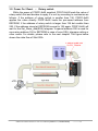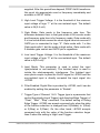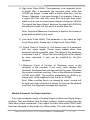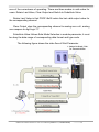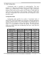
1
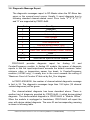
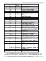
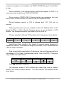
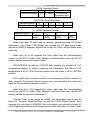
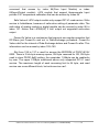
PROFI-8155/PROFI-8255
User Manual
PROFI-8155/8255 Remote I/O Unit User Manual (Version 1.0, October/2008)
-------------1
Warranty
All products manufactured by ICP DAS are warranted against
defective materials for a period of one year from the date of delivery
to the original purchaser.
Warning
ICP DAS assumes no liability for damages consequent to the
use of this product. ICP DAS reserves the right to change this
manual at any time without notice. The information furnished by ICP
DAS is believed to be accurate and reliable. However, no
responsibility is assumed by ICP DAS for its use, or for any
infringements of patents or other rights of third parties resulting from
its use.
Copyright
Copyright 2008 by ICP DAS Co., LTD. All rights reserved
worldwide.
Trademark
The names used for identification only may be registered
trademarks of their respective companies.
List of Revision
Date
2008/10
Author
Jeff Ma
Version
1.0
Revision
Release
PROFI-8155/8255 Remote I/O Unit User Manual (Version 1.0, October/2008)
-------------2
Table of Content
1.
2.
Introduction ..............................................................................................................................4
1.1.
Overview....................................................................................................................4
1.2.
Applications..............................................................................................................4
1.3.
Features .....................................................................................................................5
1.4.
Specifications...........................................................................................................6
1.5.
Modules Support .....................................................................................................7
Hardware ...................................................................................................................................8
2.1.
PROFI-8155/8255 Hardware Structure ...............................................................8
2.2.
Bus Wiring.................................................................................................................9
2.3.
PROFIBUS Cable and Transmission Distance ..............................................10
2.4.
2.5.
2.6.
3.
Status Indicator...................................................................................................... 11
Connector................................................................................................................13
Watchdog mechanism .........................................................................................14
2.7.
Node Address.........................................................................................................15
2.8.
Baud rate support .................................................................................................17
PROFIBUS DP System .........................................................................................................18
3.1.
The flow chart of the DP-slave ..........................................................................18
3.2.
Power On / Reset – Rotary switch ..............................................................19
3.3.
Parameterization Data..........................................................................................20
System parameters.......................................................................................................20
Module parameters for I-8K module.........................................................................20
Module Parameter for i-87K module: .......................................................................21
Module Parameter for Output modules: .................................................................24
3.4.
Wait Configuration ................................................................................................26
Configuration Data........................................................................................................26
3.5.
Data Exchange .......................................................................................................30
Numeric Representation .............................................................................................30
Byte Order and Data Address ....................................................................................43
3.6.
Diagnostic Message Report ...............................................................................53
3.7.
DP-V1 Acyclic Service..........................................................................................56
4.
5.
3.8.
Establish connection with PROFI-8X55 ..........................................................61
3.9.
Telegram cycle of data exchange .....................................................................62
PROFI-8X55 Guideline (Based on Step 7).......................................................................64
4.1.
Preprocessing........................................................................................................64
GSD File ...................................................................................................................................68
PROFI-8155/8255 Remote I/O Unit User Manual (Version 1.0, October/2008)
-------------3
1. Introduction
1.1. Overview
PROFIBUS is an open, digital communication system with a wide range of
applications, particularly in the fields of factory automation and process
automation. PROFIBUS is suitable for both fast, time-critical applications and
complex communication tasks. PROFIBUS-DP is a famous protocol that
enables simple, fast, cyclic and deterministic process data exchange between
Master and assigned Slave.
The PROFI-8155/8255 Remote I/O Unit is specially designed for the slave
device of PROFIBUS DP protocol. It supports up to 1/2 I/O slots for ICP DAS
i-8k series, i-87k Low Profile series and i-87k High Profiles series I/O modules.
In addition, we also provide the hot-swap function for i-87k High Profiles series
I/O modules. To setup PROFIBUS network, users can choose and configure
I/O modules by using the GSD file without any other setting tools.
1.2. Applications
• Industrial Automation
• Factory Automation
• Process Automation
• Etc…
PROFI-8155/8255 Remote I/O Unit User Manual (Version 1.0, October/2008)
-------------4
1.3. Features
Protocol & Hierarchy
Supports Transmission Rate
(Kbps)
Transmission Rate Setting
Address Setting
DP-V0 & DP-V1 Slave
9.6, 19.2, 45.45, 93.75, 187.5, 500,
1500, 3000, 6000, 12000
detected automatically
0~126 set by Rotary Switches
SSA-telegram set by DP-Master(Class 2)
Indicators
PWR, ERR, and RUN LEDs
I/O modules Configuration
Configured by GSD file
Supports I/O modules hot-swap
I-87K High Profile series
Network Isolation Protection
High Speed iCoupler
DC Isolation Protection
3000VDC on PROFIBUS side
4KV ESD Protection
Contact for each terminal
Number of Channel of Diag.
32
Device-Related Diag. Type
Offline Detection
PROFI-8155/8255 Remote I/O Unit User Manual (Version 1.0, October/2008)
-------------5
1.4. Specifications
Model
CPU
Flash
SRAM
EEPROM
Watch Dog Timer
Com1
PROFIBUS Interface
PROFIBUS Controller
PROFIBUS Transceiver
Transmission Rate
I/O Expansion Slot
Power Requirement
Power Supply
Power Consumption
Operating Temperature
Storage Temperature
Humidity
Dimensions
PROFI-8155
PROFI-8255
80186, 80MHz
512K Bytes
512K Bytes
2K Bytes
CPU Built-in
RS-232(F/W update port at JP1)
9-pin D-Sub(Female)
Siemens SPC3
ADI ADM2486 iCoupler Isolated
Transceiver
Up to 12Mbps
1 Slots
2 Slots
10V ~ 30V
8W
3W
-25℃ ~ +75℃
-30℃ ~ +85℃
5% ~ 95% No-Condensing
65x115x90 mm
95x115x90 mm
PROFI-8155/8255 Remote I/O Unit User Manual (Version 1.0, October/2008)
-------------6
1.5. Modules Support
Type
Module Name
Type
i-8040 / i-8051 / i-8052 /
i-8053 / i-8058
DI
i-87040 / i-87051 / i-87052 /
i-87053 / i-87058
i-87013 / i-87017 /
i-87018
AI
i-87040W / i-87046W /
i-87051W / i-87052W /
i-87053W / i-87053W-A5 /
i-87058W/ i-87059W
i-8037 / i-8041 / i-8056 /
i-8057 / i-8060 / i-8064 /
i-8065 / i-8066 / i-8068 /
i-8069
DO
i-87041 / i-87057 / i-87064 /
i-87065 / i-87066 / i-87068 /
i-87069
i-87054 / i-87055 / i-87063
i-87054W / i-87055W /
i-87063W
i-87013W / i-87015
/i-87015P/
i-87017W /
i-87017W-A5 /
i-87017R /
i-87017RC /
i-87018R / i-87018Z
/ i-87019R
i-8024
AO
i-87022 / i-87024 /
i-87026
i-87024W
i-87041W / i-87057W /
i-87064W / i-87065W /
i-87066W / i-87068W /
i-87069W
i-8042 / i-8050 / i-8054 /
i-8055 / i-8063 / i-8077
DI/O
Module Name
i-8017H / i-8017HS
i-8080
Counter /
Frequency
i-87082
i-87082W
PROFI-8155/8255 Remote I/O Unit User Manual (Version 1.0, October/2008)
-------------7
2. Hardware
2.1. PROFI-8155/8255 Hardware Structure
PROFI-8155/8255 Remote I/O Unit User Manual (Version 1.0, October/2008)
-------------8
2.2. Bus Wiring
In order to minimize the reflection effect of the signal transmission,
PROFIBUS device has to fit with an active terminal resistor at both first node
and last node, as shown below
However, the number of station in PROFIBUS network is also restricted.
According to PROFIBUS specification, it is up to 32 stations connected in a
PROFIBUS segment. If more than 32 stations are connected, the PROFIBUS
repeater must be used to link the individual bus segments.
PROFI-8155/8255 Remote I/O Unit User Manual (Version 1.0, October/2008)
-------------9
2.3. PROFIBUS Cable and Transmission Distance
The PROFIBUS cable with following properties has different transmission
distance with respect to different transmission rate, shown in the following
table
1.
2.
3.
4.
5.
Impedance :135~165Ω
Capacity : lower than 30 pF/m
Loop resistance : lower than 110Ω/Km
Wire diameter : larger than 0.65mm
Core cross-section : larger than 0.34mm2
Transmission Rate(Kbps)
9.6, 19.2, 45.45, 93.75
187.5
500
1500
3000, 6000, 12000
Transmission Distance per Segment (meter)
1200
1000
400
200
100
PROFI-8155/8255 Remote I/O Unit User Manual (Version 1.0, October/2008)
-------------10
2.4. Status Indicator
PROFI-8x55 provide three types of status indicators, they are PWR LED
(yellow), ERR LED (red) and RUN LED (green). When the power is supplied
to PROFI-8x55, PWR LED will turn on; Before PROFI-8x55 gets into the data
exchange state, ERR LED will turn on or flash; If CHK_CFG procedure is
finished, RUN LED will turn on and ERR LED will turn off. The table below
explains the relationship between linking status and recommend solutions.
Status Indicator
ERR ON &
RUN OFF
ERR Flash
(2Hz)
Meaning
PROFI-8x55 is offline
with no valid baud rate
(offline mode*)
PROFI-8x55 detects
baud rate, but is still
offline.(stop mode*)
PROFI-8x55 Prm is
Fault.(Note 1)
ERR Flash
(1Hz)
ERR ON & RUN
ON
ERR OFF & RUN
ON
PWR & ERR Flash
together(1Hz)
PWR & ERR Flash
Interlace(2Hz)
PROFI-8x55’s Cfg is
fault(Note 2)
PROFI-8x55 is in clear
mode*.
PROFI-8x55 is in
operation mode*.
PROFI-8x55 detect
module(s) offline
Diag Exist
(Diag. Msg. Request)
ERR Flash
(10Hz)
Recommend solution
Check the address setting of
PROFI-8x55 and DP-master.
Check the DP-Master is ready
to communicate with
PROFI-8x55.
Check the setting of
PROFI-8x55 in the master
interface and make sure of the
consistency.
Same as above
Sets the DP-Master from clear
mode to operation mode
Find the reason of the fault of
corresponding module.
Check the Input/Output value
that if exceed/under the limit
PROFI-8155/8255 Remote I/O Unit User Manual (Version 1.0, October/2008)
-------------11
Note 1: “Prm Fault” is the abbreviation of “Parameter Fault”; It means that the
number of parameter data which receive from DP-Master is not consistency
with DP-Slave (PROFI-8x55), and it could due to the difference between
module installation and master setting.
Note 2:“Cfg Fault” is the abbreviation of “Configuration Fault”, it means that
the number of configuration data which receive from DP-Master is not
consistency with DP-Slave (PROFI-8x55), and it could due to the wrong order
of installation.
Note *: there are four kinds of state in PROFIBUS DP Master.
1. Offline mode: Master not active on the bus.
2. Stop mode: Master only transmit token on the bus, and PROFIBUS
DP is not active.
3. Clear mode: DP Master active, but all output are zero or set to
fail-safe state.
4. Operate mode: DP Master full active.
Note: Diag. Exist mean that PROFI-8x55 detected the I/O value (analog signal)
of the module exceed or under the limitation of corresponding module, or
detected the line-broken of the temperature-sensor that should connect to the
module.
PROFI-8155/8255 Remote I/O Unit User Manual (Version 1.0, October/2008)
-------------12
2.5. Connector
The connector of PROFI-8x55 is shown below
Pin No. Signal
Meaning
3
B-Line
Receive/Transmit data - plus
4
CNTR-P Repeater control signal, RTS signal
5
GND
Power ground of bias terminator
6
VP
Power 5 volt of bias terminator
8
A-Line
Receive/Transmit data - minus
Note: The connector of PROFI-8x55 has no terminators; users must use the
cable connector that contain bias-terminator inside. The power of the
bias-terminator provide by PROFI-8x55 or other end-device.
PROFI-8155/8255 Remote I/O Unit User Manual (Version 1.0, October/2008)
-------------13
2.6. Watchdog mechanism
PROFI-8x55 has a built-in watchdog timer to monitor the linking status
with Master. In order to ensure an error-free connection, watchdog mechanism
divides into three stages.
In the first stage, watchdog detects the start delimiter whether valid or not
after the status of power supplied or system reset. If no SD1 telegram, SD2
telegram, or SD3 telegram are received completely, PROFI-8x55 will changes
the baud rate and continues detecting the correct baud rate. This stage is
called “Baud Search”.
If the watchdog has detected a valid SD telegram, it goes into the second
stage. In this stage, the watchdog monitors the integrity of the telegram. When
watchdog timer is expired and PROFI-8x55 doesn’t receive the complete
telegram, PROFI-8x55 will go to “Baud Search” state. This stage is called
“Baud Control”.
After PROFI-8x55 finished initializing, PROFI-8x55 waits for receiving the
Set_Prm telegram. If PROFI-8x55 receives the Set_Prm telegram with
“WD_On=1”, then watchdog goes into DP_Control and monitors the telegram
in Twd time. Otherwise, watchdog retains in the “Baud Control” state. This
stage is called “DP_Control”.
Besides the watchdog mechanism mentioned above, i-87K modules with
analog output or digital output have their own host watchdog to monitor the
status of PROFI-8x55. If PROFI-8x55 lost the control of DP-Master (due to
any unpredictable fault), it can’t send a specific watchdog command to flush
the watchdog timer of i-87K modules. Then the module will switch to safe
mode, and wait for resetting. There are three kinds of safe-value at safe-mode,
they are “retain last valid value”, “clear output”, and “switch to substitute value”.
Although i-8K support this safe-mechanism, but it has no ability to process the
fail safe value output by itself in case of MCU broken.
PROFI-8155/8255 Remote I/O Unit User Manual (Version 1.0, October/2008)
-------------14
2.7. Node Address
The figure shown above is the hexadecimal rotary switches. It dominates
the node (station) address of PROFI-8x55 in PROFIBUS. The switch which
labeled MSB is high nibble of address and the other one is low nibble of
address.
According to PROFIBUS specification, the station address which from 0 to
126 is valid, and the address 126 is a special address that supports remote
setting by SSA telegram from Class 2 DP-Master. PROFI-8x55 applies the
setting of rotary switch as its address if the address is valid. While the address
is invalid, PROFI-8x55 loads the pre-saved value from EEPROM. Moreover, if
the address is invalid (126) again, PROFI-8x55 awaits the SSA telegram and
applies it. (Note: If you want to clear the setting stored at EEPROM, you just
adjust rotary switch to FF before the power supplied).
Rotary
Switch(dec)
0~125
126~254
255
Pre-saved address
(EEPROM)
Don’t care
0~125
SSA Telegram
126
(default)
Accept with
address
0~125
impossible
Accept with
address
0~125
127~254
Clear to 126
No Accept
No Accept
PROFI-8x55
Station Address
Rotary Switch
Pre-saved address
(EEPROM)
SSA Telegram and
save address to
EEPROM
N/A
SSA Telegram and
save address to
EEPROM
PROFI-8155/8255 Remote I/O Unit User Manual (Version 1.0, October/2008)
-------------15
Note 1: Only one DP-Slave station with address 126 permitted in the bus.
Note 2: if you want to change the station address after data exchange,
PROFI-8455 should return to Wait-Prm state and wait for one second to apply
the new address.
PROFI-8155/8255 Remote I/O Unit User Manual (Version 1.0, October/2008)
-------------16
2.8. Baud rate support
PROFI-8x55 supports the entire baud rates of PROFIBUS. They are
9.6Kbps, 19.2Kbps, 45.45Kbps, 187.5Kbps, 500Kbps, 1.5Mbps, 3Mbps,
6Mbps, and 12Mbps. Because PROFI-8X55 has a functionality of auto-baud
rate detection, users needn’t to set the baud rate of PROFI-8x55.
Note: Many baud rates only are supported by the particular cable or speed.
For the details, please refer to the above section “PROFIBUS Cable and
Transmission Distance”
PROFI-8155/8255 Remote I/O Unit User Manual (Version 1.0, October/2008)
-------------17
3. PROFIBUS DP System
3.1. The flow chart of the DP-slave
Before DP-Slave switch to data exchange state, it employs some
telegrams to initialize and establish the connection with DP-Master. These
telegrams include Slave Diagnosis (Slave_Diag), Set Parameter (Set_Prm),
Check Configuration (Chk_Cfg), Slave Diagnosis, Data Exchange (Data_Exch)
and optional global control (GC). The explanation is as follows:
PROFI-8155/8255 Remote I/O Unit User Manual (Version 1.0, October/2008)
-------------18
3.2. Power On / Reset – Rotary switch
While the power of PROFI-8x55 supplied, PROFI-8x55 loads the value of
rotary switch first and decides to apply it or not by according to mechanism as
follows. If the address of rotary switch is smaller than 126, PROFI-8x55
applies the value directly. PROFI-8x55 loads the pre-saved address from
EEPROM, if the address of rotary switch is larger than 126 but smaller than
255. If the address stored at EEPROM is equal to 126 again, PROFI-8x55 will
wait for the Set_Slave_Add(SSA) telegram. A special address 255 is used for
recovering address 126 to EEPROM in case of error SSA_telegram setting or
other cases. For details, please refer to the next chapter. The figure below
shows the state flow of Wait SSA.
PROFI-8155/8255 Remote I/O Unit User Manual (Version 1.0, October/2008)
-------------19
3.3. Parameterization Data
In order to establish the connection completely, the DP-Slave should
obtain enough information from the DP-Master. The DP-Slave applies the
parameterization data to the I/O module of DP-Slave. DP-master divided
these parameters into two parts: one is master-related parameter, and another
one is module-related parameter. Master-related parameters provide the
common setting between DP-Master and DP-Slave (e.g. Byte-Order).
Module-related parameters provide the fundamental setting of the I/O modules
in DP-Slave. If the parameters have been applied successfully, DP-state will
switch to wait configuration, otherwise return to wait parameter.
PROFI-8x55 has two kinds of parameter data. First kind of parameters is
the system data, and another one is I/O module data. In i-8K modules, there is
no I/O module parameter except for i-8017H(S), i-8024, i-8050 and i-8080. In
i-87K modules, every module has their own parameters to determine the data
format and operation mode. We will describe the I/O modules individually in
next section.
System parameters
1. Byte-Order
The memory allocation is according to the slot identifier. Therefore, the
I/O module at slot 0 will allocate first, slot 1 in next and so on. Byte order is
an important factor related to the memory allocation. Big-endian byte order
(Motorola format) allocates more significant byte in lower memory address.
On the other hand, little-endian Byte order (Intel format) allocates more
significant byte in higher memory address.
For example, the integer which value is 0x0400(hex) will allocates
0x40(hex) in the first byte of the memory allocated to the integer and
0x00(hex) in the second byte.
Module parameters for I-8K module
i-8017H(S)
i-8017 is a standard analog input module; it requires the parameter of
“Data Format”, “Data Range” and “Diag Enable” to establish the
connection completely. In order to reduce the length of parameter data,
PROFI-8x55 encapsulates this information into one byte per channel. So
there are 8 bytes data for i-8017H and 16 bytes for i-8017HS.
Data range mean the measurement type (voltage, current) and range
PROFI-8155/8255 Remote I/O Unit User Manual (Version 1.0, October/2008)
-------------20
(-10v to 10v or 4mA to 20mA). Data format can be selected either engineer
unit format or hexadecimal format. “Diag Enable” is a flag that determines
PROFI-8455 whether diagnostic message will report or not.
i-8024:
i-8024 is similar to i-8017H(S) , please refer to i-8017H(S) .
i-8050:
i-8050 is a programmable digital input/output module with 16
programmable I/O. It is different from the other digital modules. Before
using i-8050, MCU must configure it first. PROFI-8x55 provides a 2-byte
parameter to configure i-8050. The first byte controls the direction (Input or
Output) of channel 15 to channel 8, and the second byte correspond to
channel 7 to channel 0. As mentioned above, digit ‘1’ represents input and
‘0’ represents output.
i-8080:
i-8080 is a counter/frequency module with 30 bytes parameter.
PROFI-8x55 divides these parameters into 2 parts; First part is only for
frequency mode, which are updated period of auto mode, low-frequency
mode, and high frequency respectively. Another part is for both Frequency
and Counter mode, which are XOR-Register, Channel Mode, Frequency
Band, Filter Enabled, and Low Pass Filter Pulse Width respectively. Note
that if frequency band selected inappropriately, it will induce to incorrect
measurement. For example, if an input signal is 80 KHz and frequency
band is set to low frequency band with 1000ms update period, then it will
measure 65.536 KHz instead of 80 KHz. Therefore selecting an
appropriate frequency band is necessary. For the detail, please refer to
i-8080 user manual. In additional, PROFI-8x55 provides another
parameter that chooses the trigger type of count clear. User can choose
one of them if needed.
Note: i-8080 hardware counter is 16 bit and maximum counter value is
65535. PROFI-8x55 uses the software method to expand this bound to 248,
so user should pay attention to some limitations.
Module Parameter for i-87K module:
Before using i-87K module with PROFI-8x55, it must be initialized the
PROFI-8155/8255 Remote I/O Unit User Manual (Version 1.0, October/2008)
-------------21
configuration. Unlike i-8K module, i-87K module uses the serial interface
to communicate with MCU. In the following section, we will introduce the
module parameters of i-87K briefly.
1. Type Code: Every operation mode has a unique type code in i-87K
module. Its range is from 0 to 128. This code dominates the
module’s behaviors which are voltage input, current input,
temperature input, digital I/O and so on. In general, most AI
modules support parts of type code. For example, i-87017 supports
type code 0x08 to 0x0D for voltage input.
2. Data Format: PROFI-8x55 provides four kinds of data format to
broaden the applicability. They are engineer unit format,
Hexadecimal format, percentage of full scale and Ohm in engineer
unit. Most i-87K modules support the first three formats, and the
last format is only supported by i-87013 and i-87015.
Besides the essential parameter mentioned above, a number of
modules have some additional parameter.
Analog Module, e.g. i-87013, i-87015, i-87017, i-87017R,
i-87017RC, i-87017ML, i-87018, i-87018R, i-87018Z, i-87019R,
i-87022, i-87024 and i-87026, have an additional parameter “Diag
Enable” to determine whether diagnosis report or not.
Among the analog modules, most of them share a common type
code. It means that every channel operates at the same mode, and
this manner will narrow its applicability. ICP DAS provides a number of
modules supporting individual channel configuration to solve this
problem; Analog Input modules i-87015, i-87018Z and i-87019R
provide individual channel configuration. In contrast to analog input
module, analog output modules i-87022 and i-87026 also support.
In Counter/Frequency module i-87082, type-code is fixed to 0x80,
and its parameters are divided into several parts, as shown below:
1. Frequency Gate Time: Frequency gate time is also called
“sampling period”. It controls the signal-passing time. The
counter takes effect during this period only, when AC-signal
PROFI-8155/8255 Remote I/O Unit User Manual (Version 1.0, October/2008)
-------------22
supplied. After this period has elapsed, PROFI-8x55 transforms
this count into appropriate count or frequency immediately and
available in INPUT buffer.
2. High Level Trigger Voltage: It is the threshold of the minimum
input voltage of logic “1” at the non-isolated input. The default
value is 24(2.4 volt).
3. Gate Mode: Gate mode is like frequency gate time. The
difference between them is that gate mode is for counter mode
and frequency gate time is for frequency mode. Gate mode with
0 is low active which means the count-signal take into account if
GATE pin is connected to logic “0”. Gate mode with 1 is like
Gate mode with 0, but the mode is high active. Gate mode with
2 disables gate control and GATE pin is regardless.
4. Low Level Trigger Voltage: It is the threshold of the maximum
input voltage of logic “0” at the non-isolated input. The default
value is 8(0.8 volt).
5. Input Mode: This parameter is used to select the input
type(isolated or non-isolated). The Isolated input is used to
isolate the electromagnetic interference. The Isolated input
uses photo-couple to pass the On/Off signal to i-87082 and the
non-isolated input is directly accepted the input signal into
i-87082.
6. Filter Enabled: Digital filter is provided by i-87082, and it can be
enabled by setting this parameter to “Enable”.
7. Trigger Type of Channel 1 & 0: Trigger type is a parameter that
control the polarity(Level Trigger) and direction(Edge Trigger) of
“Clear”, ”Start”, “Stop” command. The default setting is Rising
Edge Trigger. i-87082 can accept command only when the state
of the function selection is changed from 0(Disable) to 1(Start)
or 2(Stop) or 3(Clear). On the other hand, i-87082 accepts
command only with the value of the function selection larger
than 0 when the setting is High Level Trigger.
PROFI-8155/8255 Remote I/O Unit User Manual (Version 1.0, October/2008)
-------------23
8. High Level Pulse Width: This parameter is an important factor
of digital filter. It dominates the minimum pulse width that
i-87082 can accept. If pulse width is shorter than that, it will be
filtered. Otherwise, it can pass through. For example, if there is
a signal 200 KHz with duty cycle 50% and high level pulse
width is set to 3us, so measurement signal is limited to 166 KHz.
The signal has been filtered, because the signal with 200 KHz
has the pulse width of 2.5us and it is smaller than 3us.
Note: Formula of Maximum Frequency is equal to the inverse of
pulse width divided by duty cycle.
9. Low Level Pulse Width: This parameter is the same as High
Level Pulse width. Please refer to High Level Pulse Width.
10. Preset Count of Counter N: The preset count is a parameter
with four bytes length. Preset count loaded when clear
command issued or module reset. The range of this parameter
is between 0 and 232. Notice that this setting will not be cleared
by clear command. It only can be modified by Set_Prm
telegram.
11. Maximum Count of Counter N: Maximum count is the
threshold of the overflow. If the count value reaches this
threshold, the channel will overflow and halt for clear. Otherwise,
the counter continues counting. There is the difference between
i-87082 and i-8080. The overflow presentation in i-8080 is an
integer with 16 bits length just only one bit in i-87082.
Note: When overflow flag is not cleared by users, counter will
be held until clear command is issued. As soon as the channel
overflows, the diagnostic message will reported.
Module Parameter for Output modules:
The output modules consist of Analog Output modules and Digital Output
modules. They are different from the Input modules. Output modules have the
Safe Value output mechanism. They output the Safe Value while PROFI-8x55
has been changed to stop mode (or offline mode). The safe value can make
PROFI-8155/8255 Remote I/O Unit User Manual (Version 1.0, October/2008)
-------------24
sure of the correctness of operating. There are three modes in safe value for
users: Retain Last Value, Clear Output and Switch to Substitute Value.
Retain Last Value is that PROFI-8x55 retain the last valid output value for
the corresponding channel.
Clear Output clear the corresponding channel to analog zero volt, analog
zero ampere or digit logic “0”.
Substitute Value follows Safe Mode Selection in module parameter, it must
be obey the data range of corresponding data format and type-code.
The following figure shows the state flow of Wait Parameter.
PROFI-8155/8255 Remote I/O Unit User Manual (Version 1.0, October/2008)
-------------25
3.4. Wait Configuration
Configuration data is consisting of module-identifier. The main
purpose is to check the configuration data from DP-Master against the
stored one in PROFI-8x55. If these configuration data is coincident
between PROFI-8x55 and DP-master, the DP-mode of PROFI-8x55 will
switch from wait configuration to data exchange. Otherwise, PROFI-8x55
will report “Configuration Fault” and switch from wait configuration to wait
parameter again.
Configuration Data
Configuration data specifies the number of input/output bytes of
PROFI-8x55. PROFI-8x55 applies this information to allocate appropriate
number of memory space for the module plugged in I/O expansion slot on
PROFI-8x55. The maximum number of Input byte is 136 and 32 bytes for
output. It is not permitted to exceed this quantity. The following table
shows the module name and corresponding input byte, output byte and
configuration code.
Module name
i-8017HS – S1
i-8017H(S) – D2
i-8024
i-8037
i-8040
i-8041
i-8042
i-8050
i-8051
i-8052
i-8053
i-8054
i-8055
i-8056
i-8057
i-8058
i-8060
Input Length Output Length
16 Byte(8*2)
0
32 Byte(16*2)
0
0
8 Byte
0
2 Byte
4 Byte
0
0
4 Byte
2 Byte
2 Byte
2 Byte
2 Byte
2 Byte
0
1 Byte
0
2 Byte
0
1 Byte
1 Byte
1 Byte
1 Byte
0 Byte
2 Byte
0 Byte
2 Byte
1 Byte
0
0
1 Byte
PROFI-8155/8255 Remote I/O Unit User Manual (Version 1.0, October/2008)
Cfg Code
0x57
0x5F
0x63
0x21
0x13
0x23
0x31
0x31
0x11
0x10
0x11
0x30
0x30
0x21
0x21
0x10
0x20
-------------26
i-8063
1 Byte
1 Byte
0x30
i-8064
0
1 Byte
0x20
i-8065
0
1 Byte
0x20
i-8066
0
1 Byte
0x20
i-8068
0
1 Byte
0x20
i-8069
0
1 Byte
0x20
i-8077
1 Byte
1 Byte
0x20
i-8080
48Byte(8*6)
1 Byte
0xC0,0x00,0x2F
i-87013
8 Byte(4*2)
0
0x53
i-87015(P)
14 Byte(7*2)
0
0x56
i-87017(R)
16 Byte(8*2)
0
0x57
i-87017RC
16 Byte(8*2)
0
0x57
i-87017ML
16 Byte(8*2)
0
0x57
i-87018(R)
16 Byte(8*2)
0
0x57
@2
2 Byte(0+2 ) 0x57,0xC0,0x01,
i-87018(R)
18
@1
(w/ CJC Read/Offset) Byte(8*2+2 )
0x40
i-87018Z
20 Byte(10*2)
0
0x59
@2
3 Byte(0+3 ) 0x59,0xC0,0x02,
i-87018Z
22 Byte
@1
(w/ CJC Read/Offset) (10*2+2 )
0x40
i-87019R
16 Byte(8*2)
0
0x57
@2
3 Byte(0+3 ) 0x57,0xC0,0x02,
i-87019R
18
@1
(w/ CJC Read/Offset) Byte(8*2+2 )
0x40
i-87022
0
4 Byte(2*2)
0x61
i-87024
0
8 Byte(4*2)
0x63
i-87026
0
4 Byte(2*2)
0x61
i-87040(W)
4 Byte
0
0x13
i-87040(W)(w/ Cnt) 68 Byte(4+32*2) 5 Byte(0+4) 0x13,0xC0,0x03,
0x5F
i-87041(W)
0
4 Byte
0x23
i-87046W
2 Byte
0
0x11
i-87046W(w/ Cnt) 34 Byte(2+16*2) 2Byte(0+2) 0x11,0xC0,0x01,
0x4F
i-87051(W)
2 Byte
0
0x11
i-87051(W)(w/ Cnt) 34 Byte(2+16*2) 2 Byte(0+2) 0x11,0xC0,0x01,
0x4F
i-87052(W)
1 Byte
0
0x10
i-87052(W)(w/ Cnt) 17 Byte(1+8*2) 1 Byte(0+1) 0x10,0xC0,0x00,
0x47
PROFI-8155/8255 Remote I/O Unit User Manual (Version 1.0, October/2008)
-------------27
i-87053(W)
2 Byte
0
0x11
i-87053(W)(w/ Cnt) 34 Byte(2+16*2) 2 Byte(0+2) 0x11,0xC0,0x01,
0x4F
i-87054(W)
1 Byte
1 Byte
0x30
i-87054(W)(w/ Cnt) 17 Byte(1+8*2) 2 Byte(1+1) 0x30,0xC0,0x00,
0x47
i-87055(W)
1 Byte
1 Byte
0x30
i-87055(W)(w/ Cnt) 17 Byte(1+8*2) 2 Byte(1+1) 0x30,0xC0,0x00,
0x47
i-87057(W)
0
2 Byte
0x21
i-87058(W)
1 Byte
0
0x10
i-87058(W)(w/ Cnt) 17 Byte(1+8*2) 1 Byte(0+1) 0x10,0xC0,0x00,
0x47
i-87059W
1 Byte
0
0x10
i-87059W(w/ Cnt) 17 Byte(1+8*2) 1 Byte(0+1) 0x10,0xC0,0x00,
0x47
i-87063(W)
1 Byte
1 Byte
0x30
i-87063(w/ Cnt)
9 Byte(1+4*2) 2 Byte(1+1) 0x30,0xC0,0x00,
0x43
i-87064(W)
0
1 Byte
0x20
i-87065(W)
0
1 Byte
0x20
i-87066(W)
0
1 Byte
0x20
i-87068(W)
0
1 Byte
0x20
i-87069(W)
0
1 Byte
0x20
i-87082(W)
9 Byte
1 Byte(1 OR 1) 0x53,0x10,0x20
-S1 means single-end input mode
-D2 means differential input mode
- Data length of analog input module = channel number * data length per
channel.
-Data length of digital input module = the length of basic input data + channel
number * data length of counter per channel.
-Data length of digital output module = the length of basic output data +
optional data length of clear command.
-OR means DO data have combined with Clear command into one byte.
-@1 means the data length of CJC temperature.
-@2 means the data length of CJC offset setting command.
PROFI-8155/8255 Remote I/O Unit User Manual (Version 1.0, October/2008)
-------------28
The figure is shown below the state flow of Wait Configuration.
PROFI-8155/8255 Remote I/O Unit User Manual (Version 1.0, October/2008)
-------------29
3.5. Data Exchange
After the parameterization and configuration processes have been
accomplished, PROFI-8X55 exchanges I/O data with the DP-Master
cyclically. In following section, we introduce the Numeric Representation
and Byte Order briefly.
Numeric Representation
Among Analog Input modules or Analog Output modules, there are many
numeric representations, include Engineer-Unit, Hexadecimal, Percentage of
Full Scale and Ohm in Engineer-Unit. We will introduce the numeric
representation in i-8K module and i-87K module.
i-8K Series
Analog Input Module ( i-8017H, i-8017HS)
+/- 10 V :
The range for Engineer-Unit: -10000~10000(mV)
The range for 2’s complement hexadecimal: 0000~1FFF (0v ~ 10v),
2000~3FFF (-10v~1.22mV)
Conversion from Engineer-Unit to 2’s complement hexadecimal:
HexValue =
EngineerValue
× 8192 − 1
10000
HexValue =
EngineerValue
× 8192 + 16384
10000
Measurement Value
+10v(Engineer mode)
0v(Engineer mode)
-10v(Engineer mode)
+10v(Hex mode)
+5v(Hex mode)
0v(Hex mode)
-5v(Hex Mode)
-10v(Hex mode)
if 0 ≤ EngineerValue ≤ 10000
if -10000 ≤ EngineerValue < 0
Decimal
10000
0
-10000
8191
4095
0
12288
8192
Hexadecimal
0x2710
0x0000
0xD8F0
0x1FFF
0x1000
0x0000
0x3000
0x2000
PROFI-8155/8255 Remote I/O Unit User Manual (Version 1.0, October/2008)
-------------30
+/- 5 V :
The range for Engineer-Unit: -5000~5000(mV)
The range for 2’s complement hexadecimal: 0000~1FFF (0v ~ 5v),
2000~3FFF (-5v~0.61mV)
Conversion from Engineer-Unit to 2’s complement hexadecimal:
HexValue =
EngineerValue
× 8192 − 1
5000
HexValue =
EngineerValue
× 8192 + 16384
5000
Measurement Value
+5v(Engineer mode)
0v(Engineer mode)
-5v(Engineer mode)
+5v(Hex mode)
+2.5v(Hex mode)
0v(Hex mode)
-2.5v(Hex mode)
-5v(Hex Mode)
if 0 ≤ EngineerValue ≤ 5000
if -5000 ≤ EngineerValue < 0
Decimal
5000
0
-5000
8191
4095
0
12288
8192
Hexadecimal
0x1388
0x0000
0xEC78
0x1FFF
0x1000
0x0000
0x3000
0x2000
+/- 2.5 V :
The range for Engineer-Unit: -2500~2500(mV)
The range for 2’s complement hexadecimal: 0000~1FFF (0v ~ 2.5v),
2000~3FFF (-2.5v~0.3mV)
Conversion from Engineer-Unit to 2’s complement hexadecimal:
HexValue =
EngineerValue
× 8192 − 1
2500
HexValue =
EngineerValue
× 8192 + 16384
2500
Measurement Value
+2.5v(Engineer mode)
0v(Engineer mode)
-2.5v(Engineer mode)
+2.5v(Hex mode)
+1.25v(Hex mode)
0v(Hex mode)
-1.25v(Hex mode)
-2.5v(Hex Mode)
if 0 ≤ EngineerValue ≤ 2500
if -2500 ≤ EngineerValue < 0
Decimal
2500
0
-2500
8191
4095
0
12288
8192
Hexadecimal
0x09C4
0x0000
0xF63C
0x1FFF
0x1000
0x0000
0x3000
0x2000
PROFI-8155/8255 Remote I/O Unit User Manual (Version 1.0, October/2008)
-------------31
+/- 1.25 V :
The range for Engineer-Unit: -1250~1250(mV)
The range for 2’s complement hexadecimal: 0000~1FFF (0v ~ 1.25v),
2000~3FFF (-1.25v~0.15mV)
Conversion from Engineer-Unit to 2’s complement hexadecimal:
HexValue =
EngineerValue
× 8192 − 1
1250
HexValue =
EngineerValue
× 8192 + 16384
1250
Measurement Value
+1.25v(Engineer mode)
0v(Engineer mode)
-1.25v(Engineer mode)
+1.25v(Hex mode)
+0.675v(Hex mode)
0v(Hex mode)
-0.675v(Hex mode)
-1.25v(Hex Mode)
if 0 ≤ EngineerValue ≤ 1250
if -1250 ≤ EngineerValue<0
Decimal
1250
0
-1250
8191
4095
0
12288
8192
Hexadecimal
0x04E2
0x0000
0xFB1E
0x1FFF
0x1000
0x0000
0x3000
0x2000
+/- 20 mA :
The range for Engineer-Unit: -20000~20000(mV)
The range for 2’s complement hexadecimal: 0000~1FFF (0mA ~
20mA), 2000~3FFF (-20mA ~ -2.44uA)
Conversion from Engineer-Unit to 2’s complement hexadecimal:
HexValue =
EngineerValue
× 8192 − 1
20000
HexValue =
EngineerValue
× 8192 + 16384
20000
Measurement Value
20mA(Engineer mode)
10mA(Engineer mode)
0v(Engineer mode)
20mA(Hex mode)
10mA(Hex mode)
0v(Hex mode)
if 0 ≤ EngineerValue ≤ 20000
if -20000 ≤ EngineerValue<0
Decimal
20000
10000
0
8191
4095
0
Hexadecimal
0x4E20
0x2710
0x0000
0x1FFF
0x1000
0x0000
PROFI-8155/8255 Remote I/O Unit User Manual (Version 1.0, October/2008)
-------------32
Analog output module ( I-8024):
+/- 10 V :
The range for Engineer-Unit: -10000~10000(mV)
The range for 2’s complement hexadecimal: 0000~7FFF (0v ~ 10v),
8000~FFFF (-10v~0.3mV)
Conversion from Engineer-Unit to two’s complement hexadecimal:
HexValue =
EngineerValue
× 32768 − 1
10000
HexValue =
EngineerValue
× 32768 + 65536
10000
Measurement Value
10v(Engineer mode)
0v(Engineer mode)
-10v(Engineer mode)
10v(Hex mode)
0v(Hex mode)
-10v(Hex mode)
if 0 ≤ EngineerValue ≤ 10000
if -10000 ≤ EngineerValue<0
Decimal
10000
0
-10000
32767
0
-32768
Hexadecimal
0x2710
0x0000
0xD8F0
0x7FFF
0x1000
0x8000
+ 20mA :
The range for Engineer-Unit: -20000~20000(mV)
The range for 2’s complement hexadecimal: 0000~7FFF (0v ~ +20mA)
Conversion from Engineer-Unit to 2’s complement hexadecimal:
HexValue =
EngineerValue
× 32768 − 1
20000
Measurement Value
20mA(Engineer mode)
0mA(Engineer mode)
20mA(Hex mode)
0mA(Hex mode)
Decimal
20000
0
32767
0
Hexadecimal
0x4E20
0x0000
0x7FFF
0x0000
PROFI-8155/8255 Remote I/O Unit User Manual (Version 1.0, October/2008)
-------------33
i-87K Module
i-87K I/O modules are serial communication-based, they provide
various data formats. For example, Engineer-Unit, Percentage of Full
Scale, 2’s Complement Hexadecimal and Ohm format are supported in
these modules. The relationship between the measurement type and the
measurement unit is represented in the following table.
Type
Conditions
Voltage/Current -10V≦Voltage≦10V
20mA≧Current≧-20mA
Voltage≧10V or
Voltage
Voltage≦-10V
Temperature
RTD/Pt/Ni/Cu-RTD/Thermocouple
Resistor
RTD/Pt/Ni/Cu-RTD/Thermocouple
Unit
milli-Volt(mV)
micro-Ampere(µA)
Volt(V)
0.1 Degree Celsius
0.1 Ohm(0.1 Ω)
i-87013 and i-87015 Analog Input Module
Type-Code
Input Range
Data Format
Engineer Unit
Pt-100 (a =
% of FSR
20
0.00385) -100°C to
2's complement HEX
100°C
Ohm
Engineer Unit
Pt-100 (a =
% of FSR
21
0.00385) 0°C to
2's complement HEX
100°C
Ohm
Engineer Unit
Pt-100 (a =
% of FSR
22
0.00385) 0°C to
2's complement HEX
200°C
Ohm
Engineer Unit
Pt-100 (a =
% of FSR
23
0.00385) 0°C to
2's complement HEX
600°C
Ohm
Engineer Unit
Pt-100 (a =
% of FSR
24
0.003916) -100°C to
2's complement HEX
100°C
Ohm
Max.
+1000
+10000
7FFF
+1385
+1000
+10000
7FFF
+1385
+2000
+10000
7FFF
+1758
+6000
+10000
7FFF
+3135
+1000
+10000
7FFF
+1391
PROFI-8155/8255 Remote I/O Unit User Manual (Version 1.0, October/2008)
Min
-1000
-10000
8000
+0602
+0000
+00000
0000
+1000
+0000
+00000
0000
+1000
+0000
+00000
0000
+1000
-1000
-10000
8000
+0595
-------------34
25
Pt-100 (a =
0.003916) 0°C to
100°C
26
Pt-100 (a =
0.003916) 0°C to
200°C
27
Pt-100 (a =
0.003916) 0°C to
600°C
28
Nickel 120
-80°C to 100 °C
29
Nickel 120
0°C to 100°C
2A
Pt-1000(a =
0.00385) -200°C to
600°C
2B
Cu 100 (a =
0.00421) -20°C to
150°C
2C*1
Cu 100 a = 0.00421
0°C to 200°C
*1
*1
2D
2E*2
Cu 1000 a =
0.00421
-20°C to 150°C
Pt 100 a = 0.00385
-200°C to +200°C
Engineer Unit
% of FSR
2's complement HEX
Ohm
Engineer Unit
% of FSR
2's complement HEX
Ohm
Engineer Unit
% of FSR
2's complement HEX
Ohm
Engineer Unit
% of FSR
2's complement HEX
Ohm
Engineer Unit
% of FSR
2's complement HEX
Ohm
Engineer Unit
% of FSR
2's complement HEX
Ohm
Engineer Unit
% of FSR
2's complement HEX
Ohm
Engineer Unit
% of FSR
2's complement HEX
Ohm
Engineer Unit
% of FSR
2's complement HEX
Ohm
Engineer Unit
% of FSR
+1000
+10000
7FFF
+1391
+2000
+10000
7FFF
+1771
+6000
+10000
7FFF
+3172
+1000
+10000
7FFF
+2006
+1000
+10000
7FFF
+2006
+6000
+10000
7FFF
+31371
+1500
+10000
7FFF
+1631
+2000
+10000
7FFF
+1677
+1500
+10000
7FFF
+16317
+2000
+10000
PROFI-8155/8255 Remote I/O Unit User Manual (Version 1.0, October/2008)
+0000
+00000
0000
+1000
+0000
+00000
0000
+1000
+0000
+00000
0000
+1000
-0800
-08000
999A
+1206
+0000
+00000
0000
+1206
-2000
-03333
D556
+01852
-0200
-01333
EEEF
+0915
0000
-00000
0000
+0903
-0200
-01333
EEEF
+09156
-2000
-10000
-------------35
2's complement HEX 7FFF
8000
Ohm
+1758 +0184
Engineer Unit
+2000 -2000
Pt 100 a = 0.003916
% of FSR
+10000 -10000
2F*2
-200°C to +200°C 2's complement HEX 7FFF
8000
Ohm
+1771 +0171
Engineer Unit
+6000 -2000
Pt 100 a = 0.00385
% of FSR
+10000 -03333
80*2
-200°C to +600°C 2's complement HEX 7FFF
D556
Ohm
+3135 +0184
Engineer Unit
+6000 -2000
Pt 100 a = 0.003916
% of FSR
+10000 -03333
81*2
-200°C to +600°C 2's complement HEX 7FFF
D556
Ohm
+3172 +0171
* 1: Type 2B, 2C and 2D are only available with i-87015.
* 2: Type 2E, 2F, 80 and 81 are only available with the i-87015 firmware
version A1.10 and later, i-87013 firmware version B1.3 and later.
i-87017/i-87017R Analog Input Module
Type-Code
Input Range
Data Format
Engineer Unit
08
-10V to +10V
% of FSR
2's Complement HEX
Engineer Unit
09
-5V to +5V
% of FSR
2's Complement HEX
Engineer Unit
0A
-1V to +1V
% of FSR
2's Complement HEX
Engineer Unit
0B
-500mV to +500mV
% of FSR
2's Complement HEX
Engineer Unit
0C
-150mV to +150mV
% of FSR
2's Complement HEX
0D
-20mA to +20mA
Engineer Unit
Max.
+10000
+10000
7FFF
+50000
+10000
7FFF
+10000
+10000
7FFF
+500
+10000
7FFF
+150
+10000
7FFF
+20000
PROFI-8155/8255 Remote I/O Unit User Manual (Version 1.0, October/2008)
Min
-10000
-10000
8000
-50000
-10000
8000
-10000
-10000
8000
-500
-10000
8000
-150
-10000
8000
-20000
-------------36
% of FSR
+10000 -10000
2's Complement HEX 7FFF
8000
i-87017RC Analog Input Module
Type-Code
Input Range
07
0D
1A
Data Format
Engineer Unit
-4mA to +20mA
% of FSR
2's Complement HEX
Engineer Unit
-20mA to +20mA
% of FSR
2's Complement HEX
Engineer Unit
+0A to +20mA
% of FSR
2's Complement HEX
Max.
+04000
+10000
7FFF
+20000
+10000
7FFF
+00000
+10000
7FFF
Min
+20000
-10000
8000
-20000
-10000
8000
+20000
-10000
8000
i-87017ML Analog Input Module
Type-Code
Input Range
1B
1C
Data Format
Max.
Min
Engineer Unit
+150
-150
-150V to +150V
% of FSR
+10000 -10000
2's Complement HEX 7FFF
8000
Engineer Unit
+50
-50
-50V to +50V
% of FSR
+10000 -10000
2's Complement HEX 7FFF
8000
i-87018/i-87018R Analog Input Module
Type-Code
Input Range
Data Format
Max.
Min
Engineer Unit
+15
-15
00
-15mV to +15mV
% of FSR
+10000 -10000
2's Complement HEX 7FFF
8000
Engineer Unit
+50
-50
01
-50mV to +50mV
% of FSR
+10000 -10000
2's Complement HEX 7FFF
8000
Engineer Unit
+100
-100
02
-100mV to +100mV
% of FSR
+10000 -10000
2's Complement HEX 7FFF
8000
03
-500mV to +500mV
Engineer Unit
+500
-500
PROFI-8155/8255 Remote I/O Unit User Manual (Version 1.0, October/2008)
-------------37
04
-1V to +1V
05
-25V to +25V
06
-20mA to +20mA
0E
J Type
0F
K Type
10
T Type
11
E Type
12
R Type
13
S Type
14
B Type
15
N Type
% of FSR
2's Complement HEX
Engineer Unit
% of FSR
2's Complement HEX
Engineer Unit
% of FSR
2's Complement HEX
Engineer Unit
% of FSR
2's Complement HEX
Engineer Unit
% of FSR
2's Complement HEX
Engineer Unit
% of FSR
2's Complement HEX
Engineer Unit
% of FSR
2's Complement HEX
Engineer Unit
% of FSR
2's Complement HEX
Engineer Unit
% of FSR
2's Complement HEX
Engineer Unit
% of FSR
2's Complement HEX
Engineer Unit
% of FSR
2's Complement HEX
Engineer Unit
% of FSR
2's Complement HEX
+10000
7FFF
+10000
+10000
7FFF
+25000
+10000
7FFF
+20000
+10000
7FFF
+7600
+10000
7FFF
+13720
+10000
7FFF
+4000
+10000
7FFF
+10000
+10000
7FFF
+17680
+10000
7FFF
+17680
+10000
7FFF
+18200
+10000
7FFF
+13000
+10000
7FFF
PROFI-8155/8255 Remote I/O Unit User Manual (Version 1.0, October/2008)
-10000
8000
-10000
-10000
8000
-25000
-10000
8000
-20000
-10000
8000
-2100
-02763
DCA2
-02700
-01968
E6D0
-2700
-06750
A99A
-02700
-02700
DD71
+00000
+00000
0000
+00000
+00000
0000
+00000
+00000
0000
-02700
-02077
E56B
-------------38
16
C Type
17
L Type
18
M Type
19
L Type
DIN43710
i-87019R Analog Input Module
Type-Code
Input Range
00
-15mV to +15mV
01
-50mV to +50mV
02
-100mV to +100mV
03
-500mV to +500mV
04
-1V to +1V
05
-2.5V to +2.5V
06
-20mA to +20mA
Engineer Unit
% of FSR
2's Complement HEX
Engineer Unit
% of FSR
2's Complement HEX
Engineer Unit
% of FSR
2's Complement HEX
Engineer Unit
% of FSR
2's Complement HEX
+23200
+10000
7FFF
+8000
+10000
7FFF
+1000
+05000
4000
+9000
+10000
7FFF
+00000
+00000
0000
-2000
-02500
E000
-2000
-10000
8000
-2000
-02222
E38F
Data Format
Engineer Unit
% of FSR
2's Complement HEX
Engineer Unit
% of FSR
2's Complement HEX
Engineer Unit
% of FSR
2's Complement HEX
Engineer Unit
% of FSR
2's Complement HEX
Engineer Unit
% of FSR
2's Complement HEX
Engineer Unit
% of FSR
2's Complement HEX
Engineer Unit
% of FSR
Max.
+15
+10000
7FFF
+50
+10000
7FFF
+100
+10000
7FFF
+500
+10000
7FFF
+10000
+10000
7FFF
+25000
+10000
7FFF
+20000
+10000
Min
-15
-10000
8000
-50
-10000
8000
-100
-10000
8000
-500
-10000
8000
-10000
-10000
8000
-25000
-10000
8000
-20000
-10000
PROFI-8155/8255 Remote I/O Unit User Manual (Version 1.0, October/2008)
-------------39
08
09
0A
0B
0C
0D
0E
0F
10
11
12
13
2's Complement HEX
Engineer Unit
-10V to +10V
% of FSR
2's Complement HEX
Engineer Unit
-5V to +5V
% of FSR
2's Complement HEX
Engineer Unit
-1V to +1V
% of FSR
2's Complement HEX
Engineer Unit
-500mV to +500mV
% of FSR
2's Complement HEX
Engineer Unit
-150mV to +150mV
% of FSR
2's Complement HEX
Engineer Unit
-20mA to +20mA
% of FSR
2's Complement HEX
Engineer Unit
J Type
% of FSR
2's Complement HEX
Engineer Unit
K Type
% of FSR
2's Complement HEX
Engineer Unit
T Type
% of FSR
2's Complement HEX
Engineer Unit
E Type
% of FSR
2's Complement HEX
Engineer Unit
R Type
% of FSR
2's Complement HEX
S Type
Engineer Unit
7FFF
+10000
+10000
7FFF
+50000
+10000
7FFF
+10000
+10000
7FFF
+500
+10000
7FFF
+150
+10000
7FFF
+20000
+10000
7FFF
+7600
+10000
7FFF
+13720
+10000
7FFF
+4000
+10000
7FFF
+10000
+10000
7FFF
+17680
+10000
7FFF
+17680
PROFI-8155/8255 Remote I/O Unit User Manual (Version 1.0, October/2008)
8000
-10000
-10000
8000
-50000
-10000
8000
-10000
-10000
8000
-500
-10000
8000
-150
-10000
8000
-20000
-10000
8000
-2100
-02763
DCA2
-02700
-01968
E6D0
-2700
-06750
A99A
-02700
-02700
DD71
+00000
+00000
0000
+00000
-------------40
14
B Type
15
N Type
16
C Type
17
L Type
18
M Type
19
L Type
DIN43710
% of FSR
2's Complement HEX
Engineer Unit
% of FSR
2's Complement HEX
Engineer Unit
% of FSR
2's Complement HEX
Engineer Unit
% of FSR
2's Complement HEX
Engineer Unit
% of FSR
2's Complement HEX
Engineer Unit
% of FSR
2's Complement HEX
Engineer Unit
% of FSR
2's Complement HEX
+10000
7FFF
+18200
+10000
7FFF
+13000
+10000
7FFF
+23200
+10000
7FFF
+8000
+10000
7FFF
+1000
+05000
4000
+9000
+10000
7FFF
+00000
0000
+00000
+00000
0000
-02700
-02077
E56B
+00000
+00000
0000
-2000
-02500
E000
-2000
-10000
8000
-2000
-02222
E38F
i-87022 Analog Output Module
Type-Code Input Range
0
1
2
Data Format
Max.
Min
Engineer Unit 20000 00000
0mA to 20mA
% of FSR
+10000 +00000
Hexadecimal
FFF
000
Engineer Unit 20000 04000
4 mA to 20mA
% of FSR
+10000 +00000
Hexadecimal
FFF
000
Engineer Unit 10000 00000
0V to 10V
% of FSR
+10000 +00000
Hexadecimal
FFF
000
PROFI-8155/8255 Remote I/O Unit User Manual (Version 1.0, October/2008)
-------------41
i-87026 Analog Output Module
Type-Code Input Range
0
1
2
Data Format
Max.
Min
Engineer Unit 20000 00000
0 mA to 20mA
% of FSR
+10000 +00000
Hexadecimal FFFF
0000
Engineer Unit 20000 04000
4 mA to 20mA
% of FSR
+10000 +00000
Hexadecimal FFFF
0000
Engineer Unit 10000 00000
0V to 10V
% of FSR
+10000 +00000
Hexadecimal FFFF
0000
i-87024 Analog Output(Only support Engineer Unit)
Type-Code Input Range Data Format
Max.
30
0 mA to 20mA Engineer Unit +20000
31
4 mA to 20mA Engineer Unit +20000
32
0V to 10V
Engineer Unit +10000
33
-10V to 10V Engineer Unit +10000
34
0V to 5V
Engineer Unit +05000
35
-5V to 5V
Engineer Unit +05000
PROFI-8155/8255 Remote I/O Unit User Manual (Version 1.0, October/2008)
Min
+00000
+04000
+00000
-10000
+00000
-05000
-------------42
Byte Order and Data Address
i-8K Series & i-87K Series - General Digital Input / Output
The general digital input or output module arrange its data with big-endian
in follow (i-8040 or i-87040).
The little-endian is shown as follows.
i-87K Series - Digital Input w/ Counter
The i-87K digital input modules not only provide a basic input function but
also have a function of counter which maximum count can be up to 65535.
You can choose it which label “i-870XX w/ Counter Func.” in GSD file. The
figure shows below is data arrangement of i-87040 w/ Counter.
Data Arrangement of Digital Input w/ Counter: Input Part
Data Arrangement of Digital Input w/ Counter: Output Part
PROFI-8155/8255 Remote I/O Unit User Manual (Version 1.0, October/2008)
-------------43
i-8K Series & i-87K Series – General Analog Input ( w/o CJC
Read/Offset ) and Analog Output
Analog module transforms the continuous signal or discrete signal into
another type signal. Discrete signal always 2 byte per channel. For example,
the following figure shows data arrangement of i-87024(i-8024).
Note: The order of I/O data is ranked by channel’s identifier, so the channel
with lower ID has priority over the channel with higher ID.
i-8K Series & i-87K Series – General Analog Input (w/ CJC
Read/Offset )
The temperature is a kind of analog signals. i-87K modules(i-87013,
i-87015, i-87018 and i-87019) provide several solutions to measure the
different sensors or range. Most of temperature sensor return the absolution
value, but the thermocouple is different, it return the relative-value between
hot-junction and cold junction. The thermocouples measure the temperature
difference between hot junction point and cold junction point. But the ordinary
thermocouples have no cold-junction point so it can not measure the accuracy
PROFI-8155/8255 Remote I/O Unit User Manual (Version 1.0, October/2008)
-------------44
temperature using hot junction point only. In order to solve this problem, i-87K
modules which use thermocouple to measure temperature support the Cold
Junction Compensation by an internal temperature sensor. Although CJC’s
problem has been dealt, there is a problem still remained. The problem is that
CJC temperature sensor has some varieties compare to practical temperature.
Therefore, PROFI-8x55 provides a byte to calibration this difference. The
following figure is data arrangement of i-87024 w/ CJC Read/Offset.
The bytes of CJC offset detail describes as follows. There are two kinds of
data length, 2 bytes and 3 bytes. The data length with 2 byte is used in module
without individual channel configure and the data length with 3 byte is used in
module with individual channel configure.
PROFI-8155/8255 Remote I/O Unit User Manual (Version 1.0, October/2008)
-------------45
Bit.
Func.
Bit Arrangement of CJC-Offset using Big-Endian
Byte0.3~0 Byte1.7
Byte1.6 Byte1.5
Byte 1.4~Byte2.0
Chn.Sel. Ena/Disa Reserved
Sign
Offset-Value(0.01℃)
Bit.
Func.
Bit Arrangement of CJC-Offset using Little-Endian
Byte2.3~0 Byte1.7
Byte1.6 Byte1.5
Byte 1.4~Byte0.0
Chn.Sel. Ena/Disa Reserved
Sign
Offset-Value
Func.
Chn.Sel.(8bits) *
Ena/Disa(1bit)
Reserved(1bit)
Sign(1bit)
Meaning
Channel Selection(0~8)
Enable/Disable
Reserved
Sign (0 -> Pos, 1-> Neg)
Description
CJC Calibration Channel
CJC Calibration Enable
Plus or minus offset value to
calibration temperature
Offset-Value
Offset value
Offset value compare to
(13bit)
practice temperature
*: This field only available in i-87019R. “Chn.Sel.” from 0 to 7 is corresponding
to channel 0 to channel 7 and Chn.Sel. 8 is a broadcast channel ID that
available to all channel.
Note: The maximum offset for i-87019R is 4096 and its unit is 0.01℃; The
maximum offset for i-87108Z is 127 and its unit is 0.1℃
Note: While Enable/Disable is set (“1”), the calibration works.
Note: The length of output data in i-87018(R/W) is 2 bytes, and 3 bytes for
i-87019R and i-87018Z.
i-8K Series & i-87K Series – Counter/Frequency
i-8080 and i-87082 are counter/frequency module, the differences
described in the following table.
Module Name
Count Range
Frequency Range
Overflow
Channel Number
i-8080
0~248(Count+Overflow)
0~450KHz
0~216
8(Up & Freq) or 4(others)
i-87082
0~232(Count)
0~100KHz
0~1
2
The following figure shows the data arrangement of input data. It includes
the normal count (4 Bytes) and overflow count (2bytes).
PROFI-8155/8255 Remote I/O Unit User Manual (Version 1.0, October/2008)
-------------46
Data arrangement of input part in i-8080 module
There are nine input bytes in i-87082. The last byte indicates the status of
the counter, and the others are the count value of each channel. The bit
arrangement of the last input byte is shown below
i-87082 – bit arrangement of the last input byte (Overflow)
Bit.
Bit7 Bit6 Bit5 Bit4 Bit3 Bit2
Bit1
Bit0
Func.
Reserved
CH1.Overflow CH0.Overflow
The following figure shows the data arrangement of the input bytes in
i-87082 module.
PROFI-8155/8255 Remote I/O Unit User Manual (Version 1.0, October/2008)
-------------47
i-87082 - Data arrangement of the input bytes (Cnt/Freq)
There is an additional function in both of i-8080 and i-87082. It is “Clear
Count” command. The clear command of i-8080 is the same as i-87082. It just
set the corresponding bit to “1”(Level-trigger) or set it from “0” to “1”
(Edge-trigger) then the corresponding channel count will clear soon, as show
below.
Bit Arrangement of Output Data in i-8080(1 Byte)
Bit.
7
6
5
4
3
2
1
0
Func.
Clr7 Clr6 Clr5 Clr4 Clr3 Clr2 Clr1 Clr0
Func.
ClrN
Meaning
Clear Count of Channel N
Description
Clear both overflow and count value
i-87082 provide more functionality than i-8080. They are “Start Count”
and ”Stop Count”. These functionalities increase the applicability of i-87082
module. For more detail description, please refer to the following table.
i-87082 output data (1 Byte)
Bit
7
6
5
4
3
2
1
0
Func. E-DO.1 E-DO.0 DO.1 DO.0 C1.S1 C1.S0 C0.S1 C0.S0
PROFI-8155/8255 Remote I/O Unit User Manual (Version 1.0, October/2008)
-------------48
Func.
Meaning
E-DO.1 Enable DO.1
E-DO.0 Enable DO.0
DO.1
DO.0
C1.S1
C1.S0
C0.S1
C0.S0
Digital Output CH1
Digital Output CH0
Channel 1 Func.Sel. 1
Channel 1 Func.Sel. 0
Channel 0 Func.Sel. 1
Channel 0 Func.Sel. 0
Func.S1
0
0
1
1
Func.S0
0
1
0
1
Descriptions
Enable=1, DO.1 is output.
Enable=0, No output.
Enable=1, DO.0 is output.
Enable=0, No output.
Digital Output value of Channel 1.
Digital Output value of Channel 0.
Channel 1 Function Selection.
See table below.
Channel 0 Function Selection.
See table below.
Function
No Action(Disable)
Stop counting
Start counting
Clear count
Statistic Table of i-8K & i-87K
The following table shows the memory allocation of standard I/O and
Counter / Frequency module, and we divide this table into four parts: The first
table describes each function’s meaning. The second table shows the input
allocation of standard I/O, the third table shows the output allocation of
standard I/O and the last part shows the Input/Output memory allocation of the
Counter/Frequency module. We have simplified the following tables. The
remainders of the table must be deduced by users.
Function Description Table
Function Name
Meaning
Da~b
Digital I/O Value(bit a~b)
A.Na~b
Analog Value of Channel N(bit a~b)
C.Na~b
Count Value of Channel N(bit a~b)
CJCa~b
CJC Temperature(bit a~b)
Clra~b
Clear Command(bit a~b)
OvNa~b
Overflow Indicator(bit a~b)
PROFI-8155/8255 Remote I/O Unit User Manual (Version 1.0, October/2008)
-------------49
Standard I/O – input memory allocation
Meas.Type
DI
DI w/ Count
AI
Byte.Order Big
Little
Big
Little
Big
Little
BYTE.0
D24~31 D0~7 D24~31 D0~7
A.08~15 A.00~7
BYTE.1
D16~23 D8~15 D16~23 D8~15
A.00~7 A.08~15
BYTE.2
D8~15 D16~23 D8~15
D16~23 A.18~15 A.10~7
BYTE.3
D0~7 D24~31 D0~7
D24~31 A.10~7 A.18~15
BYTE.4
C.08~15 C.00~7 A.28~15 A.20~7
BYTE.5
C.00~7 C.08~15 A.20~7 A.28~15
BYTE.6
C.18~15 C.10~7 A.38~15 A.30~7
BYTE.7
C.10~7 C.18~15 A.30~7 A.38~15
BYTE.8
C.28~15 C.20~7 A.48~15 A.40~7
BYTE.9
C.20~7 C.28~15 A.40~7 A.48~15
BYTE.10
C.38~15 C.30~7 A.58~15 A.50~7
BYTE.11
C.30~7 C.38~15 A.50~7 A.58~15
BYTE.12
C.48~15 C.40~7 A.68~15 A.60~7
BYTE.13
C.40~7 C.48~15 A.60~7 A.68~15
BYTE.14
C.58~15 C.50~7 A.78~15 A.70~7
BYTE.15
C.50~7 C.58~15 A.70~7 A.78~15
BYTE.16
C.68~15 C.60~7
BYTE.17
C.60~7 C.68~15
AI w/ CJC.read
Big
Little
A.08~15 A.00~7
A.00~7
A.08~15
A.18~15 A.10~7
A.10~7
A.18~15
A.28~15 A.20~7
A.20~7
A.28~15
A.38~15 A.30~7
A.30~7
A.38~15
A.48~15 A.40~7
A.40~7
A.48~15
A.58~15 A.50~7
A.50~7
A.58~15
A.68~15 A.60~7
A.60~7
A.68~15
A.78~15 A.70~7
A.70~7
A.78~15
CJC8~15 CJC0~7
CJC0~7 CJC8~15
Standard I/O – output memory allocation
Meas.Type
DO
DI w/ Count
AO
AI w/ CJC.offset
Byte.Order Big
Little
Big
Little
Big
Little
Big
Little
BYTE.0
D24~31 D0~7 clr24~31 clr0~7 A.08~15 A.00~7 ChnSel offset7~0
Ena&
BYTE.1
D16~23 D8~15 clr16~23 clr8~15 A.00~7 A.08~15 Ena&
offset8~15 offset8~15
BYTE.2
BYTE.3
BYTE.4
BYTE.5
BYTE.6
BYTE.7
BYTE.8
BYTE.9
BYTE.10
BYTE.11
D8~15
D0~7
D16~23 clr8~15
D24~31 clr0~7
clr16~23 A.18~15
clr24~31 A.10~7
A.28~15
A.20~7
A.38~15
A.30~7
A.48~15
A.40~7
A.58~15
A.50~7
A.10~7 offset7~0
A.18~15
A.20~7
A.28~15
A.30~7
A.38~15
A.40~7
A.48~15
A.50~7
A.58~15
PROFI-8155/8255 Remote I/O Unit User Manual (Version 1.0, October/2008)
ChnSel
-------------50
Counter/Frequency memory allocation
Meas.Type i-8080.Inp.
i-8080.Outp. i-87082.Inp
Byte.Order Big
Little
Big
Little Big
Little
BYTE.0
C024~31 C00~7
Clr0~7 Clr0~7 C024~31 C00~7
BYTE.1
BYTE.2
BYTE.3
BYTE.4
BYTE.5
BYTE.6
BYTE.7
BYTE.8
BYTE.9
BYTE.10
BYTE.11
BYTE.12
BYTE.13
BYTE.14
BYTE.15
BYTE.16
BYTE.17
C016~23
C08~15
C00~7
Ov08~15
Ov00~7
C124~31
C116~23
C18~15
C10~7
Ov18~15
Ov10~7
C224~31
C216~23
C28~15
C20~7
Ov28~15
Ov20~7
C08~15
C016~23
C024~31
Ov00~7
Ov08~15
C10~7
C18~15
C116~23
C124~31
Ov10~7
Ov18~15
C20~7
C28~15
C216~23
C224~31
Ov20~7
Ov28~15
C016~23
C08~15
C00~7
C124~31
C116~23
C18~15
C10~7
Ov00~1
i-87082.Outp
Big
Little
E-DO.1
/E-DO.2
/DO.1
/DO.0
/C1.S1
/C1.S0
/C0.S1
/C0.S0
E-DO.1
/E-DO.2
/DO.1
/DO.0
/C1.S1
/C1.S0
/C0.S1
/C0.S0
C08~15
C016~23
C024~31
C10~7
C18~15
C116~23
C124~31
Ov00~1
The following figures describe the state flow of data exchange. The first
figure shows the state flow of data exchange. There are four modules
(i-87018Z, i-87024, i-87017W and i-87082) plugged in PROFI-8x55.
PROFI-8155/8255 Remote I/O Unit User Manual (Version 1.0, October/2008)
-------------51
The second figure shows another state flow of data exchange. There is no
output module that installation in PROFI-8x55 and only input module install.
PROFI-8155/8255 Remote I/O Unit User Manual (Version 1.0, October/2008)
-------------52
3.6. Diagnostic Message Report
The diagnostic messages report to DP-Master when the DP-Slave has
errors or the unusual event occurs. Usually, It report diagnosis due to
following standard channel-related event. Error code “2”,”3”,”5”,”6”,”7”
and ”8” are supported by PROFI-8x55.
Error Code
Error Type
0
Reserved
1
Short Circuit
2
Under-voltage
3
Over-voltage
4
overload
5
Over-temperature
6
Line/wire Break(Sensor Only)
7
Upper Limit Value Exceeded(Current)
8
Lower Limit Value Exceeded(Current, Sensor)
9
Error
10~15
Reserved
16~31
Manufacture Specific/Device-Related
PROFI-8x55 provides diagnosis report for Analog I/O and
Counter/Frequency module. In Analog I/O module, the reason of diagnosis
reports is that the input/output/count exceeds the default maximum value/
minimum value or temperature sensor line break. In Counter/Frequency
modules (I-87082 only), it usually due to the count exceeds the setting of
“Maximum Count of Counter N” that set by Set_Prm telegram.
In PROFI-8155/8255, the number of channel-related diagnostic message
is limit to 32. The diagnostic messages large than 104 bytes (39 channel
-related diagnoses) will be ignore.
The channel-related diagnosis has been described above. There is
another kind of diagnosis provided by PROFI-8x55; it called device-related
diagnosis. The device-related diagnosis in PROFI-8x55 is “Module Offline”.
When the module is unplugged or breakdown, PROFI-8x55 will report the
error with device-related diagnosis. The error-ID and corresponding meaning
is shown in following table.
PROFI-8155/8255 Remote I/O Unit User Manual (Version 1.0, October/2008)
-------------53
Error ID
1
2
Meaning
Slot 0- Module Offline
Slot 1- Module Offline
Several offline modules can be detected at the same time.
PROFI-8155/8255 combines these Error-IDs into one byte and return to
DP-Master once. For example, we know that all the modules in PROFI-8x55
disconnect (offline) when DP-Master gets a device-related diagnosis with error
code “3”. There are two examples that describe different error or warning
event as follows. The first example is about that the I-87082 module
unplugged and the diagnostic message reports. The following figure can
shows the report process.
The second example is about the input value of channel 0 of I-8017W is
larger than threshold value, and the diagnostic message reports. The following
figure can shows the report process.
PROFI-8155/8255 Remote I/O Unit User Manual (Version 1.0, October/2008)
-------------54
PROFI-8155/8255 Remote I/O Unit User Manual (Version 1.0, October/2008)
-------------55
3.7. DP-V1 Acyclic Service
DP-V1 is the extension of DP-V0, it extent the original cyclic data
exchange to acyclic one. Traditional data-exchange exploits default SAP for
cyclic data-exchange. In DP-V1, Additional SAPs(49, 50, 51) for acyclic
service, The SAP 49 is Resource Manager for manage each class 2
connection; The SAPs 50 and 51 are Read/Write/Alarm Ack access point for
class 1 connection.
Class 1 Master is a device which cyclic data-exchange with DP-Slave.
SAP 51 generally serve as Read/Write and Alarm Acknowledge, and SAP 50
optionally serve as Alarm Acknowledge for accelerate the reaction-time of
Read/Write service. In case of frequent read/write service, alarm acknowledge
must be independent from read/write service; In case of infrequent read/write,
alarm acknowledge can shared SAP 51 with Read/Write.
DP-V1 slave provide a unique acyclic service entry SAP 49, this SAP
called Resource Manager. Resource Manager play the role of coordinator, it
coordinate multiple remote connection at one time. Before acyclic
data-exchange, class 2 master send an initiate request to SAP49, then
resource manager search for an available SAP(48~0) to response these
information to Class 2 Master. After Class 2 Master receives initiate response,
it applies the new SAP to request information you want. In contract to C1
Master, C2-Master supports Data-Transport service for read & write at one
cycle. If DP-V1 services were no more need, Class 2 Master sent the Abort
request to terminate the connection. During the connection, DP-Slave start
watchdog timer to monitor the C2 DP-V1 telegram (C2-Init, C2-Abort,
C2-Write, C2-Read, C2-DataTransport, C2-IDLE). If watchdog timer didn’t
clear by C2-IDLE, DP-slave will terminate this connection automatically.
The Information in DP-V1 is addressing by Slot and Index, Length is used
to indicate the read/write length. Length in Write must be match with
specification in DP-Slave, otherwise it will return “Invalid length”. The
information addressing use non-exist slot or index, it will return “Invalid slot” or
“Invalid Index”, for details, please refer to DP-Extension Specification.
DP-V1 services supported by PROFI-8155/8255 are Read and Write
service, Alarm_Ack and Data_Transport didn’t supported. List shown below is
the Service-Index mapping table.
PROFI-8155/8255 Remote I/O Unit User Manual (Version 1.0, October/2008)
-------------56
Slot ID
Index ID R/W
Feature
0
R
1
R
2
R
3
R
4
R
1
R
2
R(i-87K)
3
R
4
R
5
R
6
R
7
R
8~15
N/A
16
R
17
R
0
1~2
18
19
R
R
20~31
32
N/A
R
33~63
64
R
R
65~95
96
R
R(i-87K)
97~127
R(i-87K)
128
R/W(i-87K)
129~159 R/W(i-87K)
128~133
134~135
0~255
0~255
R/W
R
Addressing Information
Device Identifier
Device Name
Device Firmware Version
Common Parameter(Byte Order)
The Number of Installed Module
Module Name
Module Firmware Version
I/OType
Input Data Length
Output Data Length
Data Format
Operation Mode(Type-Code)
Reserved
Input Data of All Channel
Input Data of Status
(CJC’s Temp.,DI’s Count)
Output Data of All Channel
Output Data of Control
(DI w/ Cnt Clear, CJC Compens.,
i-87082,i-8080 Clear Command)
Reserved
Digital Input or
Analog Input of Channel 0
Analog Input of Channel 1 ~ 31
Digital Ouput or
Analog Output of Channel 0
Analog Output of Channel 1 ~ 31
Digital Safe-Value
Analog Safe-Value of Channel 0
Analog Safe-Value of Channel
1~31
Digital Power-On Value
Analog Power-On Value of
Channel 0
Analog Power-On Value of
Channel 1~31
Read/Write EEPROM(Block 0~5)
Read EEPROM (Block 6~7)
Slot 0 represent the main control unit of PROFI-8155/8255, Slot 1~2
represent the I/O module in expansion slots. If user access the Slot that
PROFI-8155/8255 Remote I/O Unit User Manual (Version 1.0, October/2008)
-------------57
module not support or not installed, the PROFI-8155/8255 report “Invalid Slot”
to user.
Device identifier is the series-number that device register to PNO, it is
unique and only available on PROFI-8155/8255.
Device name is PROFI-8155 if the device has one expansion slot, and
device name is PROFI-8255 if the device has two expansion slots.
Device firmware version is 1.00 at release, and 1.01, 1.02, etc. at
revision.
Following information are only available in Slot 1/2. Module Name is the
format of 870xx or 80xx. Module firmware version is only available in i-87K
Module. The firmware version is the format of Ax.xx or Bx.xx.
I/O type classified i-8K and i-87K module into 5 categories, shown below
I/O Type Digital Inp. Digital Outp. Analog Inp. Analog Outp. Cnt&Freq
Type ID
1
2
4
8
16
Input/Output Data Length is the length of memory space allocated to
expansion modules. It excludes the length of the fields of CJC Read/Write and
i-87K DI Clear command.
Data format totally classified into 4 categories, they are Engineering-Units,
Percentage of Full Scale, Hexadecimal format, Ohm Unit(RTD, Thermister
only). Details described follow
Data Format Engineering(0) % of F.S.(1) Hex(2) Ohm(3)
i-8K
■
■
i-87K
■
■
■
■
Note: ■ represent supported.
The operation mode of i-87K modules that called type code in website
refers to ICP DAS’s Product website. For i-8K modules, the operation mode
show below
PROFI-8155/8255 Remote I/O Unit User Manual (Version 1.0, October/2008)
-------------58
i-8024 Operation Mode
Operation Mode
0
1
2
Operation Range ±10V 0~20mA
0~20000uA
(Engineer only)
i-8017H(S) Operation Mode
Operation Mode
0
1
2
3
4
Operation Range ±10V ±5V ±2.5V ±1.25V ±20mA
Operation Mode
Operation Type
i-8080 Operation Mode
0
1
2
Dir/Pulse Up/Down Frequency
(4Ch)
(4Ch)
(8Ch)
3
Up
(8Ch)
Index large than 32 was used to indexing general-purpose I/O related
information. Any Class 2 DP-Master can access the I/O data using these
indices by MSAC2 telegram. Beside the Power-On Value, all the others were
read only.
Index from 32 to 63 mapped the Input data from the corresponding
module to the DP-V1 buffer. Data Address and Byte Order obey the DP-V0
setting, beside the special status signal.
i-87018(R/W/Z) as well as i-87019R both provide the function of CJC
temperature reading. In order to indexing this information, the index of CJC
temperature is 40 in i-87018-series module, and the index is 42 in i-87019R
module.
i-87K digital input modules contain a low-frequency(100Hz) counter for
each channel. For access these counter, user just accesses the index that
equal to 32 plus desired channel number.
Index from 64 to 95 mapped the output data from the corresponding
module to the DP-V1 buffer. Data Address and Byte Order obey the DP-V0
setting, beside the special control signal.
“Counter Clear” is an output for i-8080, this information can access by
Index 64. “Counter Start/Stop/Clear” as well as “2 Bit’s Digital Output” were
combine into one byte in 87082(W), this information can access by Index 64.
i-87K Digital Input Module with Counter functionality also have “Counter Clear”
PROFI-8155/8255 Remote I/O Unit User Manual (Version 1.0, October/2008)
-------------59
command that access by index 64(Pure Input Module) or index
65(Input/Output module). i-87K module that support thermocouple Input
provide CJC temperature calibration that can be access by Index 64.
Safe Value of i-87K output module only support DP-V1 read service. Write
service is forbiddance, because of safe-value setting of parameter data. The
safe-value of analog module or digital module can be access by index 96 to
index 127. Notice that i-87082(W) 2 bits’ output not supported safe-value
output.
Power-On Value is a mechanism that prevents non-regular operation that
DP-Slave just Power-On and not in Data-Exchange procedure. Power-On
Value valid for the interval of Data-Exchange before and Power-On after. This
information can be access by index 128~160.
Slot from 128 to 137 is used for access the EEPROM of PROFI-8155/
8255. There is 2 kilo-byte memory space, 256 byte reserved for OS, 256 byte
used to store PROFI-8x55 setting, the remainder 1.5Kbyte can be read/write
by user. The upper 512Byte mentioned above only supported DP-V1 read
service. The maximum length of each accessing limit to 64 byte, and read
service can cross different block, but write service can’t.
PROFI-8155/8255 Remote I/O Unit User Manual (Version 1.0, October/2008)
-------------60
3.8. Establish connection with PROFI-8X55
Before establish the connection between DP-Master and PROFI-8x55,
user should conform to the following step first.
First, users must load the electronic device description file (GSD file) of
the PROFI-8x55 into the DP-Master, and then set the parameters of the
modules plugged in PROFI-8x55 respectively. Finally change your DP-master
from Offline state to Operate state. While DP-Master changes to operate
mode, PROFI-8x55 will initial the modules. Then PROFI-8x55 allocates the
memory space and waits for Set_Prm telegram. The next stage is waiting for
Chk_Cfg telegram in order. If there is no error occurs, PROFI-8x55 proceeds
into data exchange state. Users can observe the status indicator LED to know
the state of PROFI-8x55. At the meantime, if there is any error occurs,
PROFI-8x55 will return to wait parameterization.
PROFI-8155/8255 Remote I/O Unit User Manual (Version 1.0, October/2008)
-------------61
3.9. Telegram cycle of data exchange
If you want to know the round-trip time of a data exchange telegram, you
must know how a byte enveloped into a serial stream. In series
communication, the byte transmission includes start bit, stop bit, data field and
optional parity. According to the PROFIBUS specification, there is no parity bit
in transmission. Therefore, one data byte will be encoded to 11 bits.
Consequently, the telegram cycle time of data exchange will calculate as
follow.
T = (Output data Bit Time (header include) + Station Reaction Bit Time +
Input Data Bit Time (header include) + Bus Idle Bit Time + Sync-Bit Time) *
Transmission Time per Bit.
Output Data Bit Time (header include) = (9 + length of output data in Byte)
* 11
Station Reaction Time = Any Value that large than Min.Tsdr and smaller
than Max.Tsdr
There is look up table between Baud Rate and Max.Tsdr. (This information
is in GSD file)
Baud Rate(in bit per second)
9600
19,200
454,500
937,500
187,500
500,000
1,500,000
3,000,000
6,000,000
12,000,000
Max.Tsdr (in Tbit)
60
60
60
60
60
100
150
250
450
800
Input Data Bit Time (header include) = (9 + length of input data in Byte) *
11
Bus Idle Time = max (TSYN + TSM , min TSDR , TSDI)
PROFI-8155/8255 Remote I/O Unit User Manual (Version 1.0, October/2008)
-------------62
For details, please refer to PROFIBUS Specification.
Sync. Bit Time = 33 (constant)
Transmission Time per Bit = the inverse of Baud Rate.
For example:
The data transmission time with 15 bytes output data and 30 bytes
input data in 12Mbps is calculated as follows.
Parameter: TSYN=33 Tbits
TID1=75 Tbits (1.5M BR)
TSDR=30 Tbits (1.5M BR)
Min_Slave_Interval = 1
The time is as follows.
T = ( (9+15) * 11 + 30 + (9+30) * 11 + 33 + 75 ) / 12*106 = 69.25uS
PROFI-8155/8255 Remote I/O Unit User Manual (Version 1.0, October/2008)
-------------63
4. PROFI-8X55 Guideline (Based on Step 7)
In this chapter, we make a demo with PROFI-8X55 and the DP-Master of
Siemens S7-300. The demo is shown how to apply the PROFI-8X55 in a
realistic system.
4.1. Preprocessing
1. Insert New Object->PROFIBUS:
2. Enter Hardware Configuration:
Double-Click SIMATIC 300 Station->Hardware
PROFI-8155/8255 Remote I/O Unit User Manual (Version 1.0, October/2008)
-------------64
3. Add DP-Master to PROFIBUS network:
Right-Click “DP”, Select “ Add Master System” and Modify Network
Parameter.
4. Add GSD into Step7:
Select “Options”->”Install GSD file”, then located & Install GSD file.
PROFI-8155/8255 Remote I/O Unit User Manual (Version 1.0, October/2008)
-------------65
5. Add Module into PROFI-8155/8255:
1. Add module(s):
Add the module(s) you want to use. In this example, we choose
i-8017H and i-8024.
2. Modify parameter data:
Click <Parameter Data> button in right-up corner of the windows, and
modify the “Common” and “Module” parameter by your preference. In
this example, we use default setting.
PROFI-8155/8255 Remote I/O Unit User Manual (Version 1.0, October/2008)
-------------66
6. Download the network configuration to DP-Master:
Click “PLC” -> ”Download” to download the network setting into S7-300.
7. Install Module(s):
In this example, we plug i-8017H and i-8024 into expansion slot in
PROFI-8X55 in order.
8. Adjust the rotary switches:
In previous step, we modify the address of DP-Slave to “1”, so we must
adjust the rotary switches to 01 on the panel of PROFI-8x55.
9. Power supplied:
Plug the power terminator with 24VDC to PROFI-8X55.
PROFI-8155/8255 Remote I/O Unit User Manual (Version 1.0, October/2008)
-------------67
5. GSD File
A GSD is a readable ASCII text file and contains both general and
device-specific specifications for communication. Each of the entries
describes a feature that is supported by a device. A GSD replaces the
previously conventional manuals an supports automatic checks for input
errors and data consistency, even during the configuration phase.
PROFI-8X55 GSD file is located at ICPDAS Product CD and the following
web site
ftp://ftp.icpdas.com.tw/pub/cd/fieldbus_cd/profibus/remote%20io/profi-815
5/gsd/
PROFI-8155/8255 Remote I/O Unit User Manual (Version 1.0, October/2008)
-------------68