1
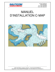
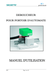
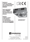
R-SERIES (R5, R6, R8)
Instructions Manuel
TECHNICAL CHARACTERISTICS
R5
R6
R8
Working range
From 2,4mm to 4,0mm Ø All
materials and 4,8mm Ø Aluminum
From 2,4mm to 4,8mm Ø All
materials
From 4,0mm to 6,4mm Ø All
materials
From 3/32'' to 5/32'' Ø All materials From 3/32'' to 3/16'' Ø All materials From 5/32'' to 1/4'' Ø All materials
and 3/16'' Ø Aluminum
Weight
1,30kg – 2,87lbs
1,50kg – 3,11lbs
1,74kg – 3,84lbs
5 to 7 bar – 75 to 105lbs
5 to 7 bar – 75 to 105lbs
16mm – 0,630''
18mm – 0,709''
313mm x 305mm
316mm x 315mm
6 months
6 months
Operating air pressure
5 to 7 bar – 75 to 105lbs
Usable stroke
14mm – 0,551''
Dimensions
305mm x 274mm
Warranty
6 months
Safety Instructions:
–
–
–
–
–
–
–
–
–
–
–
This instruction manual must be read by any person installing, operating, or servicing this tool.
Never dismantle the tool without first having thoroughly studied the instructions given in this User
manual.
Always use the tool in accordance with the specified safety instructions. Direct any queries
regarding optimal and safe operation or use of the tool to our compagny.
The safety instructions must be made clear to all persons involved.
Never connect the tool to any medium other than compressed air. Set the air pressure between 73
and 101 pounds.
Do not use the tool other than placing break stem rivets.
The tool must be maintained in a safe working condition at all times and examined at regular
intervals for damage and function by trained competent personnel. Do not dismantle this tool
without prior reference to the maintenance and service instructions.
Always disconnect the airline from the tool inlet before attempting to maintenance and service.
Do not operate the tool that is directed towards any person or the operator.
When using the tool, the wearing of safety glasses is suggested, by the operator and others in the
vicinity to protect against rivet stem ejection.
Only use hydraulic oil approved by the manufacturer. Please note: Never use brake fluid.
Air supply requirements
All tools are operated with compressed air in the range of 5 to7 bar (75 to 100 psi). We recommend the use of
pressure regulators and filtering systems on the main air supply. These should be fitted within 3 meters of the
tool to ensure maximum tool life and minimum tool maintenance.
Air supply hoses should have a minimum working pressure rating of 150% of the maximum pressure produced
in the system or 10 bar (150 psi), whichever is the highest. Air hoses should be oil resistant, have an abrasion
resistant exterior and should be armoured where operating conditions may result in hoses being damaged. All
air hoses must have a minimum bore diameter of 6.4 millimeters (1/4 inch).
Operation
Determine the size rivet that you are going to use. To change the nosepiece remove it from rivet tool using
wrench included. Select the nosepiece that corresponds to the size rivet you are using and screw nosepiece
clockwise onto the rivet tool head. Meanwhile, check the right pusher (part #7) before operating. Use right size
pusher included which can avoid several spines from obstructing in the tube together after pulling down by
jaws.
1) Attach air line to air supply.
2) Turn on the vacuum system by turning the hex nut/vacuum adjuster nut (part #28) counter-clockwise.
(See Figure 1)
3) Insert a blind rivet into nosepiece. Direct the riveter with rivet to the hole needed to be operated then
pull the trigger. The stems automatically reverse to the collector and the work is done.
Caution:
• The rivet will be held in place by the vacuum system. If rivet falls out of the nosepiece, vacuum is not
strong enough. To increase volume of vacuum, turn the hex nut/vacuum adjuster nut counter-clockwise.
(See Figure 1). To turn it off, turn it clockwise.
• If operating without the nail collector, please wear goggles or turn off the vacuum.
Figure 1
Oiling
It is important that the tool be properly lubricated. Every 10,000 cycles the tool should be oiled with lubricating
oil. There may be insufficient oil if the stroke of the tool is too small for proper installation. Without proper
lubrication the tool will not work properly and parts will wear prematurely.
1. Keep the tool upright during all operations. Connect the tool to the air supply. Please note: don't
press the trigger.
2. Unscrew the oil fill screw (part #37) from the body using the Allen wrench included.
3. Fill the syringe (included) with hydraulic oil.
4. Screw the filled syringe in the oil fill screw hole. Then slowly inject the oil into the tool (Make sure
no air is injected.) Adequate oil has been added as soon as resistance is sensed. The excess oil will
flow back when the syringe is released if more oil is added than necessary. (Fig 2)
5. Unscrew and remove the syringe from the body.
6. Screw the oil fill screw into the hole using the Allen wrench.
7. Wipe off any excess oil.
To test oil level, press trigger 2-3 times. Insert rivet into nosepiece (use the largest diameter rivet that tool
accepts). Check to see if rivet mandrel can be inserted completely into nosepiece – head of rivet must touch
nosepiece. If rivet cannot be completely inserted into tool, too much oil has been added and some must be
removed. To remove excess oil, unscrew oil fill screw approximately ¼ turn. Once the tool is properly adjusted
tighten the oil fill screw firmly with Allen wrench and wipe off any excess oil. When the oil fill screw is
unscrewed, oil will seep from the chamber. After the rivet mandrel is full seated into the nosepiece, the oil level
is then ready for operation.
Figure 2
Jaw cleaning
Every 10,000 cycles the jaws of the tool should be cleaned and oiled. Disconnect the air supply. To access jaws
(part #6), remove the head (part #3) to expose the jaw case (part #5). To remove jaw case from pulling
mechanism, use 2 wrenches (included). Jaws will be under slight spring pressure from the jaw pusher (part #8).
Separate the jaw case from pusher. Jaws will be loose. Clean jaws with a wire brush. Place a small dab of
multi-purpose lithium grease on the outside of jaws (not serrated side). Return jaws into jaw case ensuring
proper placement of jaws. All serrated faces should be touching each other.
Figure 3
A5 , A6 , A8
LISTE DES PIECES ET SCHEMA
PARTS LIST AND DIAGRAM
NO. DE
LISTE
MODELES D'OUTIL
NOUVEAU CODE
DESCRIPTION
ENGLISH
LIST
NUMBER
TOOL MODELS
NEW PART NUMBER
FRANCAISE
DESCRIPTION
01
R5, R6
R0124
TETE DE PIECE 3/32
3/32 NOSEPIECE
01
R5, R6
R0132
TETE DE PIECE 1/8
1/8 NOSEPIECE
01
R5, R6, R8
R0140
TETE DE PIECE 5/32
5/32 NOSEPIECE
01
R5, R6, R8
R0148
TETE DE PIECE 3/16
3/16 NOSEPIECE
01
R8
R0164
TETE DE PIECE 1/4
1/4 NOSEPIECE
01
R5, R6
R0124A
TETE DE PIECE 3/32 ALLONGE
3/32 ELONGATED NOSEPIECE
01
R5, R6
R0132A
TETE DE PIECE 1/8 ALLONGE
1/8 ELONGATED NOSEPIECE
01
R5, R6, R8
R0140A
TETE DE PIECE 5/32 ALLONGE
5/32 ELONGATED NOSEPIECE
01
R5, R6, R8
R0148A
TETE DE PIECE 3/16 ALLONGE
3/16 ELONGATED NOSEPIECE
01
R8
R0164A
TETE DE PIECE 1/4 ALLONGE
1/4 ELONGATED NOSEPIECE
02
R5, R6, R8
R02
JOINT TORIQUE
O'RING
03
R5, R6, R8
R03
CANON
HEAD
04
R5, R6, R8
R04
JOINT TORIQUE
O'RING
05
R5, R6, R8
R05
CARTER DE MACHOIRE
JAW CASE
06
R5, R6
R06
MACHOIRES (3 PIECES)
JAWS (3 PARTS)
06
R8
R068
MACHOIRES (3 PIECES)
JAWS (3 PARTS)
07
R5, R6
R07A
POUSSOIR DE MACHOIRES (2.4/3.2)
JAW PUSHER
07
R5, R6, R8
R07B
POUSSOIR DE MACHOIRES (4.0/4.8)
JAW PUSHER
07
R8
R07C
POUSSOIR DE MACHOIRES (4.8/6.4)
JAW PUSHER
08
R5, R6, R8
R08
RESSORT POUSSOIR DE MACHOIRES
JAW PUSHER SPRING
09
R5, R6, R8
R09
ANNEAU AUTOBLOCANT
LOCK RING
10
R5, R6, R8
R10
JOINT TORIQUE
O'RING
11
R5, R6
R11
UNION DU CARTER
JAW HOUSING COUPLER
11
R8
R118
UNION DU CARTER
JAW HOUSING COUPLER
12
R5, R6
R12
CONTRE-ECROU
SET NUT
12
R8
R128
CONTRE-ECROU
SET NUT
13
R5, R6
R13
JOINT TORIQUE
O'RING
13
R8
R138
JOINT TORIQUE
O'RING
14
R5, R6
R14
JOINT TORIQUE TEFLON
TEFLON O'RING
14
R8
R148
JOINT TORIQUE TEFLON
TEFLON O'RING
15
R5
R155
POIGNEE HYDRAULIQUE
HYDRAULIC SECTION
15
R6
R156
POIGNEE HYDRAULIQUE
HYDRAULIC SECTION
15
R8
R158H
POIGNEE HYDRAULIQUE
HYDRAULIC SECTION
16
R5
R165
JOINT TORIQUE
O'RING
16
R6
R166
JOINT TORIQUE
O'RING
16
R8
R168
JOINT TORIQUE
O'RING
17
R5
R175
JOINT TORIQUE TEFLON
TEFLON O'RING
17
R6
R176
JOINT TORIQUE TEFLON
TEFLON O'RING
17
R8
R178
JOINT TORIQUE TEFLON
TEFLON O'RING
18
R5
R185
PLONGEUR HYDRAULIQUE
HYDRAULIC PLUNGER
18
R6
R186
PLONGEUR HYDRAULIQUE
HYDRAULIC PLUNGER
18
R8
R188H
PLONGEUR HYDRAULIQUE
HYDRAULIC PLUNGER
19
R5, R6, R8
R19
RESSORT DE RETOUR
RETURN SPRING
20
R5, R6
R20
JOINT TORIQUE
O'RING
20
R8
R208
JOINT TORIQUE
O'RING
21
R5, R6
R21
TUBE DU VACUUM
VACCUM TUBE
21
R8
R218
TUBE DU VACUUM
VACCUM TUBE
22
R5, R6
R22
SIEGE DU TUBE DU VACUUM
VACCUM TUBE SEAT
22
R8
R228
SIEGE DU TUBE DU VACUUM
VACCUM TUBE SEAT
23
R5, R6, R8
R23
JOINT TORIQUE
O'RING
24
R5, R6, R8
R24
JOINT TORIQUE
O'RING
25
R5
R255
ENSEMBLE COUVERCLE SCELLANT
SEALING LID ASSEMBLY
NO. DE
LISTE
MODELES D'OUTIL
NOUVEAU CODE
DESCRIPTION
ENGLISH
LIST
NUMBER
TOOL MODELS
NEW PART NUMBER
FRANCAISE
DESCRIPTION
25
R6, R8
R25
ENSEMBLE COUVERCLE SCELLANT
SEALING LID ASSEMBLY
26
R5
R265
JOINT TORIQUE
O'RING
26
R6, R8
R26
JOINT TORIQUE
O'RING
27
R5, R6, R8
R27
JOINT TORIQUE
O'RING
28
R5, R6
R28
VIS D'AJUSTEMENT DU VACUUM
VACUUM ADJUSTER NUT
28
R8
R288
VIS D'AJUSTEMENT DU VACUUM
VACUUM ADJUSTER NUT
29
R5
R295
AMORTISSEUR DU MANDRIN
BREAKNAIL
29
R6, R8
R29
AMORTISSEUR DU MANDRIN
BREAKNAIL
30
R5
R305
RECUPERATEUR DE MANDRIN
MANDREL COLLECTOR
30
R6, R8
R30
RECUPERATEUR DE MANDRIN
MANDREL COLLECTOR
31
R5
R315
SILENCIEUX
SILENCER
31
R6, R8
R31
SILENCIEUX
SILENCER
32
R5
R325
COUVERT DU SILENCIEUX
SILENCER COVER
32
R6, R8
R32
COUVERT DU SILENCIEUX
SILENCER COVER
33
R5, R6, R8
R33
JOINT TORIQUE
O'RING
34
R5, R6, R8
R34
JOINT D'ETANCHEITE
GASKET
35
R5, R6, R8
R35
VIS A TETE HEXAGONALE
HEX HEAD SCREW
36
R5, R6, R8
R36
RONDELLE D'ETANCHEITE
BLEED SCREW SEAL
37
R5, R6, R8
R37
VIS DU RESERVOIR D'HUILE
OIL REFILL SCREW
38
R5, R6, R8
R38
CROCHET
HOOK
39
R5, R6, R8
R39
JOINT D'ETANCHEITE
SEALING GASKET
40
R5, R6, R8
R40
RACCORD POUR L'AIR
AIR TIE-IN
41
R5, R6, R8
R41
ANNEAU D'ETANCHEITE
SHROUD RING
42
R5, R6, R8
R42
CONDUIT D'AIR
AIR TUBE
43
R5, R6, R8
R43
ANNEAU PROTECTEUR
PROTECTIVE RING
44
R5, R6, R8
R44
GACHETTE
TRIGGER
45
R5, R6, R8
R45
BIELLE
CONNECTING ROD
46
R5, R6, R8
R46
POUSSOIR DE LA SOUPAPE
VALVE PUSHER
47
R5, R6, R8
R47
TIGE DE LA BIELLE
CONNECTING ROD PIN
48
R5, R6, R8
R48
TIGE DE LA GACHETTE
TRIGGER PIN
49
R5, R6, R8
R49
VIS POUR POIGNEE
HANDLE SCREW
50
R5, R6, R8
R50
POIGNEE (GAUCHE)
HANDLE (LEFT)
51
R5, R6, R8
R51
POIGNEE (DROITE)
HANDLE (RIGHT)
52
R5, R6
R52
JOINT TORIQUE
O'RING
52
R8
R528
JOINT TORIQUE
O'RING
53
R5
R535
TIGE DE LA SOUPAPE A AIR
AIR VALVE ROD
53
R6
R536
TIGE DE LA SOUPAPE A AIR
AIR VALVE ROD
53
R8
R538
TIGE DE LA SOUPAPE A AIR
AIR VALVE ROD
54
R5, R6
R54
JOINT TORIQUE
O'RING
54
R8
R548
JOINT TORIQUE
O'RING
55
R5
R555
RESSORT DE LA SOUPAPE
VALVE SPRING
55
R6
R556
RESSORT DE LA SOUPAPE
VALVE SPRING
55
R8
R558
RESSORT DE LA SOUPAPE
VALVE SPRING
56
R5, R6, R8
R56
JOINT TORIQUE
O'RING
57
R5, R6, R8
R57
BASE DE LA SOUPAPE
VALVE BASE
58
R5, R6, R8
R58
JOINT TORIQUE
O'RING
59
R5, R6, R8
R59
BILLE EN ACIER
STEEL BALL
60
R5, R6, R8
R60
RESSORT SCELLANT
SEALING SPRING
61
R5, R6, R8
R61
JOINT TORIQUE
O'RING
62
R5, R6, R8
R62
ECROU SCELLANT
SEALING NUT
63
R5, R6, R8
R63
JOINT TORIQUE
O'RING
64
R5, R6, R8
R64
CONNECTEUR
CONNECTOR
65
R5, R6, R8
R65
JOINT TORIQUE
O'RING
NO. DE
LISTE
MODELES D'OUTIL
NOUVEAU CODE
DESCRIPTION
ENGLISH
LIST
NUMBER
TOOL MODELS
NEW PART NUMBER
FRANCAISE
DESCRIPTION
66
R5
R665
MANCHON HYDRAULIQUE
HYDRAULIC ROD
66
R6, R8
R66
MANCHON HYDRAULIQUE
HYDRAULIC ROD
67
R5
R675
JOINT TORIQUE
O'RING
67
R6, R8
R67
JOINT TORIQUE
O'RING
68
R5
R685
JOINT TORIQUE TEFLON
TEFLON O'RING
68
R6, R8
R68
JOINT TORIQUE TEFLON
TEFLON O'RING
69
R5, R6, R8
R69
CONTRE-ECROU
SET NUT
70
R5
R705
CORPS DU CYLINDRE A L'AIR
AIR BODY CYLINDER
70
R6
R706
CORPS DU CYLINDRE A L'AIR
AIR BODY CYLINDER
70
R8
R708H
CORPS DU CYLINDRE A L'AIR
AIR BODY CYLINDER
71
R5, R6, R8
R71
ECROU DE LA CHAMBRE A L'HUILE
OIL CHAMBER NUT
72
R5
R725
TIGE DU PLONGEUR A L'AIR
AIR PLUNGER ROD
72
R6
R726
TIGE DU PLONGEUR A L'AIR
AIR PLUNGER ROD
72
R8
R728
TIGE DU PLONGEUR A L'AIR
AIR PLUNGER ROD
73
R5, R6
R73
SOURDINE
DAMPING RING
73
R8
R738
SOURDINE
DAMPING RING
74
R5, R6, R8
R74
JOINT D'ETANCHEITE
GASKET
75
R5, R6
R75
PISTON
PISTON
75
R8
R758
PISTON
PISTON
76
R5, R6
R76
JOINT TORIQUE DU PLONGEUR
AIR PLUNGER O'RING
76
R8
R768
JOINT TORIQUE DU PLONGEUR
AIR PLUNGER O'RING
77
R5, R6, R8
R77
ECROU
NUT
78
R5, R6
R78
JOINT TORIQUE
O'RING
78
R8
R788
JOINT TORIQUE
O'RING
79
R5, R6
R79
COUVERT DU CORPS
CYLINDER LID
79
R8
R798
COUVERT DU CORPS
CYLINDER LID
80
R5
R805
BASE EN CAOUTCHOUC
RUBBER BASE
80
R6
R806
BASE EN CAOUTCHOUC
RUBBER BASE
80
R8
R808
BASE EN CAOUTCHOUC
RUBBER BASE
81
R5, R6, R8
R81
VIS
SCREW
82
R5, R6, R8
R82
SILENCIEUX
SILENCER
For any questions, feel free to contact us:
Tec-N-Tec Inc.
8244 Pascal Gagnon
Montreal, QC
H1P 1Y4
Tel: (888)832-7777
Fax: (888)832-0282
Email: [email protected]
Please visit our website at:
www.tec-n-tec.com