1
®
®
Science Equipment for Education Physics
LABORATORY EQUIPMENT : : ·
4
–
7
MEASUREMENTS : : ·
8
–
17
FLUID AND GASSES : : ·
18
–
25
MECHANICS : : ·
26
–
39
WAVES, VIBRATIONS AND SOUND : : ·
40
–
56
HEAT : : ·
57
–
64
OPTICS : : ·
65
–
90
MAGNETISM : : ·
91
–
98
ELECTRICITY : : ·
99
–
137
ENERGY : : ·
138
–
143
RADIOACTIVITY/ATOMIC PHYSICS : : ·
144
–
154
CHEMISTRY/BIOLOGY : : ·
155
–
165
SOFTWARE : : ·
166
EXPERIMENTS : : ·
167
–
193
ALPHABETIC/NUMERICAL INDEX : : ·
194
–
200
Physics
Chemistry
Biology
Science/Technology
Lab Equipment
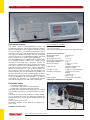
Physics Equipment for Today and
Tomorrow
Frederiksen has been developing and producing physics equipment for more than half
a century. Physics teachers in Denmark and
around the world cooperate closely with Frederiksen in the continuing evolution of new,
improved and more versatile equipment to
meet changing needs.
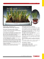
Just as Newtons’s laws of motion are universally valid, we aim to provide world-wide
users with science equipment which is
- suitable for any curriculum in any country
- well-designed and of high quality
- competitively priced
In order to supply you with nothing but the
best, we depend on your feedback with comments and suggestions. Whether you want to
order new equipment or suggest improvements, please get in touch with us. If you seek
advise on applications, feel free to contact
your Frederiksen dealer for straightforward
information backed by experience.
Development and production
High quality, user-friendly design and pedagogical value for students are keywords
guiding our product development group. At
the same time we do our best to optimise
design for producing equipment for you at the
most competitive prices.
Our highly qualified, well trained staff keep up
to date on the newest production techniques
so that our production department can make
maximum use of modern technology.
®
Science Equipment for Education Physics
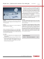
New Frederiksen WEB page
www.frederiksen.eu
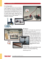
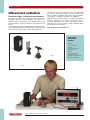
We have recently launched our new WEB page
www.frederiksen.eu.
It is active in full extent in Danish language and
we are working on a new English version also.
In the near future you will find interesting news
about Frederiksen and our products here !
Science Equipment for Education Physics
®
4
:: LABORATORY EQUIPMENT
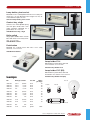
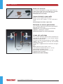
Laboratory equipment
0001.00
Retort stand base
A-shape cast iron with stoved enamel finish. Length of
feet 200 mm, with 10 mm dia. hole and fixing screw for
retort stand rods dia. 10 mm, supplied with rubber feet.
Weight: 2.0 kg.
0001.00 Retort stand base
Retort stand base
Stump-shaped cast iron with stoved enamel finish,
designed to accept 10 mm. dia. retort stand rods, complete with thumb screw.
Weight: 0.43 kg.
0004.00
0004.00 Retort stand base
Retort stand base
Stump-shaped cast iron with stoved enamel finish,
designed to accept 10 mm. dia. retort stand rods, complete with thumb screw.
Weight: 0.57 kg.
0004.10
0004.10 Retort stand base
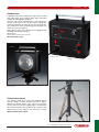
Retort stand base
Tripod in cast iron with stoved enamel finish.
Designed to accept 10 mm. dia. retort stand
rods, complete with fixing screw and
rubber feet. Weight: 1.0 kg.
0006.10
0006.00 Retort stand base
0006.00
Retort stand base
Tripod in cast iron with stoved enamel
finish, with vertical tubing equipped
with thumb screw. Designed to accept
10 mm dia. retort stand rods.
Weight: 1.20 kg.
0008.40-.60
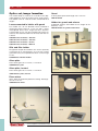
0006.10 Retort stand base
0008.00-.30
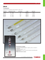
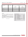
Retort stand rods
Made of polished solid stainless steel 10 mm dia.
No.
Length
Diameter
0008.00
0008.10
0008.20
0008.30
0008.40
0008.50
0008.60
150
100
75
50
60
25
10
12/10
12/10
12/10
12/10
10
10
10
®
cm
cm
cm
cm
cm
cm
cm
mm
mm
mm
mm
mm
mm
mm
Science Equipment for Education Physics
LABORATORY EQUIPMENT
::
5
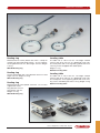
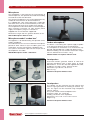
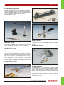
Table clamp
Designed for mounting of retort stand rods to the edge of
a table. The holes can accommodate rods of up to 13
mm in diameter. The maximum clamp opening is 65 mm.
The mass of the clamp is 0.36 kg. The clamp is made of
cast iron with stoved enamel finish.
0016.00 Table clamp
Retort stand base
(incl. rod)
Steel plate 155 x 200 mm in
stoved enamel finish, with
one M10 hole for retort
stand rod of nickel-plated
steel. Retort stand rod 10
mm dia., length 60 cm.
Weight: 2.8 kg.
Table clamp, universal
0016.00
0010.00 Retort stand base
(incl. rod)
0010.00
Designed for securing round or
square retort stand rods up to 25
mm in diameter or plates up to 20
mm thick. The clamp can be
mounted on the edge of a table,
thickness up to 56 mm. Manufactured of cast iron with lacquered
finish. Weight: 1.2 kg.
0016.10 Table clamp, universal
0018.10
0016.10
Clamp
0018.30
Clamp with rounded jaws of light alloy on a 10 mm. dia.
steel shaft. Enables articles from 20 to 55 mm. dia. to be
clamped securely, with cork lined jaws.
Total length: 240 mm. Weight: 0.2 kg.
0018.40
0018.10 Clamp
Clamp
Clamp with diecast lacquered angular jaws on a 10 mm.
dia. steel shaft. Enables articles from 10 to 40 mm dia. to
be clamped securely, with cork lined jaws.
Total length: 200 mm. Weight: 0.22 kg.
0018.00
0018.30 Clamp
Clamp
Universal Clamp
Clamp with overlapping jaws on a 10 mm dia. Steel shaft.
Enables articles from 0-40 mm dia. To be clamped securely. Jaws are coated with soft PVC. Length 230 mm.
Weight: 0,14 kg.
Clamp with overlapping jaws of lacquered aluminium on
a 10 mm dia. steel shaft. Enables articles from 2 to 85
mm dia. to be clamped securely, with cork lined jaws.
Equipped with a double-threaded quick-tightening arrangement for ease of use.
Total length: 230 mm. Weight: 0.18 kg.
0018.00 Clamp
0018.40 Universal Clamp
Science Equipment for Education Physics
®
6
:: LABORATORY EQUIPMENT
Bosshead
Double Bosshead in lacquered aluminium with two slots
at right angles to take round or square rods from 7 to 16
mm dia.
Total length: 130 mm. Weight: 0.18 kg.
0023.00
0023.00 Bosshead
Universal bosshead
Double Bosshead made of lacquered aluminium, with
four slots at right angles to take round or square rods up
to 16 mm dia. With 2 angular screws.
Overall length: 55 mm.
0023.10 Universal bosshead
0023.10
0023.20
Suspension hook
Support rod clamp, rotatable
This rotatable double rod clamp is made of pressure cast
zinc and finished with lacquer. For support rods from 718 mm in diameter. Total length 155 mm. Weight: 0,174
kg.
Suspension hook made of lacqured aluminium, hook in
nickel-plated brass. Clamps on retorts stand rods from 7
to 16 mm dia.
Total length: 130 mm. Weight: 0.1 kg.
0027.00 Suspension hook
0023.20 Support rod clamp, rotatable
0027.00
Support rod clamp with 10 mm
diameter hole
Designed for support of equipment using a 10 mm rod.
Lacquered, pressure cast zinc. Can be mounted on retort stand rods with a diameter from 7 to 18 mm. Total
length: 80 mm. Weight: 0,077 kg.
0028.00 Support rod clamp
0028.00
®
Science Equipment for Education Physics
LABORATORY EQUIPMENT
::
7
0038.20
0038.00
0038.10
Heating ring
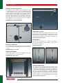
Leveling table
Manufactured of nickel plated steel with a clamp for
mounting on retort rod clamps from 6 - 15 mm in diameter. Ring diameter: 60 mm. Total length: 190 mm. Weight:
0,15 kg.
The table size is: 165 x 130 mm. The height variation
range is from 62 to 277 mm. It is produced using stainless steel plates with a fast regulating spindle and 8 ea.
securing screws. Supplied with rubber pads.
Weight: 1.7 kg.
0038.00 Heating ring
0036.00 Leveling table
Heating ring
As item 0038.00 but with a ring diameter of 80 mm. Total
length 205 mm. Weight: 0,22 kg.
0038.10 Heating ring
Heating ring
Manufactured of nickel plated steel with a 10 mm dia.
support rod mount.
Ring diameter: 80 mm.
Total length: 240 mm.
Weight: 0,17 kg.
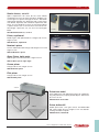
Leveling table
The table size is: 200 x 200 mm. The height variation
range is from 62 to 276 mm. It is produced using stainless steel plates. Fast regulating spindle with 8 ea. securing screws and rubber pads. Mass: 2.6 kg. Weight: 2.4 kg.
0036.10 Leveling table
0038.20 Heating ring
0036.00
0036.10
Science Equipment for Education Physics
®
8
:: MEASUREMENTS, MASS AND LENGTH
Measurements
1038.00-.80
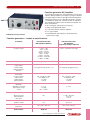
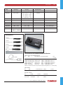
Dynamometers
The SF dynamometers are available in 9 different ranges
covering the range from 0.1 to 100 Newtons. Use the
dynamometers to measure an applied force or apply a
measured force. These high quality metric dynamometers are precise, durable, and calibrated in Newton.
The graduations are easy to read and the resolution is
2% of full scale.
No.
Range
1038.00
1038.10
1038.20
1038.30
1038.40
1038.50
1038.60
1038.70
1038.80
0-0.1
0-0.2
0-1
0-2
0-5
0-10
0-20
0-50
0-100
N
N
N
N
N
N
N
N
N
Resolution
Colour Code
Dimension in mm
0.002
0.004
0.02
0.4
0.1
0.2
0.4
1.0
2.0
Silver
Beige
Yellow
Red
Blue
Green
Violet
Orange
Gold
Ø16
Ø16
Ø16
Ø16
Ø16
Ø16
Ø16
Ø20
Ø20
N
N
N
N
N
N
N
N
N
Features
Accuracy:
The Dynamometers provide superb linearity and the 100
mm long scales are sharp and clear for excellent resolution.
Durability:
The spring is sealed in the acrylic tube - it doesn't get
tangled or overstreched.
Zero adjust:
Easy and accurate zero adjust by means of the knurled
screw uppermost on the dynamometer.
Sealed scales:
The scales are inside the acrylic housing so that they
won’t wear off.
Colour coded:
Each dynamometer has it's own colour code and the
max. range printed on the scale.
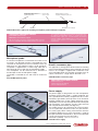
Boxed set of dynamometers
Keeps the right dynamometer for the right purpose at
hand anytime!
Handy foam-lined box with partitions, holds the entire
range of dynamometers 0.1 - 0.2 - 1 - 2 - 5 - 10 - 20 - 50
- 100 Newtons.
The box is also excellent for safe and easy storage.
Box with carrying handle, dimensions: 33 x 27 x 5.5 cm.
1039.00 Boxed set of Dynamometers
1039.10 Foam-lined box only
®
Science Equipment for Education Physics
1039.00
x
x
x
x
x
x
x
x
x
265
265
265
265
265
265
265
310
310
mm
mm
mm
mm
mm
mm
mm
mm
mm
MEASUREMENTS, MASS AND LENGTH
::
9
Measurements, length
and volume
Measuring tape, plast
1400.10
Length: 150 cm. Marked in mm and cm.
1400.00 Measuring tape, plast
Measuring tape, metal
Length: 200 cm. Marked in mm and cm. Metal measuring tape in automatic roll-up housing.
1400.00
1400.10 Measuring tape, metal
Tape measure, surveyor model
Surveyor model, length 20 m. Centimeter and meter
graduation. Tape made of fibre glass armed nylon.
Box made of high impact ABS
plastic. Auto winding.
1400.20 Tape measure
Ruler
Wood. Length: 50 cm, graduated in
millimeters and centimeters. Horizontal reading.
1405.00 Ruler
1400.20
Ruler
Wood. Length: 1 m, graduated in millimeters and centimeters. Horizontal reading.
1405.10 Ruler
1405.00
1405.10
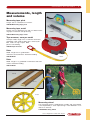
1428.00
Measuring wheel
The measuring wheel is supplied with a handle, and each rotation
is accompanied by a “click” representing 1 meter. Marked in 2 cm
and 10 cm intervals.
1428.00 Measuring wheel
Science Equipment for Education Physics
®
10
:: MEASUREMENTS, MASS AND LENGTH
Caliper gauge, plastic
Measuring length 130 mm. Overall length 170 mm. Equipped with depth gauge and vernier scale for reading to
1/10 mm.
1440.10
1440.00 Caliper gauge, plastic
Caliper gauge, steel
Measuring length 120 mm/5 inches, with depth gauge
and vernier scale for reading to 1/10 mm.
Overall length 18.5 cm.
1440.00
1440.10 Caliper gauge, steel
Caliper gauge, stainless steel
High quality caliper gauge with measuring length 140
mm/5.5 inches. With vernier scale for reading to 1/20
mm, depth of stop and locking system.
1440.20 Caliper gauge, stainless steel
1440.20
1450.50
Liter measuring pitcher
This plastic measuring pitcher is marked in units of volume. There is a marking for each 10 ml. Manufactured in
clear, shock resistant polyethylene.
1465.00 Measuring pitcher, 1⁄2 liter
1465.10 Measuring pitcher, 1 liter
Micrometer screw gauge
Maximum measuring length 25 mm. Precision 0.01 mm.
A precision micrometer with girder section frame, specially hardened and ground screw, locknut and ratchet.
Supplied in protective case.
1450.50 Micrometer screw gauge
1465.00-.10
®
Science Equipment for Education Physics
MEASUREMENTS, MASS AND LENGTH
::
11
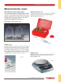
Measurements, mass
Beam balance with support stand
Balance masses set
This sensitive beam balance is supplied with a support
stand. It is provided with a knife edge bearing in hardened steel, a screw adjustment for zeroing, a 28 cm long
indicator needle with scale, loose 120 mm diameter
weighing pans and a plate for buoyancy experiments.
The sensitivity of the balance is 50 mg.
Height: 35 cm, Depth: 20 cm, Width: 40 cm.
Set comprising 16 masses from 10 mg to 50 g. Supplied
complete in a plastic box incl. Nikkelplated forceps.
0955.30 Balance masses set
0916.00 Balance with support stand
0916.00
0955.30
Digital scale
For quick weight measurements indoors or out. Weighing range 0-2 kg (accuracy 0-1 kg/1 g, 1-2 kg/2 g). Battery powered with an automatic power-down feature.
The weight is supplied with a 135 x 135 mm weighing
plate. Solidly built and suitable for use out of doors.
Zeroing possible in the entire weighing range. The weight
is supplied without a battery (use 1 ea. 3510.10).
Digital scale
Weighing range 0-200 g with 0,1 g accuracy. Automatic
power-down. Battery powered. Batteries included.
1028.07
1028.15 Digital scale
1028.15
Science Equipment for Education Physics
®
12
:: MEASUREMENTS, MASS AND LENGTH
Specific gravity
Specific gravity cubes
1500.00
Dimensions 10 x 10 x 10 mm. For illustration of the
specific gravity of different materials. The set comprises
of six different materials: Al, Fe, Zn, Cu, Pb and wood.
Supplied in a plastic box.
1500.00 Specific gravity cubes
Specific gravity cylinders
6 different materials: Fe, Al, Pb, Zn, wood and cork. 3 of the
cylinders have the same weight i.e. Al, Pb and Zn (41 gr.).
Two of these cylinders have the same diameter. The remaining cylinders have different volumes and shapes. The
cylinders are easy to measure. Supplied in a plastic box.
Specific gravity cylinder
Brass cylinder for determining specific gravity and
measuring volumes. Height 28 mm.
1510.80 Specific gravity cylinders
1510.00 Specific gravity cylinders
1510.00
1510.80
Specific gravity cylinders
1510.10
3 different materials with the same volumes.
Al, Cu and brass.
Diameter 20 mm, height 31.5 mm.
Supplied in a plastic box.
1510.10 Specific gravity cylinder
Specific gravity cubes
6 different materials each in three different sizes.
Delivered in a plastic box.
1500.10 Specific gravity cubes
®
Science Equipment for Education Physics
1515.00
MEASUREMENTS, MASS AND LENGTH
::
13
Pycnometer, calibrated
This device is used to measure the
density of fluids. It is sometimes called
a specific gravity bottle. Manufactured
of glass with a tightly fitting ground
glass stopper with a fine hole in it.
Calibrated. Volume: 50 ml.
1520.00
520.00 Pycnometer, calibrated
1520.10
Pycnometer, uncalibrated
The same device as 1520.00 but uncalibrated. Volume: 25 ml.
1520.10 Pycnometer, uncalibrated
Areometer
A device for finding the specific gravity of liquids. Density range: 0.7001.000 g/cm3. Accuracy 0.005 g/cm3.
Total length: 300 mm.
1530.00 Areometer
Areometer
Density range: 1.000-2.000 g/cm3.
Accuracy 0.010 g/cm3. Total length:
300 mm.
1530.10 Areometer
Areometer
Density range: 0.750-0.840 g/cm3 with thermometer.
1530.20 Areometer
Areometer with
thermometer
For determination of the salt
content of seawater. Temperature table supplied. Total
length: 265 mm.
1530.90
1530.20
1530.30 Areometer with
thermometer
Alcohol meter
1530.30
1 - 100 vol %. Total length:
300 mm.
1530.90 Alcohol meter
1530.10
Science Equipment for Education Physics
®
14
:: MEASUREMENTS, TIME
Demonstration stopwatch
Easy to read from a remote distance.
Quartz clockwork with dials.
Range 0-60 sec 0-60minutes.
Diameter 110mm, weight 375 ,g.
Supplied with battery
1495.20 Demonstration stopwatch
1485.40
Digital stopwatch, Phoenix
1495.20
The stopwatch has an LCD-display with 6 ea. 8.5 mm/7
mm digits. Functions: start/stop/reset, addition, intermediate times /splits. Double measurement of two times
intervals closely following one another. Standard clock (2
x 12 hours AM/PM). Date.
1485.40 Digital stopwatch, Phoenix
Stopwatch
Seconds scale 0-30 s. Minute scale 0-15 min. Accuracy
1/10 s. Three function buttons
for start, stop and reset.
1485.00
1485.00 Stopwatch
Digital stopwatch
Low cost digital stopwatch with LCD display with 5 mm
high digits. Functions: start/stop/reset, addition, intermediate times/splits, standard time and date.
1485.15
Digital stopwatch
Digital countdown clock
LCD digital countdown clock with 35 mm high digits.
Alarmfunction.
1492.05 Digital countdown clock
1492.05
1485.15
®
Science Equipment for Education Physics
MEASUREMENTS, TIME
::
15
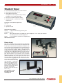
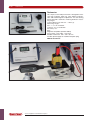
Student timer
●
●
●
●
●
Time measurements from 0.03 ms to 27 hours
Measurement precision 0.01 ms
Start/stop by connecting
microphones (2485.10), photocells (1975.50)
or ordinary 4 mm safety jack leads
Manually controlled stopwatch option
Simple operation – excellent for student
experiments
Particularly well-suited for experiments
such as:
●
●
The free fall
Speed of sound
2002.60
Technical specifications:
Display:
5 digit LED with floating decimal point
Resolution: 0.01 ms
Inputs:
DIN-5 pole connectors for photocells and microphones, 4 mm safety jack leads for
free fall experiment and other apparatus
Power:
6 ea. AA batteries or power-line adapter (incl.)
2002.60 Student timer
Photocell unit
The unit is suitable for the measurement of pendulum
periods, time interval measurements for experiments on
an air track, measurements of periods of rotation, etc.
The unit consists of a photocell which is illuminated via a
one millimeter aperture by light from a light emitting diode. A red LED (light emitting diode) is provided next to
the light source to indicate that the light source is on. A
green LED near the photocell indicates when the receiver
is illuminated. The photocell unit is provided with two 6pole DIN-connectors for connection to the electronic
counter no. 2002.50 or 2002.60 and serial connection to
additional photocell units, when signals are to be sent to
the same input connection on the counter. The unit is
manufactured in rugged plastic with threads for horizontal or vertical mounting using
the 10 mm diameter mounting
rod provided. A connector
cable for the electronic counter is also provided. The maximum distance between the
photocell and the light source
is 90 mm. Dimensions:
B x H x D: 160 x 120 x 28 mm.
Mass: 450 g.
1975.50 Photocell unit
including cable and
mounting rod
1975.50
Science Equipment for Education Physics
®
16
:: MEASUREMENTS, TIME
Free fall apparatus
This apparatus is designed to be used with an Electronic
Counter to determine the fall time for a freely falling steel ball. The apparatus consists of a release mechanism
which also acts as the start switch, a strike plate which
acts as the stop switch and gold-plated steel balls. The
release mechanism is provided with two dia. 4 mm banana plug connectors for connecting safety dia. 4 mm
banana plug leads to the Counter start switch input. A 10
mm diameter mounting rod for supporting the mechanism on a lab stand is supplied. The strike plate is also
provided with two dia. 4 mm banana plug connectors for
attaching this unit to the Counter stop input.
Exper
iment
E-101
1980.10 Free fall apparatus
1980.10
Microphone
2485.10
Exper
iment
E-102
The microphone is well-suited for the measurement of
sound frequencies, the speed of sound and the recording of sound for Fourier transformation.
The sensitive microphone is very small and therefore
very suitable for measurements of sound interference.
It is supplied with a one meter cable with a 3-pole DIN
connector which can be connected directly to the electronic counter type 2002.50 or
student timer type 2002.60. The
microphone can also be connected to an oscilloscope or other
measuring instrument via a type
2515.60 power supply. The frequ2485.10
ency range is 20-20.000 Hz. Supplied with 10 mm diameter support rod. Dimensions: Length 105
mm, greatest diameter 30 mm.
2485.10 Microphone without
stand
2482.00
Clapper board
This clapper board is ideal for producing the sharp
sound pulse required for measuring the speed of sound.
Produced with two hinged hardwood blocks.
Dimensions: 27 x 50 x 300 mm. Mass: 280 g.
2482.00 Clapper board
®
Science Equipment for Education Physics
MEASUREMENTS, TIME
::
17
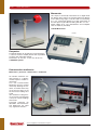
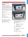
Electronic
counter
• Multiple function
capability.
• Microprocessor
controlled.
• User-friendly.
• High accuracy.
This microprocessor
controlled eight-digit counter can be used for measurement of time intervals, periods, revolutions per second,
frequency, pulses, etc. The indicator shows the units of
measurement, and the display indicates the input terminal being used. Start/stop terminals for attachment of
microphones, photocells, free fall equipment, etc. are
provided. There is a connector for attachment of a GMcounter for measurements of radioactivity with selectable gate times. The counter is provided with an easyto-read LED display and a logically arranged control
panel making the apparatus highly suitable for demonstration experiments as well as for student lab exercises.
Memory is provided for storing measured values as well
as an RS-232 port for connection to a computer.
A computer program for analysis of the collected data is
provided. Time intervals down to 1 millisecond, and
frequencies up to 2 MHz can be measured.
Technical Specifications
General:
8 digit 7 segment LED 25 mm high
Power supply:
230 VAC, 50 Hz
Time measurement,
start-stop:
from 0.01 ms to 100 s,
resolution 0.01 ms
Collisions: passage
times, min/max:
0.01 ms/100 s, resolution 0.01 ms,
but 1 ms for passage times over 10 s.
Memory storage for 4 values, 2 from
each photocell or 3 values from one
and one value from another.
Acceleration:
passage times
min/max:
0.01 ms/100 s, resolution 0.01 ms,
but 1 ms for passage times over
10 s. Memory storage for passage
time A, passage time B, and the time
from A to B.
Period:
From 0.01 ms to 10 s.
Memory storage:
50 values
Frequency:
0.01 Hz - 1 kHz, resolution 0.01 Hz
1kHz - 10 kHz, resolution 0.1 Hz
10 kHz - 2.5 MHz, resolution 1 Hz
Counter:
1 count - 10 million counts,
1 count resolution
Measurement times: 1 S, 10 s, 60 s and 100 s.
Gate times:
2.5 MHz / 0.4 ms
Memory storage:
50 values
Dimensions:
LxHxW: 405 x 116 x 205 mm. 3.7 kg
Compatible
Measurement of pendulum period.
Exper
iment
E-102
Measuring the speed of sound.
2002.50 Electronic counter
Science Equipment for Education Physics
®
18
:: FLUID AND GASSES
Water powered air pump
Polypropylen plastic pump. Connection threads for 1/2"
and 3/4" pipes. Sealing fitting with “O”-ring. Supplied
with a reverse flow valve. Total length: 270 mm.
0690.20 Water powered air pump
Water powered air pump
0690.20
Chrome plated brass with sealing fitting with 1/2" pipe
thread. Supplied with reverse flow valve. Conical tube
connection fitting 11-12 mm. Total length: 140 mm.
0690.30 Water powered air pump
Water powered air pump
Manometer of chrome plated brass with a scale from 01 bar. Accuracy 0.025 bar. Also as 0690.30. Total length:
160 mm.
0690.40 Water powered air pump
0690.30
0690.40
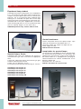
Vacuum pump
Electric rotary vane vacuum pump. The pump is equipped
with an automatic gas ballast valve which will open in case
of condensable steams suction. In such cases the gas ballast valve will operate to avoid condensation inside the
pump and evacuate steam or fumes including oil.
Technical data:
Mains operated:
Free air displacement:
Ultimate vacuum:
Motor power:
Fittings sizes:
Oil:
Net mass:
Dimensions L x W x H:
220 V AC, 50 Hz
27 l/min.
5 x 10 -1 Pa
1/3 HP
1/4”G
220 ml
12.5 kg
336 x 123 x 255 mm
0695.25 Vacuum pump
Oil for vacuum
pump
For refilling or replacing
the operating oil in Vacuum Pump 0695.20
0695.25
0695.30
Vacuum Oil 1 liter
0695.30
®
Science Equipment for Education Physics
FLUID AND GASSES
::
19
Vacuum meter
The meter scale goes from 0 to 1.0 bars at 0.05 bar intervals. The meter diameter is 50 mm. It is supplied with a tube connector fitting.
0700.10 Vacuum meter
Hand-powered vacuum pump
0700.10
This hand-powered vacuum pump uses a piston.
It is supplied with a one-way valve and tube connection fitting.
Ultimate vacuum down to 0.1 atm.
0715.00 Hand-powered vacuum pump
Vacuum grease
Silicone grease for high vacuum applications. The grease
is approved for temperatures from -40 to +250 degrees C.
The can contains 60 grams.
0715.00
0710.20
0710.20 Vacuum grease
Pascals vases apparatus
These vases are used to show that pressure in a liquid is
a function of depth only. The vases are four differently
shaped glass vessels which may be attached to a base
which has a diaphragm sensitive to pressure and connected to a dial. Bottom plate with support: 235 x 130
mm, height incl. glass tube: 290 mm. Pressure sensor
with scale.
1610.00 Pascals vases apparatus
1610.00
1640.10
Archimedes cylinder set
This equipment is for demonstrating Archimedes law. It consists of a plastic cylinder supplied with an eye and a transparent container with nylon loops for suspension on a newton meter or a balance. The plastic cylinder is immersed in water, and
the buoyancy of the water opposes the gravitational force on the cylinder with a
magnitude corresponding to the weight of the displaced liquid. This can be compensated for by filling up the container with water, for the internal volume of the
container corresponds exactly to the volume of the plastic cylinder.
1640.10 Archimedes cylinder set
Science Equipment for Education Physics
®
20
:: FLUID AND GASSES
Liquid level
apparatus
1645.00
To show that the level of
liquid in connected vessels is constant regardless of the size or shape
of the vessels. The tubes
are mounted on a plastic
base, diameter 120 mm.
Overall height 230 mm.
1630.00 Liquid level
apparatus
Overflow container, archimedes’ beaker
A body is immersed in the cylindrical beaker. Diameter:
37 mm, height: 147 mm. The displaced liquid runs out
through an overflow tube and can be collected. Used to
demonstrate Archimedes law.
1645.00 Overflow container, archimedes’ beaker
1630.00
1732.00
1730.00
Air pressure demonstration jar
A glass cylinder 120 x 120 mm high with ground bottom
edge for use on a pump plate, and flange on top for attaching a rubber membrane. Including Rubber Membrane.
1730.00 Air pressure demonstration jar
Rubber membrane
Dimension: 220 x 220 x 0,2 mm
1625.10 Rubber membrane
Collapsible metal can
To demonstrate the pressure of the atmosphere.
1732.00 Collapsible metal can
Hydraulic press
The device consists of two glass syringes of 2 and 20 ml.
They are connected with a short PVC tube. Pressing one
cylinder causes the other to move. The distances which
the cylinders move are inversely proportional to the area
ratios.
1650.00 Hydraulic press
®
Science Equipment for Education Physics
1650.00
FLUID AND GASSES
::
21
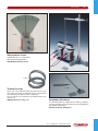
Pelton turbine with generator
Assembled, operational model which by means of water
or air jets is capable of producing electricity to light a filament lamp. Turbine housing of plexiglass. Turbine wheel
of black plastic. As generator is used an ordinary 6 V AC
bicycle dynamo.
Turbine housing: H. 195 mm, W. 170 mm, D. 100 mm.
1705.00 Pelton turbine with generator
1660.00
Cartesian devil
Used to demonstrate liquid pressure. Hollow glass
figure, height ca. 45 mm.
1660.00 Cartesian devil
1735.00
1705.00
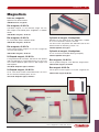
Magdeburg hemispheres
For demonstration of the pressure exerted by the atmosphere. Made of chrome
plated brass with rubber gasket. Provided with venting screw and connector
with non-return valve. Diameter 110 mm,
mass 711 g.
1735.00 Magdeburg hemispheres
Magdeburg hemispheres,
student version
Made of black rubber. Package with 4 pairs.
1735.20 Magdeburg hemispheres,
student version
1735.20
Gasket for 1735.00
Rubber Gasket
1735.01 Gasket for 1735.00
Science Equipment for Education Physics
®
22
:: FLUID AND GASSES
Manometer
This simple, user-friendly manometer has a digital readout display which shows the measured pressure directly
in kPa. Measuring range: 0-200 kPa with an uncertainty
of +/-2%. Connection directly to a tube connection on
the front panel is possible for tubing with dia. 5-7 mm.
Power supply: 6 ea. 1,5 V AA batteries or line adapter
3550.10-3550.20 (included).
1770.00 Manometer
1770.00
1740.00
Dasymeter
For demonstration of air buoyancy when placed in
a vacuum receiver. Hollow plastic ball suspended
on beam with adjustable weight.
Dimensions: H. 135 mm, L. 120 mm, W. 65 mm.
1740.00 Dasymeter
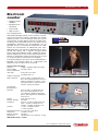
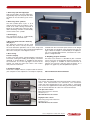
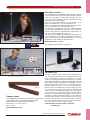
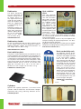
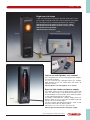
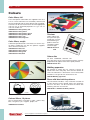
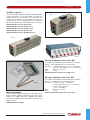
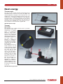
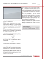
Demonstration multimeter
Manometer · pH-meter · thermometer · multimeter
To maintain maximum student interest in a demonstration requires student involvement.
This new Demonstration
Multimeter ensures student
interest by allowing the students, no matter where they
are in the class room, to see
the instrument readings first
hand.
Your students no longer have to just take your word for
it, they can see the readings
themselves.
Designed especially for
education, this Demonstration Multimeter has eight
very significant features.
®
Science Equipment for Education Physics
3867.70
FLUID AND GASSES
::
23
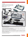
1. Extra large (45 mm high) digits
And since the digits are LEDs (Light Emitting Diodes) they can easily be seen from
the back of the classroom (up to 8 meters).
2. Extra large units symbols
The units symbols (hPa, V, pH, °C, A, Ω
and Hz) ensuring that no student is confused as to what is being measured. A
bright 30 mm LED matrix makes this possible. Switching functions automatically
set the correct units symbol.
3. Autoranging
The measuring range is automatically
matched to the measured value.
4. One instrument for both chemistry
and physics
This particular instrument will be used
day after day since it not only measures
the usual electronic quantities such as volts, amps and
ohms, but it also measures pressure pH and temperature
from minus 50 to plus 1200 degrees Celsius.
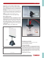
5. Back facing
teacher's display
In most cases the teacher stands behind the measuring
instrument, making the reading af the display somewhat
awkward. A second display is available for the back of
the instrument. Its 14 mm high digits ensure that the
teacher can read the value even when a few meters
away from the instrument.
6. Computer Output
An RS 232 C output makes it a simple matter to connect
your computer to the experiment. The output is optically
isolated from the instrument input so there is no danger
of damaging the computer when working with high voltages. Since the output is controlled by a microprocessor, using standard data formats, connection to a computer is straightforward.
8. Graphing program available
For those cases where it is desirable to plot a function
versus time (such as temperature during a chemical reaction) a program is available to take measurement at
specific time intervals and then plot the points on a
graph. This graph may also be plotted on a printer.
3867.70 Demonstration multimeter.
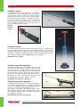
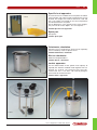
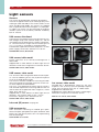
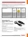
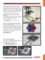
Pressure sensors
IM-131410
The sensors are connected to the DIN-connectors of these instruments. Then measurements can commence. The instruments
make their own identification of the sensor which is connected.
The sensors are supplied with a tube fitting to which plastic tubing
with an internal diameter of 5 or 6 mm can be connected.
IM-131510
Low pressure sensor:
Measuring range: 0-1300 hPa
Accuracy: 1%
IM-1314.10 Pressure sensor
High pressure sensor:
Measuring range: 500-7000 hPa
Accuracy: 1%
IM-1315.10 Pressure sensor
Science Equipment for Education Physics
®
24
:: FLUID AND GASSES
Barometer, mini
1786.00
For the measurement of
barometric pressure in
millibars and millimeters
of mercury with an
adjustable dial to record
the previous observation. The diameter of the
barometer is only 67.5 mm
1771.00
which makes it possible to put
it inside the “Glass with tube connector” product 1786.00 to simulate over and under pressures in the glass container. The barometer can
be calibrated using an adjustment screw.
1771.00 Mini barometer
Student bell jar
This bell jar provides a vacuum chamber for students to perform many
experiments: Watching a balloon expand. Warm water boil as air is pumped from the chamber. Observing that a suction cup no longer sticks when
the jar is evacuated. Hand-Powered Vacuum Pump no. 0715.00 or a 100 ml
plastic syringe and valves can be used for evacuating the Jar. To measure
the pressure in the Student Bell Jar no. 1771.00. Barometer can be used
since it fits into the Bell Jar.
1786.00 Student bell jar
1780.00
Air pump plate
This plate is used with a bell jar for demonstration experiments involving low pressure. The plate is made of PVC
and supplied with rubber feet. There is a vacuum connection fitting with a valve and a thumb screw for the
return air. Two standard 4 mm jack connectors are provided with 4 mm jack connections available inside the
jar. Tube fitting diameter: 10 mm. Plate diameter: 235
mm, height: 40 mm, mass: 1.3 kg.
1780.00 Air pump plate
Bell jar with knob
Used in conjunction with pump plate no. 1780.00 for the
production of vacuum. Arranged in heavy glass with
ground flange. Diameter 180 mm, height 250 mm.
1785.10 Bell jar with knob
1785.10
®
Science Equipment for Education Physics
FLUID AND GASSES
::
25
1810.10
1810.00
1805.00
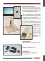
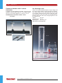
Boyle-Mariotte apparatus
This device is used to demonstrate the connection between pressure and volume at constant temperature.
The apparatus consists of a graduated cylinder with a
piston. The cylinder acts upon a manometer via a narrow
passage. The cylinder is supplied with a screw valve.
The manometer diameter is 100 mm. The length of the
apparatus is 350 mm.
1805.00 Boyle-Mariotte apparatus
Exper
iment
E-201
Plastic cylinder with Piston
For demonstration of the relation between volume and
pressure at constant temperature (Boyle-Mariotte). The
cylinder is graduated and provided with a 1 cm2 piston
as well as strap and hook, allowing it to be acted on by
a dynamometer.
1810.00 Plastic cylinder with Piston 1 cm2
1810.10 Plastic cylinder with Piston 2 cm2
Wind speed meter, digital
1876.05
This electronic wind speed meter meter has an easily
readable digital display. The instrument can display wind
speeds directly in km/hour, m/s, knots or feet/minute.
The anemometer itself is mounted with low-friction ball
bearings inside a protective housing. A 110 cm long cable connects the anemometer unit with the readout unit
where the wind speed can be read directly in the units
selected. The wind speed data is updated 2.5 times per
second. Anemometer operation is independent of orientation.
Technical specifications:
Measuring range
Resolution
0.8 - 30.0 m/s
+/- 0.1 m/s
2.8 - 108 km/h
+/- 0.1 km/h
1.6 - 58 knots
+/- 0.1 knot
160 - 5900 feet/minute +/- 10 feet/min
Accuracy
+/-3% of full scale, +/- 2 digits
Power supply
1 ea. 9 V block battery
1876.05 Wind speed meter, digital
Science Equipment for Education Physics
®
26
:: MECHANICS
Mechanics
1905.00
Centre of gravity plates
Set consisting of 2 aluminium plates, approx. 250 mm
long. Equipped with holes for suspending in corners and
centre of gravity, with marks for the centre of gravity
lines. For suspension the handle with pin no. 1905.10
may be utilized.
1900.00 Centre of gravity plates
Demonstration balance
For demonstration of the weight principle and momentum. Made of nickel-plated brass and equipped with 30
holes numbered from the middle for suspension of
weights.
1905.00 Demonstration balance
1900.00
Handle with pin
For suspension of no. 1905.00 and 1900.00.
1905.10 Handle with pin
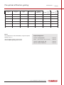
Weights with hooks
Used in conjunction with demonstration balance no.
1905.00, made of nickel-plated brass with stamped
mass indication.
1910.00
1910.10
1910.20
1910.30
1910.40
1910.50
1910.60
1910.70
1910.80
Mass
Mass
Mass
Mass
Mass
Mass
Mass
Mass
Mass
100
160
150
140
130
120
115
110
115
g
g
g
g
g
g
g
g
g
1910.00-1910.80
0960.40
1920.00
Iron weights
0960.30
0960.20
0960.10
These calibrated weights are made of galvanized iron.
They are provided with an eye-hook, and they are marked with the value of the mass.
0960.10
0960.20
0960.30
0960.40
Mass
Mass
Mass
Mass
500 g,
1000 g,
2000 g,
5000 g,
45 mm
60 mm
75 mm
100 mm
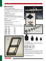
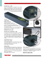
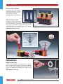
Stability apparatus
To illustrate how stability depends upon the location of
the center of gravity with respect to the base. The position of the centre of gravity is well defined and can be
changed easily. Materials: Enamelled steel bars with
plastic centres. Base: 100 x 120 mm, Height: max. 260
mm.
1920.00 Stability apparatus
®
Science Equipment for Education Physics
MECHANICS
Friction block
Friction block, area
This wooden block with a square
cross section has surfaces with rubber, felt, sandpaper and wood. Supplied with a hook at one end. Size:
60 x 60 x 300 mm.
This item is for demonstration of the
dependence of friction upon area.
Two different areas can be used with
the same mass. Supplied with a
hook at one end.
Size: 300 x 50 x 26 mm.
1925.10 Friction block, area
1925.00 Friction block
::
27
1925.00
1925.10
1938.10
1920.10
Double cone with ramp
In contrast to what one expects, the double cone
appears to roll uphill when placed at the bottom of the
ramp. But is this also the case? Stimulate your students’
curiosity with this simple, classical paradox - and try it
with your colleagues in the teachers’ lounge !
Inclined plane
1920.10 Double cone with ramp
Inclined plane and friction board 1000 mm x 150 mm
Inclined plane made of aluminium.
With holder for dynamometer.
Air cushion disc with balloon
1938.10 Inclined plane and friction board
For demonstrating the influence of frictional forces. The
disc consists of a circular plastic plate with an air hole
and with a fitting for a rubber stopper with a hole for
mounting a balloon. Air from the balloon passes through
the hole in the plate, causing the disc to hover on a
cushion of air. Acrylic plate diameter 115 mm.
1945.00 Air cushion disc with balloon
Balloons in package
1945.10 Round balloons, 100 ea.
1945.10
1945.00
Science Equipment for Education Physics
®
28
:: MECHANICS
Exper
iment
E-301
Exper
iment
E-302
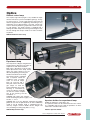
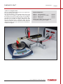
Linear Air Track
No other systems have the same high quality for study of linear dynamics.
Because of extreme low friction the results will be up to 25 % better compared to similar
systems based on trolleys where higher friction and inertia of wheels occur.
Air track
Air track
For checking smooth uniform motion smoothly
accelerated motion, Newtons Second Law, elastic
and inelastic collisions.
The air track is made from a large square aluminium extrusion in conjunction with a supporting
“U” channel. A series of 7 screws allow adjustment of the air track to a typical linearity of ±0.03
mm. The air track rests on three rubber feet, two
of which can be height-adjusted.
The overall length of 2 meters provides a working
length of 1.9 meters. The buffer at the end of the
track as well as the carts are supplied with 4 mm.
diameter holes for fixing plug-in units. All units
have approximately the same center of gravity and
the same mass of 10 g.
For accurate length measurements each side of
the track has a scale graduated in mm.
A repeatable launch is desirable in many collision
experiments. The electric launcher permit’s launching of air track carts with repeatable impulses,
varying the impulses as needed, and even launching two carts simultaneously.
®
Standard version. The complete air track consists of the
following parts: Air track 2000 mm, standard accessories
in a plastic box, and two carts.
1950.00 Air Track
Air track
As no. 1950.00 but supplied with a “C” channel on the
side for fixing the photocell unit no. 1975.10.
1950.10 Air Track
Science Equipment for Education Physics
1950.00-.10
MECHANICS
Standard air track
accessory set
::
29
Standard Air Track
Accessory Set
Supplied in a box with a lid and fitted partitions for the
various parts. The set contains the following items:
1960.10
1960.00
Fork
For use along with 1955.10 for elastic collisions in conjunction with the firing mechanism no. 1952.00. Mass: 10 g.
1955.00 Fork with plug connectors, 3 ea.
1955.00
Holder with plate
1955.10
For elastic collisions with 1955.00. Mass: 10 g.
1955.10 Holder with plate and plug connectors, 3 ea.
Holder with needle
1955.30
1955.20
For inelastic collisions with 1955.30. Mass: 10 g.
1955.20 Holder with needle and plug connectors, 1 ea.
Tube with wax
1955.40
1965.00
For inelastic collisions with 1955.20.
1955.30 Tube with wax and plug connectors, 1 ea.
Holder with hook
Used as pulling hook for acceleration experiments.
Mass: 10 g.
1955.50
1955.60
1955.40 Holder with hook and plug connectors, 1 ea.
Aperture 25 mm
Used as aperture for the photocell unit for time measurements. Mass: 5 g.
1950.02
1955.60 Aperture with plug connectors, 25 mm, 2 ea.
Aperture 100 mm
Used as aperture for photocell unit for time measurements. Mass: 10 g.
1955.50 Aperture with plug connectors, 100 mm, 1 ea.
Cart for air track
Made of black lacquered aluminum. Supplied with
mounting holes for accessories. Length: 125 mm. Mass:
170 g.
1960.00 Cart for air track, 2 ea.
Standard air track accessory set
Weight for cart
Additional weights for air track cart no. 1960.00. Mass:
50 g.
As decribed above and supplied in a plastic box with lid.
Cards for Air Track not included.
1950.02 Standard air track accessory set
1960.10 Weight for air track, 4 ea.
Pulley
Low friction ball bearing pulley. Used for acceleration
experiments. Mass: 13 g.
1965.00 Pulley with plug connectors, 1 ea.
Science Equipment for Education Physics
®
30
:: MECHANICS
Extra accessories:
Aperture with notch
Supplied with a notch for actuating start/stop of the electronic counter type 2001.00 and previous versions by
means of photocell units. Starts and stops the counter
on the high to low transition. Measurement length: 25 mm.
1955.80
1955.85
1955.70 Aperture with notch
Aperture with notch for side mounting
Aperture for side mounting on air track cart no. 1960.00.
Supplied with a compensation weight to be placed on
the opposite side of the cart. Supplied with a notch for
start/stop of electronic counter type 2001.00 and earlier
models by means of photocell units. Total mass: 10 g.
Measurement length 20 mm.
1955.70
1963.00
1955.80 Aperture with notch for side mounting
Aperture for side mounting
Aperture for mounting on the side of the cart no.
1960.00. Supplied with a compensation weight to be
positioned on the opposite side of the air track cart. Total
mass: 10 g. Width: 30 mm.
1955.85 Aperture for side mounting
Slot weights with holder
Used for accelerating the air track cart. The set consists
of a 2 g holder, 2 ea. 1 g weights, 1 ea. 2 g weight, 1 ea.
5 g weight, 1 ea. 10 g weight. Total mass: 21 g. This set
permits combinations of masses from 2 g to 21 g.
1963.00 Slot weights with holder
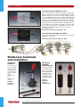
Electric launcher
The set consists of an electromagnet with the anchor
mounted on the air track cart. By mounting the fork with
rubber band (1955.00) in the electromagnet the cart can
be ejected when the current to the electromagnet is
switched off. The force acting on the cart when ejected
can be varied by varying the tension on the rubber band.
There is good repeatability.
The set consists of:
Iron core 20 x 20 x 51 mm with
1964.00
mounting screw (1964.00).
Coil with 400 windings (4625.20)
Anchor with plug connector (1955.90)
4625.20
1955.90
1952.00 Electric launcher
1952.00
Switch box
The box is used to interrupt the current to the firing
mechanism used on the air track. Supplied with a capacitor
and output jack connections to counter no. 2002.50.
1985.00 Switch box
1985.00
®
Science Equipment for Education Physics
MECHANICS
::
31
Photocell unit
This item is for measuring pendulum
swings, time measurements on the air
track, measurements of rotation rates,
etc. The unit consists of a photocell
which receives light transmitted from a
light emitting diode (LED) through a 1
mm aperture. Next to the light source
LED and next to the photocell red and
green LED’s are mounted to indicate
whether a signal is reaching the photocell from the light source and whether
the light source is on. The photocell unit
is provided with two 6-pole DIN-connectors for connection to electronic counter type 2002.50 and extension to additional photocell units if additional signals are to be connected to the same
input on the counter. They are made of
impact-resistant plastic and provided
with threads for vertical or horizontal
mounting with the 10 mm diameter
mounting rod (also supplied). Supplied
with a connection cable to the electronic counter. Maximum distance between the photocell and the LED: 90
mm.
Width: 160 mm, height: 120 mm,
thickness: 28 mm. Mass: 450 g.
1975.50
1975.50 Photocell unit incl. cable
and mounting rod
Photocell unit
Used for timing on the air track. The unit is made especially for mounting on air track no. 1950.10. Provided
with slide indicator and plugs for 2002.50.
1975.15 Photocell unit
1975.15
Science Equipment for Education Physics
®
32
:: MECHANICS
Air switch
1968.00
To be placed between air hose and air
track in order to switch off the air
supply.
1972.00
1967.00 Air switch
Adjustable
endstop
1967.00
Made of anodized aluminium with 4
mm. diameter hole for plug-in units.
1968.00 Adjustable endstop
1969.00
Protective cover for air
track
Protective cover, made of soft plastic
with rim of lead.
1969.00 Protective cover
Coupled harmonic oscillators
You can link up to five Air Track Carts together for the
study of harmonic of coupled harmonic motion, or you
can use a single cart with one or more springs for a
detailed, quantitive study of simple harmonic motion.
Additional you can use Electromechanical Vibrator no.
2185.00 and drive the coupled oscillators at fixed and
measurable frequencies.
The set consist of the following parts:
1969.00 Cart for Air Track 3 ea.
(2 ea. Supplied with the Air Track)
1960.10 Weight for Cart 6 ea.
2155.20 Spring Connectors 6 ea.
1972.00
1972.00 Coupled Harmonic Oscillators
Air blower
1970.50
Extremely quiet air blower with continuously adjustable
speed. The air blower is designed especially for operation of the air tracks no. 1950.00 and 1950.10. Complete
with 1.7 m hose. Mains supply: 220-240 V AC.
Dimensions: 280 x 250 x 210 mm. Mass 5.7 kg.
1970.50 Air blower
Electronic counter
A digital time counter which can be started and stopped
using photocells, electronic switches and pulses. Wellsuited for use for time measurements on the air track,
measuring the time in free-fall experiments, elapsed time
when objects are thrown, etc. It can also be used for
frequency measurement and pulse counting. See additional specifications on page 17.
2002.50
2002.50 Electronic counter
®
Science Equipment for Education Physics
MECHANICS
::
33
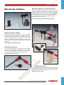
Free-fall tube
Falling bodies apparatus
For demonstrating that the free fall acceleration in a
vacuum is independent of weight and shape of body.
Consists of a acrylic plastic tube 30 x 900 mm. Endcover, stop-cock, magnet, steelball and paper disc.
To illustrate that a body impelled horizontally will fall vertically at the same rate as a similar body allowed to fall
freely. Place two balls one on each end of the swing arm
and push the release. One ball is dropped and the other
is launched horizontally, the simultaneous “click” as both
balls hit the floor at the same time proves the point.
Supplied with 2 19 mm dia. balls in the storage pocket.
Dimensions: L 180 mm, W 170 mm, H 50 mm.
1977.00 Free-fall tube
1990.00 Falling bodies apparatus
1977.00
1990.00
Free fall apparatus
1980.10
Exper
iment
E-101
This apparatus is designed to
be used with an Electronic
Counter to determine the fall
time for a freely falling steel
ball. The apparatus consists
of a release mechanism
which also acts as the start
switch, a strike plate which
acts as the stop switch and
gold-plated steel balls. The
release mechanism is provided with two dia. 4 mm banana plug connectors for connecting safety dia. 4 mm
banana plug leads to the
Counter start switch input. A
10 mm diameter mounting
rod for supporting the
mechanism on a lab stand is
supplied. The strike plate is
also provided with two dia. 4
mm banana plug connectors
for attaching this unit to the
Counter stop input.
1980.10 Free fall
apparatus
Science Equipment for Education Physics
®
34
:: MECHANICS
Steel balls
These balls are used for experiments involving motion
and energy.
Exper
iment
E-303
1992.20
1997.10
1997.20
1997.30
1997.40
1997.50
1997.60
1997.70
1997.80
1997.85
1997.90
Diameter
Diameter
Diameter
Diameter
Diameter
Diameter
Diameter
Diameter
Diameter
Diameter
40 mm
28 mm
25 mm
20 mm
18 mm
16 mm
12 mm
10 mm
6 mm
3,2 mm, 200 pcs.
Glass balls
1999.00 Diameter 16 mm
Curved ball track
1997.00-.90
Used for two dimensional collision experiments. A simple but dependable apparatus for demonstrating elastic
and inelastic collisions in two dimensions. Because the
fall time to the floor is independent of any initial horizontal velocity, the horizontal displacement can be converted to a relative velocity, permitting the momentum to be
computed. In order to obtain the full benefit from this
experiment, students should be familiar with vectors.
The set consists of a curved ball track with mounting
hardware, two 12 mm steel balls, one 12 mm glass ball
and a hollow 25 mm wooden ball. A weight and plumb
line are also supplied.
1992.20 Curved ball track
REQUIRED ACCESSORIES:
1992.10 Easily smudged carbon paper
®
Science Equipment for Education Physics
MECHANICS
::
35
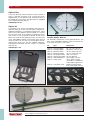
Ticker tape timer
For measuring elapsed time of linear motion. The timer
comprises an AC coil acting on a spring suspended marker plate that in conjunction with a spring loaded ball
(adjustable from the bottom plate) makes dots on a 17.5
mm wide paper tape with the time interval 0.02 sec. 64
mm dia. carbon disc can be used for marking. The ticker
tape timer is made of nickel-plated steel. The top plate
with the AC coil is hinged to the steel body and locked
by means of a magnet.
Exper
iment
E-305
2005.00 Ticker tape timer
Carbon paper discs
2005.70
For the ticker tape timers no. 2005.00. Package of 50
ea. Diameter 64 mm.
2005.30 Carbon paper discs
Tape
17.5 mm wide tape
for the timers no.
2005.00, 360 g
roll.
2005.20 Tape
Rod with mounting bracket
Appropriate for mounting of timer 2005.00 as shown in
the figure. The bracket has a stoved enamel finish and
the rust free steel rod has a 10 mm diameter. Total
length: 230 mm.
2005.70 Rod with mounting bracket
2005.00
Timer tape holder
Drop weight
Nickel-plated iron weight with self tightening locking
mechanism for the tape, for use with the ticker tape timer
no. 2005.00. Diameter: 32 mm. Height: 160 mm.
The holder is for timer tape (2005.20). It is made of black
plastic with ball bearings and a 10 mm diameter mounting rod and bracket of rust free steel.
2005.80 Timer tape holder
2005.40 Drop weight 1 kg, height 160 mm
2005.50 Drop weight 0,5 kg, height 82 mm
2005.60 Drop weight 0,25 kg, height 42 mm
2005.20
20
05
.6
0
2005.40
2005.50
2005.30
2005.80
Science Equipment for Education Physics
®
36
:: MECHANICS
Stroboscope disc
Made af black-lacquered plastic with 1
aperture.
For use with e.g. motor no. 2025.00 and
illuminator.
Diameter 170 mm, hole diameter 8 mm.
2020.00 Stroboscope disc
Stroboscope made of experiment
lamp and stroboscope disc.
Stroboscope disc
Motor with winding shaft
As 2020.00 but with 12 apertures.
This universal motor is for operating units such as strobe discs, color discs, apparatus and models. Furthermore, the motor can be used as a generator in energy experiments, etc. The unit is provided with a sturdy DC motor
with a permanent magnet stator.
A 2 step drive belt shaft is supplied along with a cylindrical winding axle with diameters of 8 and 12 mm. Supplied with a 35 mm 10 mm diameter mounting rod. Total
length: 225 mm. Width: 40 mm. Height: 40 mm. Operating voltage range 0-12 V DC 0-4800 rpm, mass 0.35 kg.
2020.10 Stroboscope disc
2020.10
2025.00 Motor with winding shaft
2020.00
2025.00
2037.00
Drive belt set
Four different flexible, black synthetic rubber drive belts
are supplied. Belt lengths: 240, 289 and 780 mm. The
drive belts are oil resistant.
2037.00 Drive belt set, 4 different belts
®
Science Equipment for Education Physics
MECHANICS
::
37
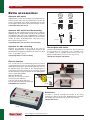
Stroboscope
A portable instrument employing a high intensity xenon
flash tube which gives a brilliant white light, particularly
suitable for photographic purposes.
The flash rate can be regulated from 1.0 to 300.0 flashes per second or 1 to 18 000 rpm. Digital reading with
switch for impulses per second, rpm. and external trigging. Input terminals for external trigging and output terminals for internal triggering.
Mains power supply: 220 V AC/50-60 Hz. Equipped with
threaded hole for stand in base.
Dimensions:
180 x 240 x 120 mm, W x H x D.
2015.60 Stroboscope
2015.50
Back panel view.
2015.60
Front panel view.
2030.16
Photo/video tripod
This tripod is ideal for use with the Stroboscope no.
2015.50. Made of black eloxated aluminium. Adjustable to any desired height - max. 1450 mm. The quick
camera mount fits into the stroboscope’s standard thread. Extremely handy, takes up practically no space when
folded away yet very stable in use. Net mass: 1.750 kg.
2030.16 Photo/video tripod
Science Equipment for Education Physics
®
38
:: MECHANICS
Circular motion apparatus
For experiments with uniform circular motion this setup
is simple and easy to use. Using a small motor a weight
is caused to move in a circle. The mass of the weight, the
rotational speed and the angle the string makes with the
vertical allow the confirmation of the equations of circular motion. The set consists of a small DC motor at the
end of a support rod with connection leads, three different rubber balls and strings with snap locks. Supplied
with laboratory exercise instructions.
2070.00
2070.00 Circular motion apparatus
2085.00
Pulley block in line
Pulley block comprising 2 pulley blocks in line for the
demonstration of the principle of a pulley block. Each
block consists of 3 pulleys in line. Pulleys dia. 34 mm, 40
mm and 47 mm. Length: 175 mm. Mass: 0.27 kg per set.
2095.00
2106.40 Pulley block in line
Pulley block
Set consists of 2 blocks with 3 pulleys for making a
demonstration model of a pulley block. Pulleys 40 mm
dia. Mass: 0.3 kg per set.
Pulley on steel rod
Low friction pulley made of plastic 47 mm dia. Mounted
on a 10 mm dia. fixing rod, length of rod 200 mm. Mass:
0.14 kg.
2106.30 Pulley block
2085.00 Pulley on steel rod
Pulley with clamp
2106.30
Pulley made of plastic 47 mm dia. Supplied with clamp
for clamping on e.g. a retort stand rod.
2095.00 Pulley with clamp
2106.40
Collision apparatus
2115.10
This apparatus is designed to illustrate Newton’s third
law of motion: action and reaction forces act upon different bodies and are oppositely directed. The apparatus
is also suitable for the demonstration of momentum conservation. The collision apparatus is supplied with 5 ea.
25,4 mm diameter nickel coated steel balls suspended
by double strings in a robust wooden frame. Size: length:
227 mm, width: 183 mm, height: 222 mm. Mass: 0.7 kg.
2515.10 Collision apparatus
®
Science Equipment for Education Physics
MECHANICS
::
39
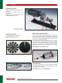
Prandtl’s rotating disc
For demonstrating the principle of the conservation of
angular momentum. A 480 mm diameter metal disc with
ball-bearing axle on base with levelling screws and supporting stool.
Dimensions: Height 150 mm. Weight: 9.5 kg.
2136.00
2135.00 Prandtl’s rotating disc
Bicycle wheel gyro
Suitable for demonstrating the conservation of angular
momentum with a rotating stool or disc. A 500 mm
diameter spoked wheel with plastic lined rim, axle and 2
handles. Supplied with pulley and 1.5 m nylon cord.
2136.00 Bicycle wheel gyro
2135.00
2136.00
Science Equipment for Education Physics
®
40
:: WAVES, VIBRATIONS AND SOUND
Ripple tank
Whether you are dealing with the wave properties of light,
electromagnetic waves, sound or other types of waves,
their behavior is analogous to the behavior of waves on a
water surface.
In a teaching situation water waves have the advantage of
being visible and moving so slowly that students can
observe wave phenomena directly.
Exper
iment
E-401
By taking advantage of the optical properties of water
waves, phenomena, can be enlarged and made visible on
a screen.
The Ripple tank provides a dramatic demonstration of the
general properties of waves and propagation phenomena.
1)
Reflection and refraction. By using the linear dipper bar
plane parallel waves can be produced. The waves
exhibit reflection and refraction when appropriate
barriers are used in the water tank.
2)
Inteference phenomena occur when two point source
dippers generate circular waves. The distance between
the sources and their frequency can be regulated.
3)
Plane parallel waves form point wave sources when
they encounter a double slit formed by three barriers.
4)
The propagation velocity is dependent upon the depth
of the water layer. The transparent lens cross section is
covered by a shallow layer of water.
2211.00 Ripple Tank
1)
2)
3)
4)
Projection
Intense illumination from the strobe light enables the images to be enlarged and projected using several techniques.
On a table it is well-suited for group work e.g. in lab exercises. On a screen it is ideal for classroom demonstrations or
lecture halls.
®
Science Equipment for Education Physics
WAVES, VIBRATIONS AND SOUND
::
41
F
D
E
J
K
B
A
G
C
A
B
H
The vibrator is overloadprotected. The moving parts are controlled by means of a double membrane. Height regulation of
the dippers is continuous using finger screws. The horizontal position can also be adjusted.
The vibrator assembly can also be used to generate waves
on a string, in connection with resonance phenomena on flat
plates and for the demonstration of the states of matter.
I
Vibrator
Wavegenerator in phase with strobelight.
Support with height adjustment
The generator assembly can be adjusted so that the dippers
just touch the water.
C
Ripple tank
D
Wave dampers
E
Glass bottom surface
F
Stroboscope
G
Projection mirror
H
Projection screen
I
Footers with adjustment screws
J
Power supply
Manufactured of reinforced plastic.
Impede the reflection of incident waves.
Easy to clean and scratch resistant.
The light source is a white LED (3W). The LED has a very long
lifespan,espimated up to 100.000 hours, thus a change of
light source will not be relevant.
Scratch resistant and easy to clean with protective backing
plate.
A specially produced projection screen ensures optimum
sharpness.
The Ripple tank is supported by three legs to ensure a stable
setup and to permit exact regulation of water depth.
The Ripple Tank is delivered with a mains adapter.
K
Wave dippers
The standard set includes various dippers and lens profiles.
Science Equipment for Education Physics
®
42
:: WAVES, VIBRATIONS AND SOUND
10
6
11
14
24
8
9
13
Content of box item no.:
18 – 19– 21 –22 – 23
12
7
Box
16
26
25
20
17
1
15
5
The Ripple Tank comprises the
following individual parts:
11) Ripple Tank (2210.33) . . . . . . . . 1 pcs.
12) Detachable legs (2210,1013) . . 3 pcs.
13) Plate fitting (2210,1013) . . . . . . 1 pcs.
14) Frosted glass plate (2210,5093) 1 pcs.
15) Acrylic block, concave (2210.28) 1 pcs.
16) Acrylic block, convex (2210.29) 1 pcs.
17) Acrylic block, rectangular pcs.
20) (2210.30) . . . . . . . . . . . . . . . . . . 1 pcs.
20) Dipper for parallel waves w. plane
20) wave attachment (2210.25) . . . 1 pcs.
16) Fixing rods for Strobe-unit
20) (2210.62) . . . . . . . . . . . . . . . . . . 2 pcs.
20) (2210,2202) . . . . . . . . . . . . . . . . . 5 pcs.
17) Traverse f. Strobe-unit
22) Barrier, long (2210.26) . . . . . . . 2 pcs.
18) Strobe-unit (2211.01) . . . . . . . . 1 pcs.
19) Power Supply (3550.50) . . . . . . 1 pcs.
3
21) Single dipper (unmounted)
23) Barrier, short (2210.27) . . . . . . . 1 pcs.
The ripple tank set is supplied complete in a fiber box segmented for storing
the components and with complete
user instructions.
2210.50 Ripple Tank, Complete
24) Pipette flask w. special solvent
20) (2210.31) . . . . . . . . . . . . . . . . . . 1 pcs.
10) Vibration Generator (2185.00) . 1 pcs.
25) Connection cable for Vibration
11) Mounting pin 2185.06) . . . . . . . 1 pcs.
20) Generator (1100.75) . . . . . . . . . 1 pcs.
12) Holder for lever arm (2185.05) . 1 pcs.
26) Remote Control (1100.80) . . . . 1 pcs.
13) Lever Arm w. pivot (2210.32) . . 1 pcs.
14) Height adjust unit (2185.07) . . .1 pcs.
Electromechanical
vibrator
The vibrator generates mechanical vibrations when
used with a signal generator as e.g. catalog no.
2500.00 or 2501.50. The input signal is supplied to a
coil which is mounted in a magnetic field from a cylindrical magnet. The unit is fuse-protected.
It is supplied with a lock which protects moving parts
while changing accessories. It is supplied with mounting hardware, a string holder and extra fuses.
Max. input: 6 V/1A.
Dimensions: 100 mm diameter x 120 mm.
Mass:
1.26 kg
2185.00 Electromechanical Vibrator
®
4
19) Double dipper (2210.23) . . . . . . 1 pcs.
15) Mirror (2210,1011) . . . . . . . . . . 1 pcs.
20) (2210.62) . . . . . . . . . . . . . . . . . . 1 pcs.
2
18) Single dipper (2210.22) . . . . . . 1 pcs.
Science Equipment for Education Physics
2185.00
WAVES, VIBRATIONS AND SOUND
Vibrator accessories:
::
43
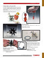
Chladni plates
For use with 2185.00. A thin layer of fine sand is spread
over the plate, and resonance patterns ("Chladni" figures)
can be observed at certain frequencies. The plate resonances are audible.
2185.25
2185.20 Resonance plate, square
2185.25 Resonance plate, circular
Flat springs for resonance experiments
Various lengths. For use with the 2185.00. Fundamental
frequencies at 11, 15, 21, 36 and 50 Hz can be readily
observed. Interesting standing waves can be seen up to
300 Hz and heard up to 900 Hz.
2185.30 Flat Springs for resonance experiments
Longitudinal Wave Spring
2185.20
155 mm long and 27 mm Diameter. Springkonstant 4,7
N/m.
2155.50 Longitudinal Wave Spring
2185.30
2155.50
2185.40
2185.10
Piano wire ring
For use with 2185.00 for demonstrating the relationship
between frequency and the number of vibrational nodes.
Ring diameter: 290 mm.
2185.10 Piano wire ring
Rubber string
2 meters. For use with 2185.00 for demonstrating
standing waves.
2185.40 Rubber string
Science Equipment for Education Physics
®
44
:: WAVES, VIBRATIONS AND SOUND
Gas model with piston
For use with the 2185.00. Ball bearings in motion represent gas molecules which lift a plastic piston due to repeated
collisions. The model is supplied with the piston, balls and a support for placing the apparatus on an overhead
projector.
2185.15
2185.55 Gas model with piston
Solids.
Gas in piston.
The gaseous state.
Brownian motion.
Boiling liquid.
Lissajous' apparatus
This apparatus is actually a simple oscilloscope. A
mirror is mounted on a moveable steel ball held by
two strips of spring steel. The two steel strips are
spring loaded at one end and each controlled by a
2185.00 vibrator at the other. By regulating the oscillations with the two vibrators, one can control the
motion of the mirror in two mutually perpendicular
directions and thus control the laser beam reflected
by the mirror. The light source can be a gas laser, a
diode laser or similar light source. The vibrators, signal generators and light source are not included.
2185.60
2185.60 Lissajous' apparatus
ADDITIONAL EQUIPMENT NEEDED
2 ea. Electromagnetic vibrators (2285.00)
2 ea. Signal generators (e.g. 2500.50)
1 ea. Laser (2885.00)
®
Science Equipment for Education Physics
WAVES, VIBRATIONS AND SOUND
::
45
HE-NE LASER FOR INTERFERENCE EXPERIMENTS
HE-NE LASER 1 MW
Safety filter and shutter.
2885.00
Standard thread for
objectives.
The laser emits light with a wavelength of 632.8
nanometers. The emitted light is coherent, i.e. wave
fronts propagate in the same phase over a large distance
compared with ordinary light sources. The emitted light is
highly directional and the beam diameter at the laser is
about 0.5 mm increasing very gradually at increasing
distances from the laser. The light emitted is not uniformly polarized but changes its polarization at random around the direction of propagation. Light from the laser is
well-suited to demonstrations of optical interference. If a
line grating is placed in the laser beam, the interference
pattern will be clearly visible on a projection screen. The
laser can be used for a wide range of applications in geometrical optics, holography, communication etc.
He-Ne laser, modulated,
1 mW
Laser like the 2885.00 but with the option of
modulating the light beam. The laser is provided
with a BNC-connector for connection to a signal generator, CD-player or similar signal source. The light beam
intensity will then vary with the applied signal. Well suited for demonstration of optical communication using
photodetector no. 4895.50.
Maximum modulation frequency: 1 MHz.
2885.20 He-Ne laser, modulated, 1 mW
2885.00 He-Ne Laser, 1 mW
2885.10 He-Ne Laser, 2 mW
Inteference pattern
4895.50
Photodetector
The photodetector is provided with a photo diode which
can convert laser light intensity values to an electrical signal. The signal can be directed to the built in loudspeaker
or be used for measurements via the analog and digital
output connections. The photodetector can be used for
demonstrating communication over a laser beam, fiber
optic communication, plotting of interference patterns,
etc. The maximum frequency is 1 MHz.
model for overhead projector
The set consists of two transparent plastic plates with
printed wave front patterns for point sources on each
plate. If the plates are placed on top of one another and
slightly displaced, an
interference pattern will
appear. The pattern can
readily be projected
onto a large viewing
screen using an overhead projector.
3235.00 Inteference
pattern set
3235.00
4895.50 Photodetector
Science Equipment for Education Physics
®
46
:: WAVES, VIBRATIONS AND SOUND
Wavelength of light apparatus
The apparatus is designed to measure the wavelength of
light by studying the interference pattern from a double
slit. The device contains a built in 12 V auto lamp with a
holder for color filters and a millimeter scale with phosphorescent moveable markers. The emitted light is
viewed at a distance of about 3 meters through a double
slit. The viewer then directs a co-worker to adjust the
markers on the millimeter scale so that the distance
between them corresponds to 10 interference maxima.
Afterwards the distances can be measured and the
wavelength of the light can be calculated. The equipment
is well-suited to student lab exercises. Red and blue
color filters and a double slit are provided.
Power source required: 12 V AC/DC, 1.3 A.
3240.00
3240.00 Wavelength of light apparatus
Function generator - DC amplifier
Frequency counter
Compatible
2501.50
Three functions are built into a single
instrument with a digital display. The
simple and well-organized operating
panel makes the unit well-suited
for demonstration experiments
and for student experiments with
vibrations, waves and much
more.
Function generator
Sine, triangular and square wave
signals with a broad, continuous
frequency range are provided.
Digital fine-tuning of frequency and amplitude are provided. The BNC output signal connection (0-20 Vpp) is
short-circuit protected. Up to 10 W of output power are
available via the amplifier. It is possible to demonstrate
frequency modulation by connecting an external signal.
DC amplifier
The short-circuit proof 10 W power amplifier has a frequency range from 0 - 50 kHz.
The amplifier can be used to amplify signals from the
function generator or from external sources.
The input of external signals is via BNC connectors with
an impedance of 10 kΩ, and the output signal is accessible via safety-type banana jack connectors.
®
Frequency counter
The meter is fully automatic, and it can measure external
frequencies from 0.1 Hz to 150 kHz.
Serial computer interface
The instrument is supplied with a RS-232 serial computer interface which makes it possible to perform remote control and readout of the instrument. This can be
accomplished via the standard terminal program in
Windows or by means of the program Datalyse.
2501.50 Function Generator
Science Equipment for Education Physics
WAVES, VIBRATIONS AND SOUND
::
47
Function generator DC Amplifier
The function generator has a broad frequency range and
a built-in power amplifier. The frequency range is divided
into eight regions which can be adjusted and read off the
adjustment knob scale. It is possible to perform frequency modulation (FM) and external control of frequency.
The function generator is well-suited for use by both students and teachers.
● Sine, triangular and square wave signals.
● Short-circuit protected inputs.
● 10 W external/internal power amplifier.
● TTL signal output.
● FM modulation and frequency sweep within the
performance range.
2500.50
2500.50 Function generator
Function generators - technical specifications:
Instrument
Function Generator
DC Amplifier 2500.50
Function Generator
DC Amplifier
Frequency Counter 2501.50
Frequency region
0,1 Hz – 1 Hz
1 Hz – 10 Hz
10 Hz – 100 Hz
100 Hz – 1000 Hz
1 kHz – 10 kHz
10 kHz – 100 kHz
100 kHz – 1000 kHz
1 MHz – 10 MHz
0,1 Hz – 100 kHz in one range
Signal type
Sine, triangular, square wave
Sine, triangular, square wave
± 5.5 V pp and TTL 50 W < 1.3%
0-20 V pp 600 W typically 0.5 %
DC - 50 kHz at -3 dB
10 W RMS / 4 W
± 10 Vpp
10 K W
DC - 50 kHz at -3 dB
10 W RMS / 4W
± 10 Vpp
10 K W
± 0-5 V
± 10 Vpp
DC - 10 kHz
± 0-5 V
Measuring region
Input impedance
Max. input
No
0.1 Hz - 150 kHz
200 k W
± 100 V
Computer output
No
RS 232 C
297 x 225 x 118 mm
297 x 225 x 118 mm
2500.50
2501.50
Signal output:
Output voltage
Output impedance
Distortion
DC Amplifier
Frequency Range
Output Power
Output Voltage
Input Impedance
Modulator:
Modulation signal FM
Input voltage, sweep
Sweep
Frequency counter:
Dimensions
Order number
Science Equipment for Education Physics
®
48
:: WAVES, VIBRATIONS AND SOUND
Resonance pipe for sound experiments
Exper
iment
Exper
iment
E-4 08
E-407
This resonance pipe provides many options for working
with sound waves:
● Examine standing waves in a pipe open at both ends,
closed at both ends or open at one end and closed at
the other. Examine standing waves in a pipe closed at
both ends while various gasses are pumped into the
pipe.
● Vary the length of the half-open pipe by means of a
piston (provided).
● The pipe consists of a plexiglas pipe with two end
pieces with attachments for gas flow. There is a loudspeaker in one end.
● Dimensions: Length 100 cm. Diameter 7 cm.
Standing waves in a
closed pipe.
Standing waves in
CO2.
Standing waves in a
pipe with open end.
Standing waves in a pipe
with both ends open.
Regulation of the
length of the air
column.
A tuning fork or a
loudspeaker can be
used as the
sound source.
®
Science Equipment for Education Physics
WAVES, VIBRATIONS AND SOUND
End-plug with speaker, hose-connector,
miniature phone plug connector
(female) and fuse wire.
mm-scale
Resonance tube,
Ø 7 cm x 100 cm.
::
49
End-plug with hose-connector,
and guide for Microphone probe rod.
Microphone
Microphone probe rod 2515,50
2480.10 Resonance pipe (not including microphone probe and tripod supports)
of a computer is desired. If measurements are desired using
an ordinary analog/digital meter or oscilloscope, type
2515.60 power supply box. If measurements are desired
using an ordinary analog/digital meter or oscilloscope, type
2515.60 power supply box is required (also useful in other
experiments).
ADDITIONAL EQUIPMENT NEEDED
2515.50 Microphone Probe
0006.00 Retort stand Base, Tripod
NB! The microphone probe is supplied with a DIN connector
which is compatible with data logger interface, in case use
2515.50
2475.00
Microphone probe
A miniature microphone is mounted at the end of a 740
mm long 8 mm diameter stainless steel probe for measurement of sound pressure levels in locations which are
hard to access. The frequency range is 20 to 20,000 Hz.
The probe is supplied with a 2 meter long cable with a
DIN connector for use with the 2515.60 power supply.
The microphone can be connected to a voltmeter or
oscilloscope via the 2515.60 power supply.
The probe is intended for use with 2480.10 resonance
pipe.
Kundt's resonance pipe
This apparatus is designed for demonstration of standing
waves and for determination of the wavelengths of sound
waves in air. The pipe is supplied with a millimeter scale
and a moveable piston for changing the length of the air
column. Dimensions: Length 66 cm, diameter 3 cm.
2475.00 Kundt's resonance pipe
2515.50 Microphone probe
ADDITIONAL EQUIPMENT NEEDED
Suitable tuning fork:
2240.10 Tuning Fork 1000 Hz
2245.61 Striking Hammer
Power supply
2515.60
The power supply is designed for use with microphones
and other sensors which need a + 5 VDC to operate. The
unit is provided with a battery compartment for 9 V alkaline battery type 6LR61 (3510.10) which via an electronic
regulator supplies the +5 VDC supply voltage for connected probes. The unit has two input terminals with 6-pole
DIN connectors (270 degrees) and one input terminal
with a 6-pole DIN connector (180 degrees).
The output terminals for attachment of measuring devices are 3-pole DIN connectors and 4 mm jack connectors (safety type). When making measurements with the
microphone probe 2515.10 if the connection is made to
the input connector marked Mic 2, then an oscilloscope
can be connected to the jack connectors.
Dimensions (LxBxH): 14.3 x 8.4 x 3.7 cm.
2515.60 Power supply
Science Equipment for Education Physics
®
50
:: WAVES, VIBRATIONS AND SOUND
Microphone
The microphone is well-suited for the measurement of
sound frequencies, the speed of sound and the recording
of sound for Fourier transformation.
The sensitive microphone is very small and therefore very
suitable for measurements of sound interference.
It is supplied with a one meter cable with a 3-pole DIN
connector which can be connected directly to the electronic counter type 2002.50 or student timer 2006.60.
The microphone can be connected to an oscilloscope or
other measuring instrument via type 2515.60 power
supply. The frequency range is 20-20.000 Hz.
Supplied with 10 mm diameter support rod.
Dimensions: Length 105 mm, greatest diameter 30 mm.
2485.10 Microphone without stand
2485.10
Microphone model “carbon box”
The apparatus is for demonstrating the operation of the
carbon microphone.
The model consists of 2 ea. 45 mm diameter metal plates
placed on either side of a layer of carbon grains. The
metal plates are each connected to a telephone jack.
The system is mounted on a piece of clear acrylic so that
all components are visible.
4680.00 Microphone model “carbon box”
Carbon microphone
The device is used along with a power supply to produce an electrical signal by means of sound waves.
The microphone is mounted on a 10 mm diameter support rod and provided with a cable with banana jacks.
Maximum loading: 50 mA, 150 ohm. Dimensions: Length
155 mm, diameter 67 mm. Mass: 175 g
2490.00 Carbon microphone without stand
Loudspeaker
4680.00
2505.00
Used with function generator 2500.50 or 2501.50 to
generate soundwaves from a point source of sound.
Mounted on a 10 mm dia. rod, and supplied with cable,
including 4 mm plugs. Power: 1W over 25 ohm.
Dimensions: Lgt. 165 mm, dia. 67 mm.
Mass: 0,2 kg.
2505.00 Loudspeaker without stand
2510.50
Loudspeaker
The speaker can be used with the type 2500.50 and
2501.50 signal generators for listening to acoustic signals. The signals can be measured using microphone
type no. 2485.10.
The system contains three loudspeaker units.
Frequency range: 60 - 20.000 Hz
Loading: 50 W with 4 ohm impedance
Dimensions: B x H x D: 215 x 116 x 110 mm.
Weight: 2 kg.
2490.00
2510.50 Loudspeaker without stand
®
Science Equipment for Education Physics
WAVES, VIBRATIONS AND SOUND
::
51
Electronic counter
This microprocessor controlled 8-digit counter is designed for the measurement time intervals, periods of oscillation, rpm, frequency and for pulse counting, etc. The
unit of measure is displayed, and it is possible to divide
the display into two by 4 digits.
There are start/stop terminals for connecting microphones, photocell units, free fall equipment, etc.
There is a connection terminal for GM counters for measuring radioactivity with selectable gate times.
The counter is provided with an easily read LED display
and a logically designed control panel. This makes the
counter well-suited for demonstration experiments as
well as for student laboratory exercises.
The counter has memory for storing measured values as
well as an RS232 serial output for computer interfacing.
Time measurements can be made down to 1 ms, and
frequencies up to 2 MHz can be measured.
2002.50 Electronic counter
Pendulium experiments.
See additional specifications on page 17.
Compatible
1975.50
Exper
iment
E-102
Photocell unit
Measuring the speed of sound.
2482.00
Clapper board
This clapper board is ideal for producing the sharp sound
pulse required for measuring the speed of sound.
Produced with two hinged hardwood blocks.
Dimensions: 27 x 50 x 300 mm.
Mass: 280 g.
The unit is suitable for the measurement of pendulum periods, time interval measurements for experiments on an air
track, measurements of periods of rotation, etc. The unit
consists of a photocell which is illuminated via a one millimeter aperture by light from a light emitting diode. A red LED
(light emitting diode) is provided next to the light source to
indicate that the light source is on. A green LED near the
photocell indicates when the receiver is illuminated. The
photocell unit is provided with two 6-pole DIN-connectors
for connection to the electronic counter no. 2002.50 and
serial connection to additional photocell units, when signals
are to be sent to the same input connection on the counter.
The unit is manufactured in rugged plastic with threads for
horizontal or vertical mounting using the 10 mm diameter
mounting rod provided. A connector cable for the electronic
counter is also provided. The maximum distance between
the photocell and the light source is 90 mm. Dimensions:
B x H x D: 160 x 120 x 28 mm. Mass: 450 g.
1975.50 Photocell unit including cable and
mounting rod
2482.00 Clapper board
Science Equipment for Education Physics
®
52
:: WAVES, VIBRATIONS AND SOUND
Ball bearing track
The apparatus consists of a curved track mounted on a
wooden support. It is used for experiments illustrating
energy exchange between potential and kinetic energy.
The curvature of the track can be changed by moving the
wooden supporting blocks under the ends of the track.
Length of track: 495 mm.
Supplied with 1 ea. 16 mm diameter steel ball.
2170.00
2170.00 Ball bearing track
2455.00
Organ pipe
This apparatus is used to study acoustical properties.
The device provides a good illustration of the relationship
between frequency and the length of the pipe. The
moveable piston has a scale showing tone levels.
The frequency range is from 400 - 800 Hz. The device is
made of wood. Length 380 mm. Mass 250 g.
2455.00 Organ pipe
2528.20
Sound level meter
This instrument can be used to determine the sound level
of a variety of sound sources. The sound level meter has
a built-in microphone which has the same response as
the average human ear. The sound level can be read off
the built-in meter, which is provided with two scales: one
for high and one for low sound levels. The instrument has
a built-in reference sound source for calibration checking
and a battery level check. The instrument is supplied with
a case, a 9 V battery and instruction manual with sound
level table.
Low range: 40 - 80 dBA SPL
High range: 80 - 120 dBA SPL
Dimensions: 160 x 65 x 38 mm.
Mass:
165 g
2528.20 Sound level meter
Sound level meter, digital
This robust, user-friendly decibel meter has a
4 digit display which is updated every half
second (for “fast” response mode). The measuring range is from 30 dB to 130 dB with 0.1
dB resolution. There are three sub-ranges,
and the user can choose dBA or dBC
weighting. The instrument is provided
with a max/min feature and an AC/DC
output for connection to a chart recorder or data collection unit. There is a
connection for an external 9V DC
power supply. Supplied in case with
manual, battery and wind shield.
Technical Specifications:
Measurement range: 30-80dB,
50-100dB and 80-130dB.
Accuracy: +/- 1.5 dB.
Resolution: 0.1 dB.
2528.30
Frequency range: 31.5 Hz - 8 kHz.
DC output: 10 mV/dB.
Impedance: 50 ohm.
AC output: 1 V RMS at full scale, impedance: 600 ohm.
Power supply: 9V block battery or line adapter.
Size: 275 x 64 x 30 mm. Mass: 280 g.
2528.30 sound level meter, digital
2528.30
®
Science Equipment for Education Physics
WAVES, VIBRATIONS AND SOUND
::
53
Tuning fork set C-scale,
physical
The set consists of eight
tuning forks from C(256) to
C(512) manufactured in
nickel plated steel with
frequency values engraved.
Supplied in carrying case.
2220.00
2235.00
2235.00 Tuning fork set,
C-scale
Tuning fork for
demonstration experiments
It is easy to hear an ordinary tuning
fork but somewhat more difficult to show
how it moves. The demonstration tuning fork
oscillates at a frequency which is barely audible. On the
other hand it is easy to observe its motion. Made of nickel
plated steel. Length 75 cm.
2220.00 Tuning fork for demonstration experiments
2450.00
Tuning fork with writing tip
2240.00 -.10
Frequency 128 Hz. One arm of the tuning fork is supplied
with a pointed tip for marking the oscillations on e.g. a
soot-covered glass plate. Supplied with wooden handle.
Overall length: 335 mm. Weight: 300 g.
2450.00 Tuning fork with writing tip
Exper
iment
E-402
Tuning fork, aluminum
The aluminum tuning fork is well-suited as a sound source for use with the resonance box due to its high sound
power level. The lengths are 118 and 104 mm. Width: 30
mm. Mass: 97 and 87 g.
2240.00 Tuning fork, 1700 Hz
2240.10 Tuning fork, 1000 Hz
2245.20
2225.00
Tuning fork on resonance box
The tuning fork is manufactured in special nickel-plated
steel. It is used for resonance and dissonance experiments. The resonance box is made of lacquered pine and
supplied with thick felt pads on the bottom. It is supplied
including a runner for mounting on one arm of the fork for
changing the frequency. The standard frequency is 440
Hz. Set contains: Two tuning forks + boxes and a hammer.
2245.20 Tuning fork on resonance box
Tuning forks, steel
These tuning forks are made of nickel
plated steel with the tone and frequency
engraved.
2225.00
2230.01
2230.05
2230.10
Tuning
Tuning
Tuning
Tuning
fork
fork
fork
fork
440
440
256
512
Hz.
Hz.
Hz.
Hz.
Length
Length
Length
Length
Science Equipment for Education Physics
120
145
170
140
mm
mm
mm
mm
®
54
:: WAVES, VIBRATIONS AND SOUND
2180.00
Mathematical pendulum.
2182.10
Prytz' oscillator
The apparatus is used to demonstrate Hooke's law and
to study the harmonic motion of a spring-mass oscillator.
The scale is provided with a mirror to help avoid parallax
errors when making readings. It is supplied with a weight
holder and four weights: 10, 20 50 and 100 g and three
different sets of springs. It is designed for mounting on a
standard 10 mm diameter support rod.
2180.00 Prytz oscillator
Additional Equipment Needed
0006.00 Retort stand base 1 ea.
0008.40 Retort stand rod
®
1 ea.
Mathematical pendulum with support
The apparatus consists of two lens-shaped weights of
different material but with the same physical dimensions,
so that they have different masses but the same air resistance profile. Also supplied is a rod with hooks for twopoint suspension and pendulum cord. The mathematical
pendulum is a good approximation to the case of the
"weightless" cord with all mass concentrated at the center of gravity of the pendulum bob. In this case the equation for the period is:
T = 2 p√ l g, where T is the period, I is the length of the pendulum and g is the acceleration due to gravity.
2182.10 Mathematical pendulum with support
Science Equipment for Education Physics
WAVES, VIBRATIONS AND SOUND
::
55
Spiral springs for experiments with elastic
oscillations
Product no.
2155.10
2155.20
2155.30
2155.40
2155.50
2155.40
2155.10-.30
Diameter
11 mm
11 mm
11 mm
31 mm
27 mm
Length
32 mm
74 mm
115 mm
33 mm
155 mm
Spring contant
ca. 8.4 N/m
ca. 3.2 N/m
ca. 2.1 N/m
ca. 5.0 N/m
ca. 4.7 N/m
2155.10 – 2155.50 Spiral springs
2155.50
Spiral spring "Slinky"
2160.00
Is used for
demonstration of
longitudinal
vibrations
Length: 150 mm.
Diameter: 75
mm.
2160.10
2155.70
2155.70 Spiral
spring ”Slinky”
2177.00
2165.00
2155.60
Steel ball with eyelet
Well-suited for use as a pendulum bob. Manufactured
from polished, hardened steel with an aluminum eyelet.
2160.00 Steel ball with eyelet, dia. 28 mm, 96 g
Spiral spring, 2 meter
2160.10 Steel ball with eyelet, dia. 20 mm, 33 g
Pendulum bob
Weights for experiments with pendulum oscillations,
determinations of periods and frequencies of oscillation,
energy conservation experiments, etc. Dimensions: 18
mm diameter, overall length 43 mm. The weight can be
supplied in brass or aluminum with the same physical
dimensions but with different masses.
2165.00 Pendulum bob, brass
2165.10 Pendulum bob, aluminum
The spring is used for demonstrations of transverse
oscillations and for producing standing waves.
Length, unloaded: 200 cm. Diameter: 10 mm.
2155.60 Spiral spring, 2 meters
2177.10
Slot weights with holder
These weights are used for loading of springs or as pendulum weights where mass changes are to be studied 25
grams at a time. The weights are manufactured of nickel
plated brass with a slot and a centre hole which retains
the weights so that they do not fall off the holder.
Supplied with three weights of 50 g and one weight of 25
g. Overall weight including holder: 200 g.
2177.00 Slot Weights with holder
Slot weights with holder
The weights are manufactured of brass with engraved
mass and a centre hole which retains the weights so that
they do not fall off the holder. The set contains 1 ea. 50
g, 9 ea. 20 g, 1 ea 10. g and 2 ea. 5 g
2177.10 Slot weights with holder
Science Equipment for Education Physics
®
56
:: WAVES, VIBRATIONS AND SOUND
Wave machine
The apparatus is used for demonstrating longitudinal and
transverse oscillations. It is supplied with a drive shaft
with a crank which acts on a number of vertical rods as it
rotates. Each rod has a white dot marking at the top. The
last eight rods are supplied with an angular extension
which makes it possible to observe corresponding longitudinal and transverse waves. A 360 degree scale is mounted by the hand swing so that the phase angle can be read
off. Dimensions: (LxHxD) 48 x 32x10 cm. Mass: 1 kg.
2212.00 Wave machine
2212.00
2465.00
Trichord
For experiments with oscillating strings. The apparatus is
a wooden box with facilities for supporting strings under
tension. One string is placed under tension using weights, while the two others can be stretched using a tightening key. the apparatus can be used to illustrate how the
pitch of a tone depends upon the length of a string and
its tension. Provided with a centimeter scale and with two
steel and one nylon string. Length: 60 cm.
2465.00 Trichord
2212.10
Wave apparatus for transverse waves
This is a very illustrative piece of equipment for demonstrating transverse wave motion. It consists of 35 massive metal rods 46 cm long suspended in the middle by a
metal wire. The inertia of the system ensures slow and
easily studied wave motion, for the metal rods are provided with a yellow rubber marking at each end (contrasting with the black color of the apparatus). The apparatus
provides an excellent illustration of the concepts of
wavelength, frequency, amplitude, reflection and phase.
Size: 90 x 46 x 30 cm.
2212.10 Wave apparatus for transverse waves
2155.80
Set of 5 springs with hook
Wave apparatus
(low cost)
for transverse waves
Illustrates vertically moving
transverse waves. The 28
arms extend from a central
band of neoprene rubber
which provides flexibility and
a small amount of damping.
A wave front can be followed
through the first reflection,
but dies out relatively fast
when it returns to the bottom
of the apparatus. Ideal for
demonstration of the properties of waves.
Placed between two sheets
of paper or cloth, the apparatus can easily be rolled up
for storage
2213.00 Wave apparatus
for transverse waves
Set of five springs of equal length but with various spring
constant. With eye-let and hook.
2155.80 Set of 5 springs with hook
2213.00
®
Science Equipment for Education Physics
HEAT
::
57
Heat
Thermometer
Lab thermometres with blue mercury filling on a white scale
Article no
Temperature range
Resolution
-20 - +110
-20 - +360
-10 - +52
-2 - +102
-10 - +101
-10 - +625
1/1
1/1
1/10
1/5
1/10
2/1
0575.10
0575.20
0575.40
0575.70
0575.80
0580.10
Length
260
340
405
400
600
450
Diameter
mm
mm
mm
mm
mm
mm
8 mm
7,5 mm
10 mm
10 mm
9,5 mm
6,5 mm
0580.10
0575.80
0575.70
0575.40
0575.20
0575.10
Thermometer, Galilei
Thermometer using the principle of specific gravity as function of
temperature.
Temperature range 18 - 26
Actual temperature can be seen on the lowest of the floating balls.
Height 28 cm.
0600.02 Thermometer, Galilei
0600.02
Science Equipment for Education Physics
®
58
:: HEAT
0582.25
0600.20
0585.00
0600.10
0590.10
0615.00
0610.00
0610.10
Low cost thermometer
Thermometer with plastic scale
Red alcohol filling on a white scale.
Range -20 - +110 Resolution 1/1 Length 300 mm
diameter 7 mm.
Range -40 - +110.
Red alcohol filling. Sturdy thermometers suitable for
youngest classes.
Can be used in boiling water.
0582.25 Low cost thermometer
Thermometer, prismatic
0600.10 Thermometer with plastic scale
Red alcohol filling. Solid glass with yellow scale.
Range -20 - +110 Length 275 mm.
Prismatic thermometer in metal housing
0585.00 Thermometer, prismatic
0610.00 Prismatic thermometer in metal housing
Thermometer without scale
Blue alcohol filling.
Range approx. -10 - +110 Length 260 mm.
0590.10 Thermometer without scale
Range -32 - +50 Red alcohol filling.
Low cost prismatic thermometer
in plastic housing
Range -20 - +50 Blue alcohol filling.
0610.10
Low cost prismatic thermometer in plastic housing.
Thermometer for measuring soil
temperature
0590.10
Range -10 - +60 Scale diameter 50 mm Stainless steel.
Length of spear 500 mm.
0615.00
Thermometer for measuring soil temperature
In-door thermometer
Range -35 – +55. Diameter 100 mm.
0600.20 In-door thermometer. Range -35 - +55
®
Science Equipment for Education Physics
HEAT
::
59
Digital thermometer type 305
2606.10
A handy and robust digital thermometer supplied with a
blue rubber protective case, fold out stand and carrying
handle. The thermometer can measure temperature with
an accuracy as high as 0.1 degree C. A “hold” function
is standard, and a maximum value button is provided,
causing the highest temperature during a measuring
session to be recorded.
Temperature range: -50.0 to +1300 degrees C.
-58.0 to +2000 degrees F.
Resolution:
0.1 or 1 degree C.
Display:
3 1/2 digits liquid crystal display with
maximum readout value of 1999.
Accuracy:
+/-(0.3 rdg + 1 degree C) -50 to
+1000 deg C.
+/-(0.5 rdg + 1 degree C) 1000 to
1300 deg C.
Update rate:
2.5 times per second.
Size:
147 x 70 x 39 mm.
Mass:
210 g.
Battery:
9 V IEC 6F22 (SF 3510.10).
Temp. probe:
Ni-Cr-Ni type “K” (se below).
One wire-type thermocouple
included.
2606.10 Digital thermometer
Digital thermometer type 307
As described above but with two type K thermocouple
input connectors. The instrument can also display temperature difference. Two wire-type thermocouples included.
2606.15 Digital thermometer, two inputs
Thermal sensors
Robust and inexpensive type K thermocouples supplied
with flat jacks and strong spiral cord connection lead.
Can be used for all instruments requiring this type of
thermocouple.
Liquid sensor, stainless steel, sensor size: 105 mm x 3
mm diameter. Measuring range -50 to 800 degrees C.
2606.15
2606.50 Liquid sensor
Liquid sensor, stainless steel, sensor size: 200 mm x 3
mm diameter. Measuring range: -50 to 800 degrees C.
2606.51 Liquid sensor
2606.52
2606.50
2606.51
Air sensor, stainless steel, sensor size: 200 mm x 8 mm
diameter. Measuring range: -50 to 800 degrees C.
2606.52 Air Sensor
Wire sensor, 120 cm long wire, measuring range: -50 to
200 degrees C.
2606.53 Wire sensor
2606.53
Science Equipment for Education Physics
®
60
:: HEAT
Gasoline cannon
This demo illustrates the explosive power of hydrocarbons.
The apparatus consists of a plexiglas tube in which a piezoelectric spark generator is mounted in a rubber stopper in
the bottom. The inner side of the tube is moistened with a
small amount of gasoline, and the cork stopper at the top is
put in place. When the spark generator is activated the
explosive mixture of gasoline fumes and air is ignited, and
the cork stopper is fired from the top of the tube. Size: 710
mm x 52 mm diameter. Mass: 480 g.
2648.00
2648.00
Gasoline
cannon
2649.00
Pneumatic lighter
For demonstrating temperature increase when a confined gas is compressed. If
an inflammable material is placed in the transparent cylinder, it will ignite when
the piston is pressed to compress the gas. The lighter consists of the cylinder
with piston. Included are a bottom plate with cylinder, O-ring lubricant, extra Orings and inflammable material. Supplied with user instructions.
2649.00 Pneumatic lighter
Thermal expansion apparatus
For demonstration of the linear expansion of solids. Two
metal rods are placed over a container which is filled
with spirit and then set alight to heat up the rods. The
linear expansion is measured by means of two mounted
pointers bearing against the ends of the rods. The pointers can be set at zero by rotating the rods, which are
threaded at one end. The metal rods are made of iron
and copper. Total length excl. pointers: 220 mm.
2655.00 Thermal expansion apparatus
Thermal expansion apparatus
Precision dial-indicator form. By using a dial indicator to
measure the changing length, this apparatus provides
very accurate determinations of the coefficient of linear
expansion. The indicator reads directly 0.01 mm.
The heating takes place by passing water vapour
through the glass jacket. The unit is supplied with 4 rods,
one of copper, aluminium, glass and iron. Overall length
of the apparatus 650 mm.
2655.10 Thermal expansion apparatus
®
Science Equipment for Education Physics
2655.00
2655.10
HEAT
::
61
Bar breaking apparatus
For demonstration of the effects of expansion and contraction. Supplied with 10 cast-iron rods, which by heating or cooling of the app. centre rod can be broken due
to the centre rod’s expansion or contraction.
Overall length: 320 mm.
2660.20 Bar breaking apparatus
2660.20
2665.00
2670.00
Ring and ball
Bimetalic strips
The strips are supplied with an indentation for mounting
under af fastening screw. Size: 0.5 x 10 x 150 mm.
Mass: 6 grams.
For demonstration of heat expansion of solid bodies.
Consists of a brass ring and ball mounted in wooden
handle.
2665.00 Ring and ball
2670.00 Bimetalic strips
2690.00
Material samples
The set consists of eight rods. It is used e.g. for demonstration of the various heat conductivities of these materials. They can also be used for experiments with density. All the rods have the same (2 cm3) volume. They are
made of aluminum, lead, nylon, glass, rubber, iron,
copper and brass. Supplied in a plastic box with clear lid.
The rods are 120 mm long. Mass: 130 g.
2690.00 Material samples
Conductometer
2690.10
The different rates at which heat flows in various metals
are shown by this device. Four rods of different metals
(brass, copper, aluminium and iron) have one end clamped in an iron ring mounted on a rod with wooden handle. The four rods have hollow ends where a match can be
inserted, and sulphur placed in the central hole. When
heated, the matches will “light” in order of thermal conductivity of each rod.
2690.10 Conductometer
Science Equipment for Education Physics
®
62
:: HEAT
Radiometer
The device demonstrates the conversion of
radiation energy to kinetic energy. There is a
very slight amount of air
inside the glass globe in
which four uniform mica
plates are supported on
a needle bearing like a
mill wheel.
Differential heating causes the little mill wheel to
rotate when exposed to
radiation. Sphere diameter: 70 mm. Stand diameter: 60 mm. Height:
210 mm. Mass: 62 g.
2695.00-.10
2695.00 Radiometer
Radiometer, double
As item no. 2695.00 but with two glass spheres on top
of one another with mill wheels designed to rotate in
opposite directions. Sphere and stand diameters: 70
mm. Height: 290 mm. Mass: 105 g.
Heat radiation
discs
2710.10
Four thin aluminum
discs anodized on one
size with flat black,
glossy black, flat silver
and glossy silver finish
are supplied. These
four surfaces absorb
heat differently. The
temperatures of the
discs can be observed
on the opposite sides
on which liquid crystal
temperature indicators marked in intervals from 30 °C to 65 °C have been mounted. The discs
can also be placed directly on a hot body to thereby
measure temperature.
The low heat capacity assures a very low response time
and quick cooling for repeated experiments. The discs
can be reused again and again.
Supplied in a box along with an insulating acrylic support
with permits handling without heating from the hands.
2710.10 Heat radiation discs
2695.10 Radiometer, double
Heat radiation plate
The plate is used to demonstrate the importance of the
surface properties for heat radiation. The steel plate has
one size blank metal and the other side painted black. It
is mounted on a nickel plated shaft with a wooden handle. The plate is first heated, then the metal plate is held
close to your cheek: first one side then the other. A heat
radiation detector item no. 2872.81 can also be used
(page 62). The plate size is 175 x 175 mm with a
thickness of 1 mm. Length: 370 mm. Mass: 370 g.
2700.00 Heat radiation plate
2700.00
Heat conductivity rods
The apparatus consists of four
metal rods made of steel, brass,
aluminum and copper mounted
in the same plastic support.
Each of the rods is provided
with a liquid crystal indicator for
showing temperature variations
up through the rod. The liquid
crystal shows the color green at
about 40 °C, and this green area
moves up the rod as heat is
transported. In this manner the
different heat transport properties of the these materials is
demonstrated. When the rods
have cooled off, they are ready
for a new experiment. They can
be reused again and again.
2692.00 Heat conductivity
rods
2692.00
Cylinders
Specific heat capacity specimens, set of three metal
cylinders made of lead, brass and aluminium. Weights
respectively 200 g, 200 g, and 100 g. Diameter: 25 mm.
2725.00 Cylinders
®
Science Equipment for Education Physics
2725.00
HEAT
::
63
Specific heat apparatus
The unit consists of a holder where wax plates and three
metal weights with equal weight and diameter can be
located. The weights are made of aluminium, lead and
zinc. The weights are heated to the same temperature
and located over the wax plate.
Due to differences in the specific heats of the weights,
they will melt to various depths. Incl. 5 wax plates.
2730.00
2730.01
2730.00 Specific heat apparatus
Spare part
Wax plates.
2730.01 Spare part
Calorimeter, aluminium
Diameter 70 mm, height 90 mm. Outer vessel separately
heat insulated by means of plastic cones.
2740.00 Calorimeter, aluminium
Stir for calorimeter
Made of nickelplated brass
2740.05 Stir for calorimeter
2740.05
2740.00
Joule’s apparatus
For the determination of the specific heat capacity of
liquid by the electrical method. Used together with calorimeter no. 2740.00. The resistance of the two constantan coils are 2 x 2.5 ohms. Lid made of plexiglass
with a hole for the thermometer.
2740.10 Joule’s apparatus
2740.10
Science Equipment for Education Physics
®
64
:: HEAT
Immersion heater
This is used with the insulated cups item no. 2745.00 for
confirmation of Joules law. The plastic lid has a center
hole for a thermometer. Mounted with 2.2 ohm heating
element connected to two standard 4 mm jack receptacles. Diameter: 65 mm. Height: 75 mm. Mass: 30 g.
2745.00
2745.10 Immersion heater
Insulated cups
These thermal cups (25/package) are useful for experiments with specific heat. They will fit item no. 2745.10.
Height: 85 mm. Upper diameter: 75 mm. Volume capacity: 180 ml.
2745.10
2745.00 Insulated cups
Immersion heater for low voltage
Immersion heaters for low voltage. Suitable for test tubes with 30 mm outside diameter. Length of the heater
240 mm.
2750.20 Immersion heater 2,5 Ohms
2750.30 Immersion heater 5 Ohms
2750.30
Heat radiation detector
This sensor is sensitive to electromagnetic radiation in
the wavelength region from 0.25 µm to 20 µm, i.e. from
the ultraviolet through the visible to the far infrared. Thus
it is sensitive to thermal radiation in the near IR (0.3 - 3
µm) and far IR (3 µm - 20 µm) regions. Because the sensor uses a black absorbing surface and a thermopile
detector, the response of the sensor is uniform over its
wavelength range. The output signal is proportional to
the incident power per unit area striking the detector surface. The sensor is adjusted so that an output of 4 V corresponds to 1000 W/m2 +/-3%. The cable is terminated
in a 5 pole male DIN connector compatible with computer interface.
The sensor can also be used along with the battery box
accessory, item no. 2515.60 (see page 85), to provide
the necessary 5 V DC bias voltage. When using the battery box an ordinary digital voltmeter can be used to read
the output signal.
Supplied with a holder with a 10 mm diameter rod for
mounting on a laboratory stand.
2872.81
2515.60
2872.81 Heat radiation detector
Leidenfrost dish
The apparatus is a dish made of steel. The dish is heated
up to several hundred degrees Centigrade, and a few
drops of water are put in the dish. Some of the water
remains liquid even though the boiling point of water is
exceeded. The liquid forms a small sphere which moves
about on a pillow of steam. The experiment demonstrates the poor conductivity of steam and also the high surface tension of water. The dish diameter is 56 mm, and it
is 6 mm high. Mass: 85 grams.
2635.00 Leidenfrost dish
®
Science Equipment for Education Physics
2635.00
OPTICS
::
65
Optics
Student reuter lamp
This simple, high intensity light is very suitable for experiments with lenses, prisms and optical gratings. The light source itself is a small, long-filament lamp with the
filament aligned with the supporting rod making it easy
to position on an optical bench. The long, narrow filament is ideal for performing experiments with lens optics and gratings. The lamp housing is supplied with a
cooling fan which keeps the housing cool enough to touch even though the lamp is rated at 15 watts of electrical power.
2800.30
2800.30 Student reuter lamp
6.35
294
Experiment lamp
This lamp emits a bright, straight beam
2800.50
of light which is ideal for many types of
experiments and demonstrations.
Both focus adjustment and the horizontal placement of the lamp socket
within the lamp housing can be
done by displacing or turning the
handle at the back of the lamp.
The Reuter Lamp is supplied
with a bayonet socket for
standard, clear, incandescent 12 V/35 W lamps
(item no. 4270.10) and a
two pole socket for halogen lamps 12 V/50 W.
During operation the lamp
housing is ventilated by
means of a built-in ventilator,
so that the surface temperature of the housing will not
exceed 60 °C.
Supplied with safety jack connectors for attaching the power supply: 12 V
AC/DC, 3 - 4.2 A.
Supplied with a 10 mm diameter mounting tap appropriate for use with an optical bench or with a laboratory
stand. A 50 W halogen lamp is supplied (item no.
4270.10). Length: 310 mm. Width: 76 mm. Height: 105
mm (excluding mounting tap). Mass: 1.2 kg.
2800.50 Experiment lamp
2800.55
Aperture holder for experiment lamp
Holder for apertures, color filters, etc.
The aperture holder can be mounted on the lens mount.
It is rotatable and can be used for apertures or filters
mounted in standard slide frames.
2800.55 Aperture holder
Science Equipment for Education Physics
®
66
:: OPTICS
Experiment lamp, student
The Experiment Lamp is designed to use a standard E10
6 V, 1 A incandescent lamp. Well-suited for experiments
in optics using the optical table, item no. 2915.00 (see
page 68). The 30 mm diameter black anodized lamp
housing has a removable rear plate with an E10 lamp
housing and safety jack receptacles for connecting standard leads with 4 mm jacks. Supplied with 10 mm diameter mounting tap and 1 ea. 6 V, 1 A incandescent lamp
(item no. 4250.40). Height: 110 mm. Mass: 86 g.
2800.20
2800.20 Experiment lamp, student, without stand
2840.50
Control transformer
Used in conjunction with Osram spectral lamps. 3-pin
socket for connection of lamp holder. Max. 1 A.
Dimensions: Width 185, height 120, depth 220 mm.
Power supply: 220 VAC.
2840.50 Control transformer
Lamp holder for spectral lamps
Spectral lamps, Osram
A powerful light source for producing line spectra or
monochromatic light when used with the appropriate
filters.
Lamps with 9 pole Pico sockets with external gas glow
head for visible spectral emission.
Length: 100 mm. Diameter: 20 mm.
For mounting inside spectral lamp housing no. 2830.50.
2835.00
2835.20
2835.30
2835.40
2835.50
2836.10
Spectral
Spectral
Spectral
Spectral
Spectral
Spectral
lamp
lamp
lamp
lamp
lamp
lamp
The well known Lamp Holder for Osram spectral lamps
no. 2835.00-2835.50 and 2836.10 in a new design, with
cooling fan to assure that the surface of the Lamp Holder remains below 50 °C. Equipped with 3-pin plug for
control transformer no. 2840.50. Provided with 10 mm
diameter support rod.
Dimensions: 78 x 78 x 236 mm.
2830.50 Lamp holder for spectral lamps
Na-10
Cd-10
He-10
Ne-10
Zn-10
Hg-100
2830.50
2840.50
2830.50
2835.00-2856.10
®
Science Equipment for Education Physics
OPTICS
::
67
Bright spectral lamps
A low cost alternative to using the spectral lamps from Osram.
These lamps should be used with a special spectral lamp holder
(no. 2830.60) as well as a control transformer (no. 2840.50).
2836.50
2836.60
2830.50
2840.50
Spectral lamp with E-27 tread socket, sodium
Spectral lamp with E-27 tread socket, mercury
Spectral lamp holder
Control transformer
2840.50
2830.60
2830.60
2935.00
Optical set with lightbox excl. manual
Very comprehensive set for teaching geometrical optics
and mixing of colours.
The set is consisting of a light box with a 12V halogen
bulb, different lenses, slits, colour filters and mirrors. Al
together 24 parts.
2935.00 Optical set with lightbox excl. manual
Spectral tube holder and power supply
2855.50
This holder makes the use of spectral tubes easier and
safer. The spectral tube is mounted from the front in the
insulated holders with electrodes, where the lower holder
is spring loaded parallel to the tube axis.
The holder is provided with a power supply which can
deliver 6 kVDC at max. 2 mA to the electrodes built into
the base of the insulated holder.
Can be used with spectral tubes 2850.00 – 2851.30 and
with many other types of spectral tubes.
Dimensions: 78 x 78 x 290 mm. For 220 V AC.
2855.50 Spectral tube holder and power supply
Science Equipment for Education Physics
®
68
:: OPTICS
Spectral tubes
Straight pattern, capillary length approximately 70 mm.
Fitted with a 6.5 mm diameter contact caps at each end.
For observing line and band spectra from various nobel
and diatomic gasses.
For mounting inside spectral tube holder 2855.50 page
67.
2850.00
2850.10
2850.20
2850.30
2850.40
2850.50
2850.60
2850.70
2851.10
2851.20
2851.30
Spectral
Spectral
Spectral
Spectral
Spectral
Spectral
Spectral
Spectral
Spectral
Spectral
Spectral
tube
tube
tube
tube
tube
tube
tube
tube
tube
tube
tube
2850.00-.70
2851.10-.30
Ne
Hg
H2
He
Ar
O2
Kr
N2
H2O
CO2
Xe
Halogen lamp, 150 W
Suitable for solar cell experiments. For 220V AC.
Supplied with steel rod.
2801.00 Halogen lamp
2801.00
2871.00
UVA lamp
This UVA lamp emits both spectral light (4 lines from the
mercury spectrum) and a band of UV light in the range
from 350 nm to 400 nm.
The UV lamp is supplied with an ordinary power plug (for
direct connection to mains power).
Dimensions: 190 x 75 x 75 mm.
2871.00 UVA lamp
®
Science Equipment for Education Physics
OPTICS
::
69
Lamp holder
E 27 (ES)
Mounted on a 10 mm diameter rod, supplied with
cable and 220 V plug.
Base is not included.
4130.10 Lamp holder
E 27 (ES)
4130.10
2820.00
2820.10
Candle holder on support stand
This candle holder is useful in experiments with image
formation using convex lenses. The stand is supplied
with a moveable candle holder so that the candle can be
placed at just the right height.
Height: 65 mm.
Mass: 50 g.
2820.00 Candle holder on support stand
Candle holder
This holder is designed for candles (item no. 2810.00).
The holder is supplied with a 10 mm diameter rod which
fits standard laboratory support hardware.
Height: 55 mm. Mass: 30 g.
Incandescent lamp
with Edison socket
4260.10
4260.20
4260.30
4260.40
4260.50
4261.10
220
220
220
220
220
220
V
V
V
V
V
V
15
40
60
100
150
25
W
W
W
W
W
W
E27
E27
E27
E27
E27
E27
mat
mat
mat
mat
mat
mat
2820.10 Candle holder
Science Equipment for Education Physics
®
70
:: OPTICS
He-Ne laser, 1 mW
The laser emits light with a wavelength of 632.8 nanometers. The emitted light is coherent, i.e. wave fronts
propagate in the same phase over a large distance compared with ordinary light sources. The emitted light is
highly directional and the beam diameter at the laser is
about 0.5 mm increasing very gradually at
increasing distances from the laser.
2885.20
The light
emitted is not
uniformly polarized but changes its
polarization at random
around the direction of propagation. Light from the laser is wellsuited to demonstrations of optical interference. If a line grating is placed in the laser
beam, the interference pattern will be clearly visible
on a projection screen.
The laser can be used for a wide range of applications in
geometrical optics, holography, communication etc.
2885.00-.20
2886.10
2885.00 He-Ne laser, 1 mW
2885.10 He-Ne laser, 2 mW
2887.00
He-Ne laser, modulated, 1 mW
Laser like the 2885.00 but with the option of modulating
the light beam. The laser is provided with a BNC-connector for connection to a signal generator, CD-player or
similar signal source. The light beam intensity will then
vary with the applied signal. Well suited for demonstration of optical communication using photodetector no.
4895.50, see page 69. Maximum modulation frequency:
1 MHz.
2885.20 Modulated laser
0785.64
Optical fiber holder
This threaded adapter has a centering hole and is designed for optical fiber item no. 2887.00. The cable is secured and centered by means of an O-ring.
2886.10 Optical fiber holder
Optical fiber
This flexible optical fiber guides light rays along circular
paths from one place to another. It can be readily cut to
the desired length by means of a sharp cutting instrument. It can be used in electronics, models, data transfer projects, etc. The external diameter of the fiber with
protective covering is 2.2 mm, while the optical fiber itself is 1 mm in diameter.
2887.00 Optical fiber, per meter
®
Laser objective
This convex lens is used to spread light from a laser. It is
useful when producing holograms or in other optical
experiments where a broad illumination field is desired.
The objective is supplied with a threaded adapter for
mounting to the laser’s optics adapter.
0785.64 Laser objective x40
0775.28 Laser objective x60
Science Equipment for Education Physics
OPTICS
::
71
4895.50
1420.70
Laser pointer
Easy to use pencil sized diode laser pointer. Run on batteries. Works well when experimenting with refraction of
light in various materials.
Wavelength: 670 nm
Power: < 1 mW (class II)
Beamdivergence v/22m: Diameter < 27 mm.
1420.70 Laser pointer
Photo detector
This photo detector is equipped with a photo gate that
transforms the laser beam to electric current that can be
used to power the built in speaker and measured at the
analog or digital output bushing. The photo detector can
be used for demonstrating communication by laser or
fiber optics, or demonstration of interference. Max frequency 1 MHz.
4895.50
4895.50 Photo detector
4885.51
Holder for optical fiber for photo detector
Fits the photo detector 4885.50. For adding optical fibre
2887.00
4885.51 Holder for optical fiber for photo detector
3272.00
2888.10
Laser diffraction kit
This kit comprises 18 slides which allow performance
and demonstration of e.g. “Fraunhofer Diffraction”,
“Fresnel Diffraction”, a number of other diffraction experiments, to explore the topic of holograms and many
other experiments. The slides are labelled and comes in
a storage box complete with an inventory list and brief
experiment notes.
3272.00 Laser Diffraction Kit
Beam splitter
A semitransparent mirror is mounted in a robust housing.
The reflected laser beam strikes an adjustable mirror so
that the device can produce two parallel laser beams.
This can be used to compare two optical paths, e.g. in
connection with experiments with the speed of light.
2888.10 Beam splitter
Science Equipment for Education Physics
®
72
:: OPTICS
Optical bench
2946.00
Optical bench
Sliding saddle
A stable optical bench, offering a convenient way of carrying out optical experiments as well as different experiments with radioactive sources (e.g. no. 5100.00).
The bench is made of black-anodized aluminium and
equipped with ruler on the side.
Supplied with the following standard equipment: 2 sliding saddles (no. 2946.20) with 10 mm diameter hole for
fixing various equipment.
1 sliding saddle (no. 2946.20) for optical disc and 10 mm
diameter hole. 2 feet with rubber pads and levelling
screws (no. 2946.30).
Total length 100 cm. Cross section 26 x 82 mm.
For optical bench 2946.00. For fixing of optical equipment with max. 10 mm diameter fixing rod.
Dimensions: 35 x 50 x 84 mm. Made of black-anodized
aluminium with thumb screw and measuring line.
2946.10 Sliding saddle
2946.00 Optical bench
Base with rubber pads and two levelling screws, in black
anodized aluminium.
Dimensions: Length: 125 mm, Height: 50 mm, Width: 25 mm.
Sliding saddle
As no. 2946.00, however, with slits for optical disc.
2946.20 Sliding saddle
Base for optical bench
2946.30 Base for optical bench
Extension section for optical bench
Black-anodized extension section for the optical bench
no. 2946.00. Equipped with a ruler. Length: 600 mm.
2946.40 Extension section for optical bench
2946.45
2946.40
2946.10
2946.30
2946.20
®
Science Equipment for Education Physics
2946.50
OPTICS
Extension section for
optical bench 1000 mm
Like 2946.40 but length 1000 mm. Weight 2.2 kg.
2946.45 Extension section for
optical bench 1000 mm
::
73
Joint Link for optical bench
Joint link in black-anodized aluminium with graduation
for coupling of the optical bench to the extension
section.
2946.50 Joint link for optical bench
Extension section for
optical bench 2000 mm
Like 2946.40 but length 2000 mm. Weight 4.4 kg.
2946.46 Extension section for
optical bench 2000 mm
Profiled rail
w/o sliding saddle
Profiled rail designed for
mounting and aligning
equipment relative to
each other. To be used
with one or more sliding
saddles (no. 2946.00)
with 10 mm diameter hole
and thumb screws.
Length: 370 mm.
2946.35 Profiled rail w/o
sliding saddle
2946.35
Science Equipment for Education Physics
®
74
:: OPTICS
Lenses, prisms and
diaphragms
Lenses in holder
For use in conjunction with the optical bench. Lens diameter 50 mm. Mounted in rectangular plastic plate 100 x
100 mm with 10 mm fixing rod and printed focal distance.
2950.10
2950.20
2950.30
2950.40
Lens
Lens
Lens
Lens
in
in
in
in
holder,
holder,
holder,
holder,
2950.10-.40
+ 300 mm
+ 100 mm
+ 50 mm
- 200 mm
Lens and slide holder
A versatile holder made to fix slides max. 50 x 50 mm
and lenses 50 mm diameter. 2 spring loaded clips allows
you to fix slides and lenses of max. 16 mm thickness.
Supplied with a 10 mm diameter steel rod for fixing in an
optical bench etc. Overall length 170 mm. Net weight:
130 g.
5760.40
2902.01 Lens and slide holder
Set of lenses 50 mm diameter
The set of lenses comprises 6 different lenses Ø 50 mm.
The lenses can be mounted in the Lens and Slide Holder
no. 2902.01. The set of lenses may be used for a number of optics experiment but are also specified to be
particularly well suited for laser experiments. The lenses
comes complete in a storage box and are specified as
follows:
1 ea. Biconcave 50 mm dia., focal length
100 mm
1 ea. Biconcave 50 mm dia., focal length
50 mm
1 ea. Biconvex 50 mm dia., focal length
50 mm
1 ea. Biconvex 50 mm dia., focal length 100 mm
1 ea. Biconvex 50 mm dia., focal length 200 mm
1 ea. Biconvex 50 mm dia., focal length 1000 mm
2902.01
2903.00 Set of lenses 50 mm, diameter
Iris diaphragm
2903.00
Black plastic screen 100 x 100 mm with 10 mm diameter fixing rod. Maximum aperture 28 mm diameter.
2960.00 Iris diaphragm
2950.80
Slits and filter holder
Designed to accept slits and filters etc. 50 mm square by
a maximum of 3.5 mm thickness, 100 x 100 mm. Plastic
guard with 10 mm diameter fixing rod.
2950.80 Slits and filter holder
2960.00
®
Science Equipment for Education Physics
OPTICS
::
75
2903.10
Set of mirrors, convex/concave
Two mirrors, one concave and one convex. Fits holder
2902.01. Diameter 50 mm, focal length +/- 100 mm.
2903.10 Set of Mirrors, convex/concave
3230.00
Adjustable slit
Slit length 42 mm, width continously adjustable to a
maximum of approximately 9 mm by means of a spring
loaded knurled knob. Made of black-coloured brass, placed in a black-anodized aluminium square, 150 mm side
length with 10 mm stem. The adjustable slit can be positioned vertically or horizontally.
3230.00 Adjustable slit
Ground glass screen
Made of plexiglass. Dimensions: Height 250 mm, width
250 mm, with 10 mm fixing rod.
3055.00 Ground glass screen
White screen
In laminated plastic with white surface. Dimensions:
Height 250 mm, width 250 mm, with 10 mm fixing rod.
Prism table
Circular, diameter
62 mm mounted
on 10 mm
diameter stem.
With adjustable
springloaded
clamp to
accommodate
prisms from 10
to 50 mm high.
2990.00
2990.00
Prism table
3055.10 White screen
3055.00
3055.10
Science Equipment for Education Physics
®
76
:: OPTICS
Optical disc
A 250 mm diameter white faced disc clearly marked at
every 5° and with crosshairs at 90° to mark the centre.
Supplied with 10 mm diameter rod, allowing the disc to
be rotated round the center. The optical disc is equipped
with a holder for plastic blocks.
2900.00 Optical disc
Optics kit
A complete set of acrylic prism/blocks and mirrors suitable for doing all of the classical optics experiments.
Supplied complete in a partitioned storage box, which
solves two major problems with one blow. It is always
easy to check if the set is complete, and delicate lenses
and mirrors are not scratched or dented. All the acrylic
blocks are made of clear polished acrylic resin free from
striae and bubbles. Bottom surface finished in white to
show ray tracks, 19 mm thick. The kit comprises the following items which may also be supplied separately:
2905.00/20/30/40/50/60 and the mirrors no. 2908.00
and 2910.00.
2902.00 Optics kit
2902.00
2900.00
Acrylic plastic blocks
For refraction experiments. Clear, polished blocks, free
from striae and bubbles. Bottom surface finished in white to show ray tracks. 19 mm thick.
No.
Type
Dimension
2905.00
2905.10
2905.20
2905.30
2905.40
2905.50
2905.60
2908.00
Triangular block
Triangular block
Biconvex block
Biconcave block
Rectangular block
Semicircular block
Trapezoidal prism.
Plane mirror
90°, 45°, 80 x 56 mm.
Equilateral, side 64 mm.
79 mm, radius 205 mm.
79 mm, radius 205 mm.
Side 75 x 25mm.
80 mm diameter.
Total Length: 100 mm
Glass, back-silvered,
mounted on a hardwood
cube. Side length 90 mm.
Made of nickel-plated
brass. Side length 110 mm.
2910.00 Cylindrical mirror
2905.10
2905.30
2905.20
2905.00
2908.00
2905.40
®
Science Equipment for Education Physics
2905.50
2905.60
2910.00
OPTICS
::
77
Smoke lenses, set of 4
Optics experiments will never be the same without
smoked lenses once you have tried them. Students can
see the light as it passes through the lenses. Refraction
and internal reflection are observed with a clarity never
seen before. Especially well suited for experiments with
lasers. The set comprises 4 lenses 20 mm thick made of
a special acrylic resin: 2 convex lenses 50 and 100 mm
focal length, 1 prism 90°, 45°, 45° and 1 ea. rectangular
block.
2912.00
2912.00 Smoked lenses, set of 4
Prism, equilateral
2985.00
2985.20
2985.30
Made of glass with polished faces. Triangle side 34 mm,
height 35 mm.
2985.00 Prism, equilateral
Newton’s prism
As item 2985.00 but with triangle side length 34 mm and
height 25 mm.
2985.10 Newton’s prism
2985.15
Glass Prism, right angle
Side lengths: 40 mm and 54 mm, height: 40 mm.
2985.15 Glass prism, right angle
Crown prism
Triangle side 30 mm, height 30 mm.
2985.20 Crown prism
Flint prism
Triangle side 30 mm, height 30 mm.
2985.30 Flint prism
2995.00
Prism four-sided
Four-sided prism with polished surface for experimenting with path of rays in plan parallel objects. Dimension:
60 x 20 x 20 mm.
2995.00 Prism four-sided
3000.00
Prism, hollow 60°
Hollow prism with 3 mm glass lenses and detachable
top. Outer length 68 mm. Height 53 mm. For demonstrating refraction in liquids.
3000.00 Prism, hollow 60°
Science Equipment for Education Physics
®
78
:: OPTICS
Sugar prism
This simple apparatus provides a simple method for
computing the sugar concentration in liquids, e.g. soda
pop. Using a number of reference solutions with known
sugar content one can compare the refraction of light,
e.g. a laser beam, of reference samples and an unknown
solution. Supplied with complete instructions for student
projects and experiments.
5459.20 Sugar prism
5459.20
Apertures slits and gratings
Single slit
Slit width 1.5 mm. The slit is shaped like an arrow.
3010.10 Single slit
Triple slit
Spacing between slits 7 mm, slit width 1 mm.
3010.00 Triple slit
Double slit
Mounted in a dias frame between two glass plates.
Dimensions 50 x 50 mm. Spacing between slits 0.1 mm.
3240.10 Double slit
Single slits, various widths
This aperture consists of five different slit widths for
demonstrations of diffraction patterns. Size: 50 x 50 mm.
3230.10 Single slits, various widths
Seven slits
Frosted Glass
Frosted glass, 50 x
50 mm, fits standard
slit support. Well
suited to optics
experiments.
3010.50 Frosted
glass
spacing between slits 5 mm, slit width 0,8 mm.
3010.05 Seven slit
“F” slit
Slit width 1 mm. Used as aperture for the at picture
demonstration, where it can be seen whether or not the
picture is inverted.
3010.20 “F” slit
Slides with aperture
3006.00 Slide, 1 mm diameter aperture
3006.10 Slide, 2 mm diameter aperture
3006.20 Slide, 4 mm diameter aperture
®
Science Equipment for Education Physics
OPTICS
79
::
Mirrors
Plane mirror
Glass, back-silvered with protective coating. Rectangular 180 x 120 mm.
3040.20
3040.20 Plane mirror
Mirrors, flat plastic
This mirrored plastic plate is shatterproof, and it can be
cut with a scissors. It is mirrored on both sides. Size: 90
x 65 x 1.2 mm. Package of 8 ea.
3066.00
3066.10
3066.00 Mirror, flat, 8 ea.
Mirrors, concave/convex, plastic
These mirrored plastic plastes are 100 x 100 x 1.5 mm.
They are mirrored on both sides and shaped like a convex mirror. Package of 10 ea.
3066.10 Mirrors, concave/convex, plastic
Mirror, concave and convex
3065.00
Mounted back-silvered spherical mirrors 115 mm
diameter 190 mm focal length, mounted back to back
in a metal frame.
The frame is mounted on a 10 mm rod, length 100 mm.
3070.00
3065.00 Mirror, concave and convex
2055.00
Mirror, rotating
Mirror, rotatable with indicator needle
This rotatable mirror is mounted on a stand. It is used
e.g. in a refraction vat for observing angles of incidence
and reflection in water containing fluorescein dye.
3025.00 Mirror, rotatable with indicator needle
This is used for experiments with light requiring a rotating mirror. There are mirrors on all four sides. The mirror
area is 90 x 117 mm. Supplied with a 10 mm diameter
mounting rod. Supplied without rotating bearing (item
no. 2055.00).
3070.00 Mirror, rotating
Light refraction vat
Plexiglas vat. This vat is supplied with plane parallel
sides. It is ideal for optical experiments.
Size: 370 x 130 x 150 mm.
3025.00
3015.00 Light refraction vat
Sodium fluorescein
3015.00
This fluoresceint colored powder is added to water to
emphasize the optical path of e.g. a laser beam. It can
be supplied either as a powder or in solution. The prices
indicated are less weighing and packaging.
8298.00 Sodium fluorescein, powder
8299.00 Sodium fluorescein, solution 0.4%
Science Equipment for Education Physics
®
80
:: OPTICS
Spectroscopy
Prisms (equilateral)
High quality prisms suited for spectrometer no. 3215.30
to measure spectral lines as well as to determine refracte indices of prisms.
Dimensions: side length 30 mm, height 30 mm
2985.20 Crown glass prism
2985.30 Flint prism
3210.05
Hand spectroscope, direct viewing
Hand spectroscope designed for class room use. This
usefull instrument gives an excellent band width of
spectra by using 600 lines per mm. Prismatic optical
system for diverging image correcting. Overall dimensions: Diameter 25 mm, length 105 mm.
3210.05 Hand spectroscope, direct viewing
Spectrometer
This instrument is used for quantitative
light
experiments
where
refraction
and diffraction of
light is investigated.
The instrument is provided with an easy to read
vernier scale that can be read directly in tenths of a degree. The spectrometer is supplied
with a prism and grating holder and an adjustable prism table.
The collimator and telescope are fitted with
178 mm focal length 32 mm aperture acromatic objectives. The telescope is fitted
with a 15x Ramsden eyepiece and crosshair reticle collimator with an adjustable slit.
The telescope and collimator are supported rigidly and in
perfect alignment. The telescope and collimator mounting arrangement permits accurate leveling of the axes
and squaring to the axis of rotation.
The support pillars for the telescope and collimator are
made of solid metal blocks to provide durability and an
enhanced streamlined appearance.
The spectrometer table, diameter 85 mm, is marked with
lines to assist positioning of the prism in relation to the
leveling screw, and it has interchangeable clamping units
for prism and diffraction gratings.
All essential parts are interchangeable.
3215.30 Spectrometer
REQUIRED ACCESSORIES
2830.50
2835.00-2836.10
2840.50
3255.05-3255.10
2985.30
Spectral lamp housing
Spectral lamps
Ballast transformer
Optical grating
Flint glass prism
®
Science Equipment for Education Physics
2985.20-.30
OPTICS
Diffraction gratings
::
81
Optical gratings, 30 x 45 mm
Optical gratings, 24 x 36 mm
A replicate grating mounted between two plane parallel
plates of glass. Frame area: 50 x 50 mm.
Grating area: 24 x 36 mm.
3245.00 Optical grating, 300 lines/mm
3245.10 Optical grating, 600 lines/mm
3245.20 Optical grating, 1200 lines/m
A replicate grating mounted between two plane parallel
glass plates. Frame area: 48 x 63.5 mm.
Grating area: 30 x 45 mm.
3250.00
3250.10
3250.20
3250.30
Optical
Optical
Optical
Optical
grating,
grating,
grating,
grating,
100
200
300
600
lines/mm
lines/mm
lines/mm
lines/mm
3245.00-.20
3250.00-.30
Diffraction grating (Rowland)
3255.05-.10
Diffraction grating glass copy on glass
carrier, grating surface approx. 25 x 25 mm. Carrier surface 38 x 50 mm, thickness 4 mm, suited for spectrometer no. 3215.30
3255.05 Diffraction grating 300 lines/mm
3255.10 Diffraction grating 600 lines/mm
Grating model
3260.00
Diffraction grating
A demonstration slide consisting of three gratings with
grating constants of 100, 300 and 600 lines/mm respectively. Each has an area of 9 x 16 mm. They are mounted
between plane parallel glass plates in a cardboard slide
90 x 30 mm in size.
3260.00 Diffraction grating
It can sometimes be difficult for students to visualize the optical diffraction
grating. Standard gratings have very small gratings constants, so the line
spacing can not be seen.
Acoustic analogies are
Exper
difficult to set up and also
iment
challenge student underE-610
standing. Using machine
screws with a well-defi3244.00
ned pitch and 0.30 mm
nylon line it is possible to
produce your own simple
optical grating. Using a
laser beam and at a
distance of 6 to 10 meters
from the grating to a projection screen it is possible to clearly see the diffraction
pattern caused by this large spacing grating. This device
provides students with a clearly visible example of an
operating optical grating.
3244.00 Grating model
Science Equipment for Education Physics
®
82
:: OPTICS
Colours
3089.00-.60
Color filters, foil
2949.00
These transparent colored foils are supplied in rolls 50 x
122 cm. These color filters are reasonably selective and
correct compared with the international color standards.
The filters can be cut into A4 format or other appropriate
sizes for use on overhead projectors or e.g. 6 x 6 cm
sizes for student use.
3089.00
3089.10
3089.20
3089.30
3089.50
3089.60
Color
Color
Color
Color
Color
Color
filter,
filter,
filter,
filter,
filter,
filter,
3085.00-.30
primary red
yellow
primary green
primary blue
cyan
magenta
Tricolour
Color filters, acrylic
Color filters produced with 3 mm thick, 50 x 50 mm acrylic plates suitable for use with the aperture supports
items 2950.80 and 2970.00.
3085.00
3085.10
3085.20
3085.30
Color
Color
Color
Color
filter,
filter,
filter,
filter,
3095.00-.50
red
yellow
green
blue
Colour slide of the
three primaries projected onto a screen
and combining to
produce the three
secondary colours
and white light.
3088.00 Tricolour
slide
Colour disc
3202.00
Of stout card-board, diameter 300
mm, with three sets of seven spectrum colours correctly
proportioned to appear white when rapidly rotated.
3200.00 Colour disc
Whirling apparatus
3200.00
For rotation of colour disc no. 3200.00. Consists of
handle with shaft and pulley with cord for rotation of
shaft. The colour disc is fastened on a 8 mm thread with
knurled nut. Length 160 mm, diameter 25 mm.
3202.00 Whirling apparatus
Discs with black/white patterns
The set contains two discs. They create the sensation of
a color spectrum when rotated slowly. Disc diameter:
120 mm. The discs can be used with the motor with
mounting axle item no. 2025.00.
3205.00 Discs with black/white patterns
3205.00
Colored filters, 10 pieces
Set of colored filters mounted in slides. Yellow, ruby,
blue, red, green, cyan, magenta, purple, mat.
3090.90
3090.90 Colored filters
®
Science Equipment for Education Physics
::
OPTICS
Interference, wavelength and polarizing
83
3235.00
Pair of plastic ring plates
To illustrate interference between circular waves. One
plate is 90 x 120 mm and the other is 90 x 90 mm. Both
have a series of circular black groo-ves with increases in
radius of 1 mm. The centres of the circles are 8 mm from
the one edge of both plates allowing them to completely overlap or to be displaced by as much as 75 mm while
maintaining a continuous interference pattern between
the 2 centres. Ideally suited for overhead-projection.
3235.00 Pair of plastic ring plates
Measurement of the wavelength of light
The apparatus is designed to measure the wavelength of
light by studying the interference pattern from a double
slit. The device contains a built-in 12 V auto lamp with a
holder for color filters and a millimeter scale with
phosphorescent moveable markers. The emitted light is
viewed at a distance of about 3 meters through a double slit. The viewer then directs a co-worker to adjust the
markers on the millimeter scale so that the distance
between them corresponds to 10 interference maxima.
Afterwards the distances can be measured and the
wavelength of the light can be calculated. The
equipment is well-suited to student lab exercises. Red
and blue color filters and a double slit are provided.
Power source required: 12 V AC/DC, 1.3 A.
3240.00
3240.00 Apparatus for determining the wavelength
of light
Double slit
Mounted in a dias frame between two glass plates.
Dimensions 50 x 50 mm. Spacing between
slits 0.1 mm.
3240.10 Double slit
3270.10
Single slits, various widths
This aperture consists of five different slit widths for
demonstrations of diffraction patterns. Size: 50 x 50 mm.
3230.10 Single slits, various widths
Polarizing filters
Unmounted, can be cut with scissors.
Dimensions 50 x 50 mm. Pair.
3270.00
3270.00 Polarizing filters
Polarising filter
Sheet of unmounted polarising filter, 21 x 16 cm.
3270.10 Polarising filter
Diffraction gratings
see page 81.
Science Equipment for Education Physics
®
84
:: OPTICS
Holograms
Laser light is used to record holograms, because monochromatic, coherent light is required. When viewing holograms the demands on the quality of the illumination is
not so critical, and holograms can be viewed and will
give a 3D effect in ordinary white light.
An intense point source such as the sun or an intense
halogen lamp are good light sources to use. Another
possibility is to use light from a slide projector or overhead projector. The distance from an artificial light source should be about 2-3 meters.
The holograms listed below are reflection types.
Holograms in plasticframe
Protected against scratching.
Hologram dimension 12 x 9,5 cm. Frame 14 x 14 cm
Supplied with Ø 10 mm diameter fixing rod.
3275.00 Hologram in plasticframe
3275.00
Holograms 5.5 x 5.5 cm
3276.10 Hologram, “Expo”
3276.40 Hologram, Frog
3276.60 Hologram, Coin
Holograms 10 x 13 cm
3277.30 Hologram, Mouse
3277.40 Hologram, Die
Hologram 24.4 x 21 cm
3278.10 Hologram, Kingfisher
3276.10
3278.10
®
Science Equipment for Education Physics
OPTICS
::
85
Apparatus for the study of light energy
With this apparatus one can measure how much of the
effect supplied to a filament lamp is converted into light
and heat. The apparatus consists of a container with a
built-in filament lamp and a resistor (of the same value as
the lamp).
The container is filled with water and the temperature
increases when the filament lamp is switched on, the
resistance of both the lamp and the resistor can be measured.
Dimensions: Height 120 mm, diameter 70 mm.
3207.00 Apparatus for the study of light energy
3207.00
Zinc sulfide screen
This phosphorescent screen will exhibit light emission
some time after is has been illuminated. This effect
depends upon the light source which also contains some
ultraviolet light. The screen can thus be used to confirm
that UV light is present in a light source. Can be used
with the UV Accessory Kit no. 2872.10, the UV Lamp no.
2871.00 and the UV Probe no. 2872.00. Screen size: 110
x 105 mm. Mounted in a holder with a 10 mm diameter
mounting rod.
3075.00 Zinc sulfide screen, without stand
Exper
iment
E-508
3075.00
Phosphorescent plate
As no. 3075.00 but 70 x 95 mm and unmounted.
3075.10 Phosphorescent plate
Fluorescent plate
This plate exhibits fluorescence when exposed to ultraviolet light. (In contrast to phosphorescent materials
where visible light emission persists some time after
exposure to the UV, fluorescent materials re-emit visible
light only during exposure.) It can be used to demonstrate this phenomenon and to show how some materials (e.g. UV film in Accessory Kit 2872.10) filter out UV
light. Size: 70 x 95 mm.
3075.00-3076.00
3076.00 Fluorescent plate
Science Equipment for Education Physics
®
86
:: OPTICS
Light sensors
Sensors
The sensors illustrated below have been designed to
measure the apparent intensity of visible light (lux), ultraviolet light (UVA and UVB) as the relative colors of red,
green and blue light (RGB). The sensors are supplied
with a 5-pole DIN connector and require a +5 VDC power supply. The sensors can be connected to computer
interface system or to an ordinary voltmeter via battery
box no. 2515.60.
2872.00
UVA sensor, directional
Useful for the investigation of the emission from the sun,
from halogen lamps, from solarium lamps etc., and the
investigation of how UVA-intensity changes with distance. The measurement of light with the wavelength 370
nm +/- 5 nm only is ensured by a narrow band filter.
Provided with 5-pole DIN connector. (Requires a +5 VDC
power supply.). Dimensions: diameter 24 x 99 mm.
2872.01
2872.61
2872.00 UVA sensor, directional
UVA sensor, table model
For the same uses as no. 2872.00, but designed as a
table model.
Supplied with a teflon diffuser to detect light from all
directions. Dimensions: Height 50 mm. Diameter: 60 mm.
2872.51
2872.01 UVA sensor, table model
UVB sensor, table model
This sensor has been designed to follow the CIE response curve for reddening of the skin (erythemal response
curve) in the UVB spectral region.
The sensor is therefore suitable for measuring the UVBdose and subsequent evaluation of the risk of skin cancer after exposure to UVB radiation.
The sun is a very powerfull UV source and the sensor is
well-suited for experiments measuring UVB from the sun
and the effect of UV protection from sunglasses, suntan
lotion, glass and so on.
Supplied with a teflon diffuser to detect light from all
directions. The sensitive region is 280 – 315 nm.
Dimensions: Height 50 mm. Diameter: 60 mm.
Lux sensor, table model
Provided with a photodetector, which has the same
response curve as the eye (The CIE photopic response
curve). The Lux Sensor exists only as a table model.
Supplied with calibration data.
Supplied with a teflon diffuser to collect scattered light.
Dimensions: Height 50 mm. Diameter: 60 mm.
2872.51 Lux sensor, table model
2872.61 UVB sensor, table model
Infra-red (IR) sensor
see page 64.
UVA-accessories
UVA- accessories consisting of standard glass plate,
fluorescent plate, phosphorescent plate, UVA-filter, UVA
plastic film and normal plastic film. For experimenting
with ultraviolet light.
2872.10 UVA-accessories
®
Science Equipment for Education Physics
2872.10
OPTICS
::
87
All table model sensors are provided with a
standard support rod thread to facilitate
mounting in an experimental setup.
2872.71
RGB sensor, table model
Battery box for sensors
This sensor is provided with three output channels corresponding to red light (590 – 700 nm), green light (490 –
600 nm) and blue light (420 – 530 nm). The sensor is suitable for measuring cloud cover. On a cloudy day the
response is almost the same from all three channels. If
the sky is almost blue the signal from the blue channel is
significantly larger than from the red and the green.
Dimension: Height 50 mm. Diameter: 60 mm.
The battery box is designed for use with sensors and
microphones which need + 5 VDC to operate.
The unit is provided with a battery compartment for a 9
V alkaline battery type 6LR61 (3510.10) which via an electronic regulator supplies the +5 VDC supply voltage for
connected sensors.
The unit has one input terminal with a 5-pole DIN connector (180 degrees) for sensors and two input terminals
with 6-pole DIN connectors (270 degrees) for microphones. The output terminals for attachment to a voltmeter,
datalogger or other device are standard 4 mm safetytype jack connectors for the microphone output.
Dimensions (LxWxH): 14.3 x 8.4 x 3.7 cm
2872.71 RGB sensor, table model
2515.60 Battery box
Lux meter YF 1065
This digital lux meter is a robust and handy item provided with a separate safe-sealed photodetector for maximum stability. The photodetector has good spatial
response so that it will respond to illumination from all
directions. It is supplied with an analog output signal for
connection to a chart recorder or other data collection
instrument. This is useful when experimenting e.g. with
photosynthesis. It is supplied complete with a battery
and a convenient carrying case. LCD-display, battery
powered and with separate photodetector.
Measuring ranges:
0-200 lux, 0-2000 lux,
0-20000 lux.
The angular response
follows the cosine
response with the
following deviations:
30 degrees, less than +/-2%.
60 degrees, less than +/-7%.
80 degrees, less than +/-25%.
Provided with a “hold” function
for convenient measurement.
Analog output:
Jack connections (4 mm).
Size, instrument:
119 x 64 x 26 mm.
Photodetector:
125 x 66 x 36 mm.
2515.60
1888.20
1888.20 Lux meter YF 1065
Science Equipment for Education Physics
®
88
:: OPTICS
Ultraviolet radiation
Ultraviolet light - properties and hazards
Measure the intensity of a UVA light source using this
UV-probe. Because UV illumination can affect e.g.
painted surfaces and fabrics, it can be desirable to use
protective filters. Another example is skin-protective sun
cream.
This equipment has been designed to illustrate the many
interesting properties of ultraviolet light using protective
film, clear film, ordinary glass and a Schott UV filter.
The set consists of: UVA lamp no. 2871.00, UVA probe
no. 2872.00. Accessory kit no. 2872.10 with filters and
other materials including fluorescent and phosphorescent plates. Complete instructions are supplied.
SAFETY NOTE: The light source is a UVA lamp emitting
most UV radiation in the range 350-400 nm with a
maximum around 370 nm. These wavelengths pose a
minimum risk to eyes and skin, and the radiation does
not generate harmful ozone.
2871.50 Ultraviolet radiation set
ADDITIONAL
EQUIPMENT
NEEDED
2515.60
1 ea. battery box
2871.00
3867.50
1 ea. demonstration
multimeter or
2872.00
2515.60
2872.10
®
Science Equipment for Education Physics
3862.15
1 ea multimeter for
student use or any
other D.C. voltmeter with
high input resistance.
OPTICS
Optics set, student use
::
89
Acrylic plastic blocks
The following optics equipment has been manufactured
especially for student use. Much of the equipment mentioned earlier in the Optics section can also be used by
students.
Optics set, geometrical optics
Student ray track board
Constructed with a slightly sloping surface, allowing light
tracing on the table surface with lined or graph paper.
The table is in lacquered steel.
Dimensions: 260 x 180 mm, height 80 mm.
For students use. Clear acrylic plastic 12 mm thick. With
bottom surface finished in white, other surfaces fully
polished.
2920.00 Triangular block 90°, 45°,
side lengths 59 and 42 mm.
2920.10 Rectangular block,
side lengths 50 and 19 mm.
2920.20 Biconvex block, 49 mm long.
2920.30 Biconcave block, 49 mm long.
2920.40 Semicircular block 80 mm long,
radius of curvature 40 mm.
Plane mirror
2915.00 Student ray track board
Glass, black-silvered, mounted on hardwood cube. Side
length 50 mm.
Lined paper
2925.00 Plane mirror
This sturdy, lined paper is for use with the Optics Table,
item no. 2915.00. It is supplied with 1 cm2 squares and
with a wider center line marked. Lines parallel to the center line are numbered consecutively from the center line.
Paper size: 179 x 239 mm.
Cylindrical mirror
Made of polished stainless steel, side length 65 mm.
2930.00 Cylindrical mirror
2915.10 Lined paper, package of 25 ea.
ADDITIONAL EQUIPMENT NEEDED
2970.00 Slits and filterholder.
3010.00 Tripple slit.
0004.00 Retort stand base.
Power supply 6 V – 1 A AC/DC (3610.50)
2915.00
2970.00
2915.10
2800.20
2920.40
2920.00
2920.10
2920.20
2925.00
2930.00
Science Equipment for Education Physics
®
90
:: OPTICS
Optics set, image formation
Guard
The student lamp no. 2800.20 or a candle in the adjustable holder no. 2820.00 can be used as a light source.
The wooden ruler no. 1405.00 can be used to find focal
lengths.
In white plastic plate. Side length 180 x 120 mm.
Lenses mounted in holder with guard
In polished stainless steel. Width 20 mm, height 40 mm,
thickness 1 mm.
For student use. 40 mm diameter lenses mounted in
rectangular plastic plate 80 x 120 mm with a heavy
nickel-plated brass base. Engraved focal distance.
Center height 83 mm. Can be used with light source no.
2800.20, slits and filter holder no. 2970.00, and ruler no.
1405.00.
2965.00
2965.10
2965.20
2965.30
Lense
Lense
Lense
Lense
in
in
in
in
holder,
holder,
holder,
holder,
3040.30 Guard
Holder for guards and mirrors
3050.00 Holder for guards and mirrors
+ 300 mm
+ 100 mm
+ 50 mm
- 200 mm
Slits and filter holder
Designed to accept slits and filters etc. 50 mm square by
a maximum of 3.5 mm thickness. 80 x 120 mm. Plastic
guard with heavy nickel-plated brass base. Center height
83 mm.
2970.00 Slits and filter holder
Glass plate
Plane rectangular 180 x 120 mm, 2 mm thick.
3040.00 Glass plate
Glass plate, frosted
2965.00-.30
Plane rectangular 180 x 120 mm, 2 mm thick.
3040.10 Glass plate, frosted
Plane mirror
Glass, back-silvered with protective coating. Rectangular 180 x 120 mm.
3040.20 Plane mirror
3050.00
2970.00
3040.00-.30
®
Science Equipment for Education Physics
MAGNETISM
::
91
Magnetism
Iron ore, magnetic
3305.00
Specimen for demonstration.
3300.00 Iron ore, magnetic
Bar magnets, Al-Ni-Co
Cylindrical magnets, 11 mm diameter, length 170 mm,
with keepers and colored poles. Supplied in a wooden
holder.
3300.00
3305.00 Bar magnets, Al-Ni-Co
Bar magnets, Al-Ni-Co
Cylindrical magnet, Neodymium
As 3305.00 but without wooden holder.
Diameter 30 mm, thickness 6 mm. Mounted in a holder
on a 10 mm diameter stainless steel rod.
Can be used in conjunction with induction coils for the
demonstration of alternating current - AC.
3305.01 Bar magnets, Al-Ni-Co
Bar magnets, Al-Ni-Co
Pair of square section magnets 10 x 10 mm. Length 100
mm with colored poles.
3320.00 Cylindrical magnet
Cylindrical magnet, Neodymium
3305.10 Bar magnets, Al-Ni-Co
As no. 3320.00, but with ball bearing and pulley.
U-Shaped magnet, Al-Ni-Co
3320.10 Cylindrical magnet
A magnetized Al-Ni-Co block attached to two parallel
mild steel pole pieces. Overall dimensions 30 x 82 x 135
mm. Distance between poles 59 mm. With keeper and
colored poles.
Bar magnets, Al-Ni-Co
Pair of cylindrical magnets, 5 mm diameter, length 50 mm.
3305.30 Bar magnets, Al-Ni-Co
3315.00 U-Shaped magnet, Al-Ni-Co
Bar magnet AI-Ni-Co
U-Shaped magnet, Al-Ni-Co
Pair of square section magnets 15 x 10 mm. Length 50 mm.
As no. 3315.00 but smaller. Overall dimensions 15 x 60 x
90 mm. Distance between poles 48 mm.
3308.10 Bar magnet AI-Ni-Co
3315.10 U-Shaped magnet, Al-Ni-Co
3308.10
3305.30
3305.01
3305.10
3315.00
3320.10
3320.00
3315.10
Science Equipment for Education Physics
®
92
:: MAGNETISM
Neodymium magnets
Neodymium Magnets are rare earth magnets containing
iron, neodymium and boron. These magnets are so
powerful that they can be used to manufacture magnets.
They are capable of detecting magnetic properties in
materials you would never have expected. Whenever the
topic of magnetism is touched upon these magnets are
excellent for illustrating magnetic properties. Great for
induction experiments. Place a magnet on either side of
the palm of your hand just to illustrate how powerful they
are.
3318.00 Neodymium magnets Ø 10 x 6 mm,
boxed pair
3318.10 Neodymium magnets Ø 10 x 8 mm,
boxed pair
3318.20 Neodymium magnets Ø 14 x 8 mm,
boxed pair
3318.10-.20
Support for Bar magnet
Warning. Never store or use these magnets
near diskettes, credit cards or other magnetic media.
For holding a bar magnet to demonstrate repulsion and
attraction. Made of nickel-plated brass. Requires a stand
e.g. no. 3415.00. For magnets up to max. 11 mm square or diameter.
Horseshoe magnet
3330.00 Support for Bar magnet
3315.30
Made of 6 % chrome steel, with
keepers, overall length 125 mm.
3315.30 Horseshoe magnet
3330.00
3375.00
Iron filings
150 g in polythene shaker for sprinkling filings.
3375.00 Iron filings
Materials set for magnetism
Consists of 8 plates of magnetic and non-magnetic
materials each 65 x 25 mm. Materials provided are:
Brass, nickel, lead, copper, aluminium, iron, zinc and
plastic.
3390.00 Materials set for magnetism
3390.00
®
Science Equipment for Education Physics
MAGNETISM
::
93
Magnetic field demonstrator
Elegant and easy to use - no messing about with iron-filings. The perfect aid for clearly revealing the magnetic
field lines in 1, 2 or 3 dimensions. Equally suited for
demonstration purposes and student experiments.
A number of unique experiments can now be performed
with this new Magnetic Field Demonstrator kit.
The kit consists of 4 plastic plates which contain total of
392 small 8 mm magnetic pins. Dimensions of each plate 153 x 77 x 6 mm. The plates are transparent which
means that experiments can be visually displayed by
means of an overhead projector. The kit may be utilized
exactly as you like, each plate separately or 2, 3 or 4
covering a larger area. For 2- or 3-dimensional demonstrations simply set as many as required on end.
In addition to the traditional experiments a number of
interesting phenomenons may be demonstrated by
means of the Magnetic Field Demonstrator kit, such as
magnetic fields with several layers, the magnetic field of
the earth and the magnetizing process. In the latter
experiment, 4 plates are stacked and their combined 376
magnetic pins represent elementary magnets in a
demagnetized piece of steel. A bar magnet is drawn over
the plates and the magnetic pins then form a
unidirectional field pattern with North and
3395.20
South poles.
Test with a magnetic
needle. By shaking or
knocking the “magnet”
it becomes demagnetized and the magnetic
pins (elementary magnets) form a random
pattern.
3395.20 Magnetic field
demonstrator
U-Shaped magnet
Made of chrome steel, with keepers. Dimensions
107 x 85 x 50 mm. Distance between poles 64 mm
3315.20 U-Shaper magnet
Pole shoes and core
3315.20
3340.00
For demonstration of magnetic field.
Suitable for U-Shaped magned 3315.20.
3340.00 Pole shoes and core
Magnet holder
3325.00
Magnet holder for U-Shaped magnet 3315.20.
For rotating the magnet in longitudinal direction.
3325.00 Magnet holder
Science Equipment for Education Physics
®
94
:: MAGNETISM
Magnetic field demonstrator
For demonstration of two and three dimensional magnetic field lines. The set includes a magnetic field box, a
magnetic field plate and three magnets (2 bar magnets
and a horse shoe shaped magnet). The magnetic field
box as well as the plate contains iron file flakes suspended in viscous liquid. In the middle of the box is placed
a magnet forcing the iron file flakes to turn to display the
field lines. Likewise it is possible to place a magnet on
the plate to visualize the field lines. Dimension - box:
76x76x76 mm, plate: 91x157x9 mm.
3396.10 Magnetic field demonstrator
3396.10
Magnetic field demonstrator
For demonstration of two dimensional magnetic field
lines. When a magnet is placed on top of the box the iron
file flakes within the box turns to display the field lines.
Magnet not included. Dimension: 223x122x11 mm.
3396.20 Magnetic field demonstrator
3396.20
3395.30
Magnetic field demonstrator
For demonstration of two dimensional magnetic field
lines from a magnet placed on top of the box. The box
consists of 11 x 16 small arrow shaped, needle mounted
magnets in acryl housing. Dimension: 15x15 cm.
3395.30 Magnetic field demonstratorer
®
Science Equipment for Education Physics
MAGNETISM
::
95
Compass, transparent
This compass is useful in demonstrations of magnetic
field strength. The compass needle is supported in a
sealed plastic housing with transparent top and bottom.
Well-suited for use on an overhead projector. Diameter:
19 mm. Package of 12 ea.
3400.10
3400.10 Compass, transparent, 1 ea.
3405.00
Pocket compass
Nickel-plated brass case. Dial 360°, white with stop.
Diameter 45 mm.
3405.00 Pocket compass
Compass SILVA type 3
Transparent base plate 11 x 54 mm, with magnifying lens
and scales. Rotatable capsule, agate pivot, red/ black
north-south lines. Dial 360° international, Ø 50 mm with
grid.
3405.15
3405.15 Compass SILVA type 3
Pocket compass
Low cost pocket compass with 360°/5° graduation.
Nickel plated brass housing. Needle placed on stone
bearings. Diameter 40 mm.
3405.05 Pocket compass
Compass, low-costs
Land compass with 360° graduation. Transparent base
plate. Liquid filled compass housing.
3405.10
3405.10 Compass, low-costs
3405.05
Demonstration compass f. OHP
Same specifications as 3405.15. Model for Overhead
Projector, size: 48 x 25 cm. Ideal for demonstrating how
to use a compass.
3405.18
3405.16 Demonstration
compass f. OHP
Storage container for 3405.15
Suitcase with lining for storing up to 24 SILVA compasses (no. 3405.15).
3405.16
3405.18 Storage container for 3405.15
Science Equipment for Education Physics
®
96
:: MAGNETISM
3407.00
3430.00
Compass card, cardboard
A replica of a compass card mounted on cardboard.
The diameter of the compass card is 65 mm.
3407.00 Compass card, cardboard
Dip needle
With magnetic steel needle, 105
mm long, fully rotatable. Mounted in holder with agate cup bearings and suspension hook.
3420.00
3410.00
3425.00 Dip needle
Dip needle
3415.00
With magnetic steel needle, 105
mm long, fully rotatable. Mounted in a holder with agate cup
bearings and inclination scale.
The system can be moved from
the vertical to the horizontal
plane and serve as an ordinary
magnetic needle.
3415.00
Magnetic needle
Carbon Steel with nickel-plated brass bearing pivot.
Length 110 mm, supplied without stand.
3425.00
3410.00 Magnetic needle
Stand for magnetic needle
3430.00 Dip needle
Non-magnetic metal pillar with carbon steel point on
stable base. Height 110 mm.
3415.00 Stand for magnetic needle
Demonstration magnetic needle
Length 150 mm with coloured polarity indication and
agate cup for needle base. Including needle on base.
3420.00 Demonstration magnetic needle
3440.00
Suspended magnet
Three ring-shaped ceramic magnets, axially magnetized,
mounted on a clear plexiglass rod in order to repulse
each other.
Diameter of magnets 40 mm. Total height 135 mm.
3440.00 Suspended magnet
Ring shaped magnet
Ring shaped ceramic magnet with axially directed field.
To be used with 3440.00. Dimension: Outer/inner diameter: 36 mm / 17 mm. Height: 8 mm.
3440.01 Ring shaped magnet
®
Science Equipment for Education Physics
MAGNETISM
::
97
Magnaprobe
Designed for work with magnetic fields in the laboratory.
Alternative to plotting compasses when investigating the
fields around magnets or coils etc.
3435.00 Magnaprobe
3435.00
3450.00
Round magnet with ring
Circular ceramic magnet glued to a plastic plate and
mounted with eye. Dimension: 10 mm x Ø 20 mm. Used
with dynamometer to determine magnetic field force.
3450.00 Round magnet with ring
Pole finder for magnets
Pole Finder for determination of magnetic north/south.
LED indication.
4060.40
4060.40 Pole finder for magnets
4602.10
Lenz law kit
Copper tube, length 18 cm, and two ring shaped neodymium magnets.
4602.10 Lenz law kit
4602.20
Lenz’ Law, open version
For demonstrating the nature of eddy-current
Length 1 metre. Delivered with 2 magnets and two dummies made of stainless steel
4602.20 Lenz’ Law, open version
Science Equipment for Education Physics
®
98
:: MAGNETISM
Teslameter
This simple, user-friendly instrument is designed to measure high magnetic fields e.g. from AINiCo magnets,
coils and electromagnetic experiments. An auto scaling
feature provides automatic switching between measuring ranges:
1-200 millitesla (mT) and 0.01 - 2 tesla (T).
Measuring ranges:
0.01 - 2 T, 1 mT resolution.
1-200 mT, 0.1 mT resolution.
Accurancy: 5%.
Size:
Magnetic field probe (without holder):
80 mm long, 8 mm wide, 2 mm thick.
Readout instrument: 158 x 108 x 56 mm.
Includes powersupply for 230VAC European plug
4060.50
4060.50 Teslameter
®
Science Equipment for Education Physics
ELECTRICITY
NEW !
ry
Laborato ply
up
Power S
● Weight reduction from 7.8 to 2.5 kg
● Simultaneously readout of voltage and current for
AC and DC
● Improved sinus waveform for AC
● Higher efficiency – lower temperature
Power supply 0-24 V AC/DC
This power supply features continuous regulation from 024 V AC and DC. It can be connected to separate loads
to the DC and the AC connections, and the voltages can
be set separately. It also permits simultaneous digital
readout of both the AC and DC voltages and currents.
The supply has continuous regulation of DC current in
the entire current range, and a fixed AC current limiter is
provided. It is electronically protected against overloads.
LED indicators in both the DC and AC ranges indicate
whether or not the current supplied has reached the
upper limit, in which case the built-in current regulation
will reduce the output voltage.
This CE approved power supply with safey transformer
fulfills the requirements of the EN 61558-1 standard. The
power supply outputs are safety jack connectors and
these live up to the safety requirements of the Danish
Electricity Council.
::
99
Switch mode regulation (SMPS):
The combined requirements for high current levels, low
operating temperature and compact size are best met by
using switched mode regulation. This is the ultimate
means of avoiding heating problems and wasted energy.
The dependability and lifetime of the power supply is
enhanced due to lower operating temperatures for all circuit components. The supply fulfills all requirements with
respect to noise emission. The supply also boasts low
weight compared with traditional power supply solutions.
This is a user-friendly power supply with a large capacity. The simple and logically arranged control panel reduces the possibility of incorrect use. The unit is sturdy and
compact. It can operate hour after hour at maximum
rated current capacity without overheating. The unit fulfills EU’s requrements for CE-marking and the low voltage directive.
DC Specifications:
– Voltage: 0-24 V DC smoothed, stabilized and continuously adjustable.
– Noise and ripple: Less than 25 mV.
– Current: Up to 10 A.
AC Specifications:
– Voltage: 0-24 V AC continuously adjustable.
– Current: Max. 6 amperes.
– Frequency: The same as the line voltage (50-60Hz)
– AC/DC: Electronically protected against overloading.
– Switched readout for AC/DC voltage and current.
– Line voltage: 230 V AC.
– Size: 297 x 225 x 118 mm.
– Mass 2.5 kg. (Net weight of power supply)
3630.00 Power supply 0-24 V AC/DC
Power supply 0-24 V AC/DC
Similar to 3630.00 but current limiter is operated through
a hole in the front using a screw driver.
3630.10 Power supply 0-24 V AC/DC
Current Adjust
Science Equipment for Education Physics
®
100
:: ELECTRICITY
High voltage supply with smoothed and stabilized DC voltage 0-500 V power supply
The perfect choice for experiments with electron beams or those requiring voltages up to 500 V but at a low current
level. The unit also provides an continuously variable output of 0 to -50 V DC. Voltage and current can be read from
separate displays allowing the user to monitor either of the two ranges 0 to +500 V or 0 to -50 V.
The power supply even has six independent outlets for
fixed AC voltages, a very useful feature for filament
heating. All outputs are equipped with automatic
thermal cutoff for overload protection.
Technical Specifications:
DC
Voltage: -50 - 0 - +500 V continuously variable.
Current: Max. 50 mA.
Ripple: Less than 0.1%.
AC
Voltage:
Current:
Supply:
Size:
Mass:
Fixed outlets at 2, 3, 4, 5, 6 and 7 V.
Max. 50 mA.
230 V AC, 50 Hz.
297 x 225 x 118 mm.
4.55 kg.
3655.60 0-500 V Power supply
0-500 V power supply
Similar to the 3655.60 but max. 2 mA current.
3655.65 0-500 V Power supply
0 - 6000 V DC power supply
The 6 kV DC voltage output is centered around
ground with +3 KV and - 3 kV centered around
the zero point. This unit is ideal for experiments
with electron beam tubes, electrostatics and
Millikan’s apparatus to name a few. For safety
reasons the current is limited to 0.1 mA at
maximum voltage and to 1.4 mA at the lower
voltages.
Technical Specifications:
DC
Voltage: -3000 - 0 - +3000 V DC, max. 6000 V
DC.
Current: 0 - 4 kV: 1.8 mA, 4-6 kV: 0.1 mA.
Ripple: Less than 0.1%.
AC
Voltage: 6.3 V AC.
Current: 3 A.
Supply: 230 V AC, 50 Hz.
Size:
297 x 225 x 118 mm.
Mass: 4.8 kg.
3660.50
3660.50 0 - 6000 V DC power supply
®
Science Equipment for Education Physics
ELECTRICITY
::
101
Non-stabilized power
supplies
Power supply 1-12 V AC/DC
A straight-forward and sturdy power source.
Equipped with automatic thermal cutoff for
overload protection. A good (and economical)
choice for primary schools, beginners’ student
labs for simple experiments with lamps, resistors, etc.
Stepwise regulation of both AC and DC at 1 V
increments. Readout of both AC and DC voltages by means of a marked scale and a pointer
knob.
3610.50
Technical Specifications:
DC
Voltage: Adjustable 1 - 12 V DC in 1 V increments.
Current: Max. 6 A full wave rectified.
AC
Voltage: Adjustable 1 - 12 V AC in 1 V increments.
Current: Max. 6 A.
Supply: 230 V AC, 50 Hz.
Size:
185 x 225 x 118 mm.
Mass: 2.8 kg.
3610.50 Power supply 1-12 V AC/DC
3618.50
Power supply 2 - 24 V AC/DC
Power supply 24 V AC/DC
A power supply like 3610.50 but with a voltage range
from 2 to 24 V in 2 V increments.
Supplies max. 5 A AC/DC.
Continuously variable AC and DC outputs. The DC
output is partially smoothed by means of a capacitor.
Digital readout of both AC and DC voltages. Electronically protected against overloads.
3610.60 Power supply 2 - 24 V AC/DC
Technical Specifications:
DC
Voltage: 0-21 V continuously adjustable without
smoothing.
0-32 V continuously adjustable with
smoothing.
Current: Without smoothing max. 5 A.
With smoothing max. 3 A.
Ripple: With smoothing: ca. 4%.
AC
Voltage: 0-25 V continuously adjustable. Load 0.5 A.
Current: Max. 5 A.
The voltages are measured at a current
load of 0.5 A.
Supply: 230 V AC, 50 Hz.
Size:
185 x 225 x 118 mm.
Mass:
2.8 kg.
3618.50 Power supply 24 V AC/DC
Science Equipment for Education Physics
®
102
:: ELECTRICITY
Three-phase power supply
This is the number one choice for experiments
with three-phase motors, transformers and
electrical distribution systems. The front panel
shows the neutral line in the center. Star and
delta connections are shown. The star point is
fully loadable.
Three sets of voltages between 0 and the
phase and
phase/phase are as follows: 3.8/6 - 12.7/22 or
22/38 V max. 6 A. All outputs are protected
agianst overload by means of thermally
activated circuit breakers.
Supply: 3 x 380 V, neutral and ground.
Size:
297 x 225 x 118 mm.
Mass: 9.1 kg.
3665.50
Three-phase power supply
3665.50 Three-phase power supply
This supply is like 3665.50 except that the voltages
between 0 and the phase and phase/phase are as
follows: 3.8/6.6 - 9.1/15.8 and 14.4/25 V max. 6 A.
3665.55 Three-phase power supply
DC
Type
Voltage
V
Current
A
Ripple
AC
Stabilized Adjustment
V
Protection
Voltage Current
Adjustment
Protection
Dim.
mm
A
Weight
kg
3610.50
3610.60
1 – 12
2 – 24
6
5
100%
100%
no
no
12 steps
12 steps
no
no
thermal*
thermal*
1 – 12
2 – 24
6
5
12 steps
12 steps
thermal*
thermal*
203x225x118
203x225x118
3.1
3.3
3618.50
0 – 21
0 – 32
5
3
100%
4%
no
continuously
no
thermal*
2 – 24
5
12 steps
thermal*
259x225x118
5.9
3620.50
3620.51
3620.60
3620.62
0 – 24
0 – 24
0 – 24
0 – 24
10/6
10/6
10/6
10/6
< 25 mV
< 25 mV
< 25 mV
< 25 mV
yes
yes
yes
yes
continuously
continuously
continuously
continuously
yes
yes
yes
yes
electronic
electronic
electronic
electronic
2 – 24
2 – 24
0 – 24
0 – 24
6
6
6
6
12 steps
12 steps
stepless
stepless
thermal*
thermal*
thermal*
thermal*
312x225x118
312x225x118
312x225x118
312x225x118
6.9
6.9
7.8
7.8
3630.00
0 – 24
10/6
<25 mV
yes
continuously
yes
electronic
0 – 24
6
stepless
electronic
312x225x118
2.5
3655.60
3655.65
-50-0-+500
-50-0-+500
50 mA
20 mA
<0,1%
<0,1%
no
no
continuously
continuously
no
no
electronic
electronic
2–7
2–7
3
3
6 steps
6 steps
thermal*
thermal*
312x225x118
312x225x118
4,6
4,6
3660.50
3K-0–3K
1.8/0.1
<0,1%
no
continuously
no
electronic
6.3
3
no
fuse
312x225x118
4.8
Thermal* = automatic thermal cut-out. Automatically activated in case of overload. Wait approx. 40 s then press the button and continue.
®
Science Equipment for Education Physics
ELECTRICITY
Power supplies for
permanent installation
As 3630.00 but for cabinet/desk installation
3630.22 Power supply 0-24 V AC/DC for permanent
installation
103
Power supply 0-500 V DC
As 3655.65 but for cabinet/desk installation
The following power supplies are designed for permanent installation in cabinets, desks, lecterns or student
workplaces. Fixtures and installation instructions are provided.
Power supply 0-24 V AC/DC
::
3655.70 Power supply 0-500 V DC for permanent
installation
Power supply 0-6 kV DC
As 3660.50 but for cabinet/desk installation
3660.55 Power supply 0-6 kV DC for permanent
installation
Power supply three phase AC
As 3665.55 but for cabinet/desk installation
3620.65 Power supply
three phase AC for
permanent installation
3630.22
Science Equipment for Education Physics
®
104
:: ELECTRICITY
Hand powered generator
The generator is mounted in a transparent plastic housing. Using a hand swing and a gearbox the generator
can yield a power output of up to 7.5 watts. The generator unit is supplied with an E10 socket for small bulbs
and leads with mini alligator clips for attachment to electrolysis experiments, measuring instruments, electrical
circuits, etc. The set consists of two hand generator
units and includes complete user instructions.
4716.10 Hand powered generator, set of 2
3550.20
3550.10
4716.10
Power supply 9 V DC
Output: 9 VDC, 180 mA. Suitable for GM counter:
5135.30; 5135.35.
3550.10 Power supply 9 V DC
Power supply, switch mode, 3-12 V DC
This compact, switch mode line adapter technology
ensures high efficiency and a minimum of heat dissipation. A switch permits selection of the following voltages:
3V/1.5A - 4.5V/1.5A - 6V/1.5A - 7.5V/1.2 A - 9V/1A 12V/0.75A. Supplied with eight different reversible power
connectors.
3550.20 Power supply, 3-12 V
3550.15
Power supply 12 V DC
12 V 1⁄2 A, fits Manometer 1770.00 and Student Timer
2002.60.
3550.15 Power supply 12 V DC
Battery holder on plate
3521.15
®
Battery Holder for one ”D”-cell. Mounted on plate which
are fitted with safety sockets.
3521.10 Battery holder on plate
Science Equipment for Education Physics
ELECTRICITY
::
105
Analog student instruments
Measuring instruments
for student use
These instruments are rugged with simple, easily read
scales. The instruments are electronically protected and
can tolerate accidental overloading. Supplied with safety jack connectors.
Voltmeter
3810.60
For AC and DC measurements.
Accuracy ±2% at full scale deflection
Resistance 10 kΩ/V
Electronic shielding.
With color coded 4 mm safety terminals.
Ranges: 0-3 V, 0-15 V, 0-30 V, AC or DC
Dimensions: 173 x 108 x 56 mm
3810.60 Voltmeter
Ammeter
3810.70
For AC and DC measurements.
Accuracy ±2% at f.s.d.
Electronic shielding up to 15 A on all ranges (momentary up to 30 A)
Ranges: 0-0.05 A, 0-0.5 A, 0-5 A AC or DC.
Dimensions: 173 x 108 x 56 mm
3810.70 Ammeter
Galvanometer
3810.80
A center zero moving coil galvanometer.
A “push-to-read” switch protects the galvanometer
during hookup by shunting the current through an equivalent resistor.
Range: 50 - 0 - 50 µA DC
500 - 0 - 500 µA DC
5 - 0 - 5 mA DC
Dimensions: 173 x 108 x 56 mm
3810.80 Galvanometer
Science Equipment for Education Physics
®
106
:: ELECTRICITY
Demonstration multimeter
Manometer · pH-meter · thermometer · multimeter
To maintain maximum student interest in a demonstration requires student involvement.
This new Demonstration
Multimeter ensures student
interest by allowing the students, no matter where they
are in the class room, to see
the instrument readings first
hand.
Your students no longer have to just take your word for
it, they can see the readings
themselves.
Designed especially for
education, this Demonstration Multimeter has eight
very significant features.
3867.70
1. Extra large (45 mm high) digits
And since the digits are LEDs (Light Emitting Diodes)
they can easily be seen from the back of the classroom
(up to 8 meters).
2. Extra large units symbols
The units symbols (hPa, V, pH, °C, A, Ω and Hz) ensuring
that no student is confused as to what is being measured. A bright 30 mm LED matrix makes this possible.
Switching functions automatically set the correct units
symbol.
3. Autoranging
The measuring range is automatically matched to the
measured value.
4. One instrument for both chemistry and physics
This particular instrument will be used day after day since it not only measures the usual electronic quantities
such as volts, amps and ohms, but it also measures
pressure Hz/pH and temperature from minus 50 to plus
1200 degrees Celsius.
5. Back facing teacher's display
In most cases the teacher stands behind the measuring
instrument, making the reading af the display somewhat
awkward. A second display is available for the back of
the instrument. Its 14 mm high digits ensure that the
teacher can read the value even when a few meters
away from the instrument.
®
6. Computer Output
An RS 232 C output makes it a simple matter to connect
your computer to the experiment. The output is optically
isolated from the instrument input so there is no danger
of damaging the computer when working with high voltages. Since the output is controlled by a microprocessor, using standard data formats, connection to a computer is straightforward.
8. Graphing program available
For those cases where it is desirable to plot a function
versus time (such as temperature during a chemical reaction) a program is available to take measurement at
specific time intervals and then plot the points on a
graph. This graph may also be plotted on a printer.
3867.70 Demonstration multimeter.
Science Equipment for Education Physics
ELECTRICITY
Range
Input range
Accuracy
Input Impedance
Voltage DC
0 mV – 500 V
0,5% + 1 digit
10 Mohm
Voltage AC
20 mV – 500 V
10 Hz – 1 KHz 1% + 1 digit
10 Mohm
::
107
1 Hz – 2 KHz 2% + 2 digit
2 Hz – 5 KHz 5% + 2 digit
5 Hz – 10 KHz 10% + 2 digit
Current DC
0 – 10 A
0,5% + 1 digit
10 ohm, 0,1 ohm, 0,01 ohm
Fuse: mA: 2 A Fuse, A: warning
Current AC
20 uA – 10 A
10 Hz – 10 KHz 1% + 2 digit
10 ohm, 0,1 ohm, 0,01 ohm
Fuse: mA: 2 A Fuse, A: warning
Resistance
0 ohm – 10 Mohm
1% + 1 digit
Frequency
1V+/5V+
0,5 % + 1 digit
- 200 C – 1370 C
0,1% + 1 digit
Probes: NiCr-Ni type K
0 – 7000 hPa
0,1% + 1 digit
Connector: DIN
0,00 – 14,00 pH
– 1800 mV – + 1800 mV
0,1% + 1 digit
Temperature
Pressure
pH
Measuring current: 10 mA – 3 A
10 Mohm
1 Hz – 200 KHz
> 10 Gohm
BNC
IM-131410
Accessories:
3868.02
3868.03
IM-131510
3868.04
3868.05
5415.20
Accessories for demonstration multimeter
3868.06
Thermo probe –type K NiCr-Ni probes
No
Type
Probe dimension Max Temp. Material
3868.01
3868.02
3868.03
3868.04
3868.05
2606.53
Immersion probe
Immersion probe
Immersion probe
Surface probe
Air probe
Thread probe
150 x Ø 3 mm
150 x Ø 1,5 mm
197 x Ø 3 mm
150 x Ø 4 mm
185 x Ø 6 mm
120 cm long
+1200 ºC
+1200 ºC
+1200 ºC
+500 ºC
+250 ºC
+200 ºC
Time
constant*
Highly fireproof steel
Highly fireproof steel
Highly fireproof steel
Highly fireproof steel
Highly fireproof steel
Highly fireproof steel
1,3 s
1,5 s
1,5 s
0,95 s
0,5 s
* By time constant means the time by which the probe will register 63,2 % of full reading.
pH-electrode:
No
Type
5415.20
Combi-electrode
Probe dimension
Range
Socket
150 x Ø 12 mm
0,0-14,0 pH
BNC-plug
Pressure sensors:
No
Range
Socket
Piping size
IM-131410
IM-131510
0-130 kPa
50-700 kPa
DIN
DIN
Ø6mm
Ø6mm
Science Equipment for Education Physics
®
108
:: ELECTRICITY
Watt and energy
meter
The instrument is equipped with automatic change of
measuring range, and automatic change between
measurings on input from either the front or the rear
panel sockets.
Our Watt and Energy Meter is a most versatile instrument
which apart from measuring voltage and current is
capable of measuring apparent power (VA), phase angle
(ϕ), active power (W), energy con-sumption (WS, Wh),
frequency (Hz), and time elapsed (s/h) for energy
consumption. Voltage and current measured are true
RMS-values.
The Watt and Energy Meter is microprocessorcontrolled
and a number of the values mentioned above are
calculated by means of the integral software.
The input terminals on the front panel may be used for
low voltage measurings. The instrument is also equipped with input terminals on the rear panel which makes
it possible to take true-life measurements from the mains
net. E.g. measuring the power consumption of electric
household articles.
Display:
The Watt and Energy Meter is designed for educational
purposes, and is for this very reason equipped with a 4
segment LED display with 45 mm high digit easily seen
even from the back of the class-room.
4075.50 Watt and energy meter
Compatible
4075.50
®
Science Equipment for Education Physics
ELECTRICITY
Facilities for Watt and energy meter:
::
109
Graphing program available
Computerinterface:
The instrument is equipped with a RS232C serial interface which makes it a simple matter to connect it to a
computer. The meter’s “built-in” software makes it possible to control and read all measured and calculated
parameters through the interface.
The “language” returned is selectable.
Datalogging:
For those cases where it is desirable to plot a function
versus time (such as power during a phycical experiment) a program is available to take measurement at
specific time intervals and then plot the points on a
graph. This graph may also be plotted on a printer.
Setting up the logging facility of the
Watt- and Energymeter.
As an optional extra,
a datalogging function is
available. Logging can be
initiated by setting a start
condition either at a fixed
time or power level.
Setting and reading is
done through the interface.
Technical specifications:
Range
Range
Solution
Ri
Accuracy
Frequency
V (Front Panel)
0-240 V RMS
0,1 og 1 V RMS
1 MΩ
±(2,5% + 1dgt.)
0-1000
A (Front Panel)
0-10 A RMS
0,01 og 0,1 A RMS
0,047 Ω
±(2,5% + 1dgt.)
0-1000
VA
0-2400 VA
0,1 og 1 VA
±(5,0% + 1dgt.)
ϕ
0°-±90°
1°
±(5% + 2dgts)
W
0-2400 W
0,1 og 1 W
±(5% + 1dgt.)
0,1-10000 Ws/Wh
0,1 og 1 Ws/Wh
±(5% + 1dgt.)
0,1-10000 x 103s/h
0,1 og 1 s/h
±(0,2 + 1dgt.)
Ws/Wh
Time
Hz
3-1000
3-1000
V (Rear Panel)
30-240 V RMS
1 V RMS
±(2,5 + 1dgt.)
45-65
A (Rear Panel)
0-10 A RMS
0,01 og 0,1 A RMS
±(2,5 + 1dgt.)
45-65
Watt meter
This robust, user-friendly instrument is easy for the
students to understand. It can measure both AC and DC
power. The instrument is overload-protected and will
tolerate brief episodes of incorrect connection and overload. Supplied with 4 mm safety jack connectors and a
4 digit LCD.
Power supply:
4 ea. 1.5 V AA batteries or line
adapter 3550.10 or 3550.20
Measuring range: 0-200 W (max. 30 V and max. 10 A)
Size:
158 x 108 x 56 mm
4065.50 Watt meter
4065.50
Science Equipment for Education Physics
®
110
:: ELECTRICITY
Digital autorange multimeter, model 125
This analog bar graph and digital instrument measures
voltage, current, resistance and a diode tester with optional sound signal. The “auto power off” feature turns off
the power after about 10 minutes. There is a “battery
low” indicator.
The instrument is provided with an automatic sound signal in case of incorrect connection to limit the risk of
damage. Manual or automatic scale switching is provided along with automatic polarity and over range indicators.
Technical Specifications
Display:
3 1/2 digit LCD.
Analog bar graph: 34 segments.
DC voltage ranges: 0.320/3.2/32/320/600V +/-(1.2% +
1 LSD).
AC voltage ranges: 3.2/32/320/600V
+/-(2.0% + 4 LSD).
Input impedance: >10 M ohm.
DC current:
0.320/3.2/320 mA, 10A
+/-(3% + 3 LSD).
AC current:
0.320/3.2/320 mA, 10A
+/-(3.5% + 3 LSD).
Resistance:
320/3.2k/32k/3.2M/32M ohm
+/-(1.5-5% + 5 LSD).
Power supply:
9V block battery.
Size:
147 x 70 x 39 mm.
Mass:
390 g incl. protective cover.
LCD = liquid crystal display
LSD = least significant digit
Supplied complete with measuring leads, instructions,
protective cover and battery.
3862.25
3862.15
3866.40
3862.15 Digital autorange multimeter
Digital multimeter, model 120
This is a user-friendly, inexpensive multimeter. With only
two jack connections the risk of incorrect operation is
reduced. The instrument can measure DC voltages and
currents, AC voltage and resistance. Diode test, transistor test and battery test features are provided.
Technical Specifications
Display:
3 1/2 digit LCD
DC voltage ranges: 2/20/200/600V +/-(1.2% + 1 LSD)
AC voltage ranges: 200/500V +/-(2.0% + 4 LSD)
Input impedance: >10 M ohm
DC current:
2A +/-(2.5% + 3 LSD)
Resistance:
0.2/2/20/200/2000 kiloohm +/(1.5% + 3 LSD)
Power supply:
9V block battery
Size:
147 x 70 x 39 mm
Mass:
390 g incl. protective cover
Supplied complete with measuring leads, instructions,
protective cover and battery.
3862.25 Digital multimeter model 120
Multimeter – Elma 202 w/
Windows software
Multimeter measuring current, voltage, resistance,
audible continuity test, frequency, capacitance,
temperature (adapter sold separately).
Optional manual/auto range, relative measurements
and datahold. Built-in wireless detector for determining
electric fields from computer displays etc. Also suitable
as wireless pole finder. Communicates with PC’s at 4
Hz making data logging and graphical visualization an
option.. Compatible with the Datalyse software. Elma
202 is a sturdy instrument well suited for the educational purposes. Supplied with software (Windows), cables
and rubber case.
3866.40 Multimeter
3866.41 Adapter for type K temperature probe
®
Science Equipment for Education Physics
ELECTRICITY
::
111
Oscilloscope 20 MHz
This user-friendly and inexpensive model is well-suited
to use in schools. The technical specifications are as
follows:
–
–
–
–
–
Double trace with XY-option
Band width 20 MHz
Sensitivity 5 mV
Sweep rates 0.5 s to 50 ns per cm
Supplied with BNC connections with separate
grounds
– Trigger connection
4000.40
4000.40 Oscilloscope 20 MHz
BNC/double banana plug
Safety cables
Safety cables are test cables with 4 mm plugs and a firm
shielding. Safety cords cannot be plugged into regular
socket outlets. Also the live parts cannot be touched by
hands. Manufactured to IEC 61010. Highly flexible
silicone shielded safety cords with copper area 1,5 mm2
max 1000 V / 25 A, temperature range -60-180 °C.
Item no
Name
1057.10
1057.11
1057.12
1057.13
1057.20
1057.21
1057.22
1057.23
1057.40
1057.41
1057.42
1057.43
1057.50
1057.51
1057.52
1057.53
Safety
Safety
Safety
Safety
Safety
Safety
Safety
Safety
Safety
Safety
Safety
Safety
Safety
Safety
Safety
Safety
cord
cord
cord
cord
cord
cord
cord
cord
cord
cord
cord
cord
cord
cord
cord
cord
Length
Color
25
25
25
25
50
50
50
50
100
100
100
100
200
200
200
200
black
red
yellow
blue
black
red
yellow
blue
black
red
yellow
blue
black
red
yellow
blue
cm
cm
cm
cm
cm
cm
cm
cm
cm
cm
cm
cm
cm
cm
cm
cm
Item. no.
1110.05
Name
Adapter BNC/double banana plug,
safety type
Alligator clips, safety type
Item. no.
1090.20
1090.21
Name
Alligator Clip
Alligator Clip
Color
black
red
1090.20-.21
1110.05
Alligator clips
Un-shielded. With 4 mm hole. Fits both standard test
cables and safety type test cables. Package with 50 pcs.
1090.00 Alligator Clips
Shielded cable
Length 115 cm. BNC-plug and safety type banana plug.
Impedance 50 ohm.
1100.02 Shielded cable
1090.00
1057.10-.53
1100.02
Science Equipment for Education Physics
®
112
:: ELECTRICITY
Lamp holders and
switches
4120.10
4120.00
Lamp holder E 10 (M.E.S.)
Mounted on a plastic base with two
4 mm safety terminals. Dimensions: 72 x 143 mm.
4120.00 Lamp holder E 10 (M.E.S.)
Lamp holder E 10 (M.E.S.)
Mounted on a plastic base with four 4 mm
safety terminals for series or parallel connection.
72 x 143 mm.
4120.10 Lamp holder E 10 (M.E.S.)
Lamp sockets, 5 E-10 sockets
This item is useful for demonstrating parallel
and series data transmission when used with
the 6 lead cable no. 1124.00. 5 E-10 sockets
are conveniently mounted on a low plastic
box and connected to six 4 mm connectors
for safely leads. All of the E-10 socket
middle poles are connected together to
4 mm connector number 6.
Size: 72 x 143 mm.
4120.40 Lamp sockets, 5 E-10 sockets
4120.40
4130.10
Lamp holder
E 27 (ES)
Mounted on a 10 mm diameter rod, supplied with cable
and 220 V plug.
Base is not included.
4130.10 Lamp holder E 27 (ES)
®
Science Equipment for Education Physics
ELECTRICITY
Lamp holder, pivot socket
::
113
4140.00
Mounted on an insulated plate with two 4 mm safety terminals on a 10 mm diameter rod. Length 170 mm, distance between poles 40 mm.
4135.10 Lamp holder, pivot socket
Contact key, single
Consists of a nickel-plated spring
arm with press knob. Two 4 mm
safety terminals. Mounted on a
plastic base 72 x 143 mm.
4140.00 Contact key, single
4145.00
4135.10
Knife switch
Single pole double throw. Plastic
base with three 4 mm safety terminals, 72 x 143 mm.
4145.00 Knife switch
Push-button
4130.00
4125.00
Mounted on a plastic base with two 4 mm safety
terminals. 72 x 112 mm.
4150.00 Push-button
4150.00
Lamp holder E 14
Mounted on a plastic base with two
4 mm sockets. 72 x 143 mm.
4125.00 Lamp holder E 14
Lamp holder E 27 (ES)
Mounted on a plastic base with two
insulated 4 mm sockets. 70 x 140 mm.
Lamps
4130.00 Lamp holder E 27 (ES)
No.
Voltage/current
Socket
4250.05
4250.10
4250.15
4250.20
1,5 V
2,5 V
3,5 V
4V
0,09
0,3
0,2
0,3
A
A
A
A
E10
E10
E10
E10
10
10
10
10
4250.25
4250.30
4250.35
4250.40
6
6
6
6
0,05
0,1
0,5
1
A
A
A
A
E10
E10
E10
E10
10
10
10
10
4250.45
4250.50
12 V
24 V
0,25 A
0,2 A
E10
E10
10
10
4255.20
6V
5A
E14
4280.00
12 V
V
V
V
V
Units/
package
4255.20
4250.05
4250.40
4280.00
15 W
pivot
clear
Science Equipment for Education Physics
®
114
:: ELECTRICITY
Resistors
4160.00
Resistor holder
Two lines of screw terminals are mounted on a plate and
supplied with 4 safety terminals. They are used for
mounting resistors to provide combinations of resistance values. Size: 72 x 143 mm.
4160.00 Resistor holder on plate
Electrical resistance
Resistance wire wound on ceramic poles and mounted
on a plastic base with two 4 mm safety terminals.
72 x 112 mm.
No.
Resistance
Watt
4205.05
4205.10
4205.15
4205.20
4205.25
1
2
3
4
5
Ω
Ω
Ω
Ω
Ω
40
40
40
40
40
W
W
W
W
W
4205.30
4205.35
4205.40
4205.45
4205.50
4205.55
4205.60
4205.65
10 Ω
51 Ω
100 Ω
150 Ω
1000 Ω
2 kΩ
5 kΩ
10 kΩ
40
9
9
9
9
40
10
40
W
W
W
W
W
W
W
W
9 W resisitor.
40 W resisitor.
®
Science Equipment for Education Physics
ELECTRICITY
::
115
Variable resistors
This linear variable resistor is cabinet mounted with safety jack connectors. The resistor inside is wound on a
stable ceramic core. There are three safety jack connections on the cabinet, so the resistor can serve as a
variable resistor or as a voltage divider. The resistor can
be overloaded 100% for a brief period (max. 4 minutes).
4220.50
4220.60
4220.70
4220.80
4220.90
Variable
Variable
Variable
Variable
Variable
resistor,
resistor,
resistor,
resistor,
resistor,
4220.50
0-10 Ω/4 A
0-33 Ω/3.1 A
0-100 Ω/1.8 A
0-330 Ω/1 A
0-1000 Ω/0.57 A
4220.60
4236.00
Decade resistance box 0 to 10 MΩ
This solidly built decade resistance box has 7 decades.
Range: 0 to 9,999,999 ohm at 1 ohm intervals
Accuracy: x 1 ohm and 10 ohm +/-(2% + 0.08 ohm).
X 100 ohm to 10 M ohm +/-(1% + 0.08 ohm).
Size:
280 x 85 x 175 mm.
Mass:
1.3 kg
4236.00 Decade resistance box 10 M Ω/1 Ω
Decade resistance box 0 to 1 MΩ
This solidly built decade resistance box has 7 decades.
Range: 0 to 999.999 ohm at 0.1 ohm intervals
Accuracy: x 0.1 ohm +/-(5% + 0.04 ohm).
x 1 ohm and 10 ohm +/-(2% + 0.04 ohm).
x 100 ohm to 100 Kohm
+/-(1% + 0.04 ohm).
Size:
280 x 85 x 175 mm.
Mass:
1.3 kg
2690.00
Material samples
Set of 8 sticks. Used to examine the conductivity of different materials. Made of aluminum, lead, nylon, glass,
rubber, iron, copper and brass. Supplied with plastic
case with transperant cover. Dimension: Diameter 5 mm,
length 120 mm.
4236.10 Decade Resistance box 1 M Ω/0,1 Ω
2690.00 Material samples
Science Equipment for Education Physics
®
116
:: ELECTRICITY
Resistors for measuring temperature
coefficients
These immersible resistors are used to determine the
resistance temperature coefficient for various materials.
They consist of resistance wire (diameter 0.25 mm)
wound on plexiglass cores with safety jack connectors.
The resistance wire is immersed in a non-conductive
liquid (e.g. kerosene or mineral oil). By measuring the
resistance as a function of temperature the temperature
coefficients of the materials can be found. Size 180 mm
x 20 mm diameter.
The specified resistance values are for 20 °C.
4240.10-30
4240.10 Resistor, copper app. 1.8 Ω
4240.20 Resistor, constantin app. 46.7 Ω
4240.30 Resistor, nickel app. 8.7 Ω
Capacitors
Electrolytic capacitors
4300.60
Used in energy conversion experiments to show
how energy is stored in a capacitor and to
demonstrate that energy stored in a capacitor
is proportional to V 2.
No.
Description
4300.10
4300.20
4300.30
Capacitor
Capacitor
Capacitor
1
10
100
4300.40
4300.50
4300.60
4300.70
Capacitor
Capacitor
Capacitor
Capacitor
1.000 µF
4.700 µF
10.000 µF
15.000 µF
4300.10
µF 63 V
µF 25 V
µF 16 V
16
25
40
25
V
V
V
V
Metal plates with insulating handles
For use with EHT supply or Van de Graff generators to
form a simple parallel plate capacitor. Anodized aluminium disc 150 mm diameter, mounted on insulating plastic
rod 10 mm diameter, with 4 mm diameter contact holes.
4315.10 Metal plates with insulating handles
REQUIRED ACCESSORIES:
3660.50
2946.00
2946.10
0080.60
0028.00
High voltage supply or 3700.50 band generator.
Profil track.
Track riders, 2 ea.
Retort stand rods, 2 ea.
Bosshead Ø 10 mm, 2 ea.
®
Science Equipment for Education Physics
4315.10
ELECTRICITY
::
117
Semiconductors
Rectifier
This silicon diode is mounted on a plate with safety jack
connectors. Max. 6A/600 V AC. Plate size: 72 x 112 mm.
4340.00 Rectifier
4315.30
4340.00
Full wave bridge with LED’s
Plate capacitor
This square plate capacitor is manufactured from an
aluminum plate with a right angle bend at one end. This
edge has a slot to facilitate mounting on high voltage
support connectors.
Plate size: 220 x 220 mm, area: 484 cm 2.
4315.30 Plate capacitor, 22 x 22 cm
This item is used for demonstrating the operation of a full
wave bridge. It gives a good, intuitive illustration. It consists of a plate with four arrow shaped, red LED’s mounted on it and connected to four safety jack connectors.
The unit is protected against overloads by current limiting resistors. Max 15 mA/25 V AC.
It can be used with signal generator type 2500.50. By
reducing the frequency each step in the rectification process can be followed. Plate size: 90 x 90 mm.
4346.00 Full wave bridge with LED’s
4346.00
4345.00
Full wave bridge
This silicon full wave bridge is mounted on a plate with 4
safety jack connectors. Max. 1.2 A / 60 V AC.
Plate size: 72 x 112 mm.
4345.00 Full wave bridge, 1.2 A
Science Equipment for Education Physics
®
118
:: ELECTRICITY
Current direction indicator, 30 V
4347.20
This current direction indicator has LED’s mounted with
opposite polarities. If the unit is connected to a direct
current source, then one of the LED’s will light up and
show the direction of the current. If the unit is connected
to an alternating current source, the both LED’s will light
up. If the unit is moved back and forth the eye can detect
that the LED’s light up alternately as the current switches
back and forth. The current indicator is supplied with two
8 mm diameter yellow LED’s mounted in a cabinet with
4 mm safety connectors. It is provided with a 10 mm
diameter mounting rod. Size: 120 x 120 x 27 mm.
Rod length: 93 mm.
4347.20 Current direction indicator, 30 V
Current direction indicator, 300 V
As item no. 4372.20 but with red LED’s for connecting to
voltages of up to 300 V.
4347.10
4347.10 Current direction indicator, 300 V
Stationary terminals
and insulators
Stationary
terminal
Stationary
terminal,
insulated, pair
10 mm dia. rod
with insulated
terminal screw
and two 4 mm
dia. mounting
holes for 4 mm
plugs.
Length 100
mm.
Supplied in
pairs.
Insulated stationary Terminals with
Ø10 mm mounting
rod. Fitted with an
insulated terminal
screw. Fits all 4mm banana plugs.
Supplied in pair.
4350.30
Stationary
terminal,
insulated, pair
4350.00
Stationary
terminal
4350.00
®
Science Equipment for Education Physics
4350.30
ELECTRICITY
::
119
Insulator
Insulated holder for electric
cables. Plexiglass insulator
on rod with 4 and 4.5 mm
mounting holes and terminal
screw. Length 170 mm.
4350.10 Insulator
4350.10
Insulator
4350.20
Insulator on 10 mm dia. rod
with terminal screws.
Length 200 mm.
4350.20 Insulator
Electric cells
Glass jar
Sturdy Glass Jar for making up simple cells. Dimensions: 80 x 60 x 100 mm (external). Wall thickness: 4-5 mm.
Weight: 420 g.
4495.00 Glass jar
4495.00
Science Equipment for Education Physics
®
120
:: ELECTRICITY
Electrodes
Electrode plates with slit, bend
Electrode Plates designed for mounting in Stationary
Terminal no. 4350.00. can be used for making simple
cells, using Glass Jar no. 4495.00.
Dimension: 37 x 70 mm.
No.
Metal
Thicknes
4500.00
4500.05
4500.10
4500.20
4500.30
Cupper
Aluminum
Zink
Lead
Iron
1
2
2
2
1
mm
mm
mm
mm
mm
4500.00-.30
Electrode plates
Electrode plates designed for mounting in electrode holder 4515.20. Used for voltaic cells. Dimension: 50 x 87
mm.
Item no.
Electrode
Thicknes
4498.00
4498.05
4498.10
4498.20
4498.30
Copper
Aluminum
Zinc
Lead
Iron
1
2
2
2
1
mm
mm
mm
mm
mm
4498.00-.30
Electrodes, round
These round electrodes 6-7 mm in diameter will fit the
electrode holders no. 4515.10 and 4515.20 and electrode connector no. 4513.00. They will also fit a standard
rubber stopper with a center hole.
Item no.
Electrode
Length
4510.00
4510.10
4510.20
4510.30
4510.40
4510.50
4510.60
4510.70
Copper
Nickle
Aluminum
Tin
Iron
Carbon
Zink
Lead
150 mm
150 mm
150 mm
150 mm
150 mm
app. 200 mm
150 mm
150 mm
®
Science Equipment for Education Physics
4510.00-.70
ELECTRICITY
Electrode holders
::
121
Electrode holder for round electrodes
Holder for round electrodes with a diameter up to 7.5
mm. The holder is designed with a slit, for mounting in
Stationary Terminal no. 4350.00. The electrode is kept in
position by means of a shrew, which also is supplied with
a terminal for safety cables, thus acting as a contact.
The Electrode holder is made of acid proof plastic.
Dimension: 65 x 25 x 12 mm.
4515.10 Electrode holder for round electrodes
4515.10
Electrode holder, double
Electrode holder for two electrodes. Can be used both
with round electrodes (4510.xx) and plate electrodes
(4498.XX). The electrode holder is designed to be able to
rest on the edge of glass jar 4495.00, or a 250 ml low
beaker. Furthermore the electrode holder can be mounted in a retort stand by means of holder no. 0028.00 (not
included).
4497.10 Electrode holder, double
Electrode connector
This electrode connector is suitable for round electrodes
up to 7.5 mm in diameter. The holder contact screw has
a bushing for connecting 4 mm safety jacks. Size: 12 mm
x 25 mm diameter. Made of acid resistant plastic.
4497.10
4513.00 Electrode connector
4500.95
4513.00
Silver electrode
Silver electrode for experiments concerning the
oxidation potential of metals or building voltaic cells.
Rod-shaped electrode of dimension 8 x 0.5 x 100 mm.
4500.95 Silver electrode
Science Equipment for Education Physics
®
122
:: ELECTRICITY
Nickel net electrode
This nickel net electrode has a large surface area. It is
made of nickel netting and is provided with a crocodile
clip connector. Size: 100 mm x 10 mm diameter.
4512.00
4518.00
4512.00 Nickel net electrode
4517.00
Copper electrode, copper nails
Square, massive copper nails with points.
Length: 70 mm. Cross section: 3 x 3 mm. Package of
10 ea.
4517.00 Copper electrode, copper nails
Steel plate for electro-galvanization
This is used for experiments with electro-galvanization.
Plate size: 20 x 40 x 1 mm.
Supplied with a 4 mm diameter hole for mounting.
Supplied in a package of 10 plates.
4518.00 Steel plates for electro-galvaization
U-tube with salt bridge
4520.00
This is used in electrolysis where various electrolytes are
used with the two electrodes. It can also be used for
experiments with fuel cells.
It can be used with round electrodes mounted in rubber
stoppers with a centerhole (0435.210) and electrode
connectors (4513.00).
The U-tube is supplied with hose connectors and glass
valves.
Size:
Internal diameter of the U-tube: 20 mm.
Center distance between branches: ca. 62 mm.
Overall height of U-tube: 170 mm.
External hose connector diameter: ca. 8 mm.
Supplied without electrodes.
4520.00 U-tube with salt bridge
®
Science Equipment for Education Physics
ELECTRICITY
::
123
Student gas voltameter
For students’ experiments. Embedded platinium electrodes with terminal bushes for 4 mm plugs. The gas
is collected in the two miniature test tubes. (included)
Made of acid-proof plastic.
4530.00
4530.00 Student gas voltameter
Electrolysis container lid
This item is used along with the electrolysis container
item no. 4530.00 as a hydrogen supply for fuel cell
no. 4528.50.
The lid is provided with
two plastic tubes which
are placed above the platinum electrodes of the
electrolysis container so
that hydrogen and oxygen
can be supplied to the fuel
cell.
The lid is provided with a
silicone O-ring to ensure a
stable and tight connection between the lid and the
container.
Supplied with 60 cm long silicone tubing.
4530.05 Electrolysis container lid
4530.05
Voltameter
For the demonstration of the gas quantity developed
through electrolysis. The apparatus consists of a clear
plastic jar with two platinium electrodes with 4 mm
terminals. Supplied with 2 test tubes to collect the generated gas. Supplied with a movable mm scale to
measure the height of the gas volume. Height 240 mm.
4530.10
4530.10 Voltameter
Science Equipment for Education Physics
®
124
:: ELECTRICITY
Electrostatics
4380.10
Rods for electrostatics
4390.20
4395.00
For producing an electrostatic charge by rubbing
with fur etc.
4380.00
4380.10
4380.20
4385.00
4390.00
4390.10
4390.21
Perspex rod
Glass rod
PVC tube
Polystyrol
Wollen cloth
Silk cloth
Rabbit fur
250 x 12 mm diameter
225 x 10 mm diameter
300 x 16 mm diameter
30 x 30 x 250 mm
20 x 20 cm
20 x 20 cm
20 x 10 cm app.
4380.20
4390.10
4380.00
4390.00
4385.00
Rotation stand
This holder with a rotating cradle for charged rods makes
it possible to check the polarity of static electricity. Base
diameter: 42 mm. Height: 95 mm. Mass: 45 g.
4395.00 Rotating stand with base
4380.30
Brass rod with insulated handle
For showing that metals can acquire a static charge an
insulated handle is a must to avoid unintentional discharge. Size: 250 mm x 8 mm diameter.
Shaft: 100 x 12 mm diameter insulated shaft.
4380.30 Brass rod with insulated handle
4410.00
Electroscope
For the demonstration of static potentials. Available with
charging ball plus a set of condenser plates with insulated rod. Ring diameter 150 mm.
Diameter of condenser plates 56 mm.
4410.00 Electroscope
Metal plated ping pong ball
The ball can be used to transfer and to study electrical
charge. It is supplied with a thin nylon thread for hanging.
Diameter: 38 mm. Mass: 2 grams.
4405.00 Metal plated ping pong ball
4405.00
Metal plated ball on rod
4415.00
The ball on a rod is used to transfer electrical charge.
The ball diameter is 38 mm. Rod: 10 mm diameter x 130
mm long. Mass: 14 grams.
4415.00 Metal plated ball on rod
®
Science Equipment for Education Physics
ELECTRICITY
::
125
Pith balls
These 12 mm diameter balls of expanded polystyrene is
used for demonstration experiments with electrical charge. Supplied in a plastic box with 10 ea.
4407.00
4400.00 Pith balls
Insulated rod with hook
This rod is used for supporting the pith balls at some
distance away from the hand when doing demonstration
experiments with electrical charges and fields.
4450.00 Insulated rod with hook
4400.00
Pith ball support
This support is supplied with a hook for conveniently holding a pair of pith balls connected by a string. Manufactured of nickel-plated brass with a plastic support
base. Height: 220 mm. Support base: 100 x 70 mm.
4407.00 Pith ball support
4450.00
Faraday ice pail
Used in conjunction with e.g. electroscope no. 4410.00,
for the demonstration of load distribution on hollow
metal bodies. Dimensions: Diameter 50 mm, length 97
mm. Provided with 4 mm plug pins.
4428.00
4425.00 Faraday ice pail
Conducting sphere
4425.00
For experiments in electrostatics e.g. examining the
capacitance of a body, this item is useful. Sphere diameter: 68 mm. Provided with a 4 mm diameter jack for
mounting on the insulated rod no. 4410.02.
4410.03
4428.00 Conducting sphere, 68 mm diameter
Insulated rod
This item is good for insulated mounting of capacitor
plates and conducting spheres when doing electrostatics experiments. The rod is providede with a 4 mm diameter hole to receive 4 mm jacks and connection
bushings for laboratory safety leads.
Size: 145 mm x 10 mm diameter.
4410.02 Insulated rod
Zinc plate
4410.02
This is used along with the electroscope no. 4410.00 for
demonstrating the photoelectric effect. If the zinc plate is
negatively charged and then illuminated by a UV light
source e.g. UV mercury lamp no. 2865.00, then the
electrometer will show how the plate discharges as
electrons are removed by incident photons. (For best
results lightly polish the zinc plate surface using fine
steel wool.)
4410.03 Zinc plate
Science Equipment for Education Physics
®
126
:: ELECTRICITY
3700.60
When the conductor sphere is removed, the students
can see the construction.
Van de graaff generator
For the production of extremely high voltages with
low currents. Spark length: Approx. 100 mm. Conductor sphere of 220 mm diameter, provided with 4 mm.
diameter bush for plug. The sphere can be dismantled. The generator is operated by a 220 V AC motor
with a motor speed control unit.
Dimensions: Height 560 mm, width 220 mm,
depth 220 mm. Mass: 7.2 kg.
The Capacitance of the sphere is approx. 15 pF, and
the sphere can easy be disassembled by lifting it
upwards, so the princip of operation can be illustrated. The static electricity is generated from the rubberband, and the two plasticrollers.
The lower roller is turned by means of a rubberbelt
connected to a variable engine, which means that the
current from the sphere (approx. 6 µA), can be adjusted.
Technical Specifications:
Conducting sphere diameter: 220 mm.
Spark gap length:
80 – 100 mm.
Power Supply voltage:
230 V AC.
Total height:
560 mm.
Bottum plate size:
195 x 195 mm.
Mass:
4 kg.
Supplied with a protective plastic cover and manual.
If desired the band generator can be driven
by hand by moving the drive belt from the
motor drive wheel to the handle drive
wheel.
3705.00
Conductor sphere
on rod
Sphere for Van de Graaff Generator no. 3700.00. Diameter 100
mm. Mounted on a 410 mm long,
Ø10 mm rod with 4 mm safety
terminal. Mounted on an insulated base e.g. no. 0006.00 - not
included.
3705.00 Conductor
sphere on rod
3700.60 Van de graaff generator
®
Science Equipment for Education Physics
ELECTRICITY
::
127
4430.00
Electric whirl for van de graaf
4435.00
This unit has been redesigned. Comes with needle on
dia. 4 mm plug, that fits the van de graaf.
4430.00 Electric whirl for van de graaf
Insulated stool
For use in experiments with static electricity. The base is
covered with laminate and mounted on PVC legs. Legs:
Diameter 30 x 35 mm. Plate: 305 x 305 x 20 mm. Mass:
1.5 kg.
4435.00 Insulated stool
Discharge tube
Neon filled, for demonstrating electric charge and
polarity.
4285.20 Discharge tube
4445.00
Faraday’s net
4440.00
To show that an electrical charge resides on the external
surface of a conductor and that the net acts as electric
shield. Dimension: 320 x 210 mm diameter.
4440.00 Faraday’s net
Metal net sheet
Used in pairs for the construction of plate condensers for
large, uniform fields.
With insulated handle and 4 mm jack connection hole.
Diameter 400 mm. Supplied in pairs.
4445.00 Metal net sheet
Science Equipment for Education Physics
®
128
:: ELECTRICITY
Magnetic field pattern
Conductor - single, working surface of 120 x 120 mm.
Made in acrylic plastic with 4 mm sockets. Can be used
on an overhead projektor.
4550.00
4550.00 Magnetic field pattern
Magnetic field pattern
Single turn for use on an overhead projector to demonstrate magnetic field patterns with iron filings and plotting magnets.
Made in acrylic plastic with 4 mm sockets.
Working surface of 155 x 155 mm.
4550.10 Magnetic field pattern
Magnetic field pattern
As no. 4550.10 but ten turns.
4550.20 Magnetic field pattern
4550.10
Induction coil, hanging
This is used along with a round magnet on the rotating
bearing no. 3320.10 for demonstrating inducted voltages. Because the coil windings can be pulled apart the
rotatable magnet can be
mounted within the coil and
caused to rotate using a
small motor (no. 2025.00).
The diameter of the copper
coil wire is 2 mm. The length
of the unstretched coil is 200
mm.
4556.00 Induction coil,
hanging
4550.20
Hans Christian Ørsted’s apparatus
4556.00
This apparatus is used to demonstrate the action of a current bearing conductor on a compass needle. The compass
needle and the current bearing conductor are mounted on
a transparent acrylic plastic plate with a compass dial. A DC
current of up to ca. 3 A is connected to the apparatus via 4
mm safety jacks to the conductor. This device is suitable for
demonstration experiments performed on an overhead projector. Length of the compass needle: 105 mm.
4557.10 H.C. Ørsted’s apparatus
4557.10
®
Science Equipment for Education Physics
ELECTRICITY
::
129
Pohl swing
For demonstration
of the influence of
a live wire in a
magnetic field.
Dimensions:
Height 270, width
100, depth 160
mm.
Exper
iment
E-804
4555.00
4555.00 Pohl
swing
Apparatus
for Laplace’s
law
This apparatus is the force on a conductor in a magnetic
field. It consists of a pair of aluminium rails with 4 mm
terminals. An aluminium axle with plastic discs can roll
freely along the rails and thus completes the electrical
contact between them. A strong U-shaped magnet is
required to complete the app., use e.g. our no. 3315.00
(not included). When the axle is placed on the rails between the poles of the magnet and power is applied via the
rails terminals, the axle is strongly repelled. I.e. it rolls
along the rails away from the centre of the magnetic
field.
Dimensions: 190 x 85 x 65 mm. Net weight: 445 g.
4555.10 Apparatus for Laplace’s law
4565.00
Current balance I
For demonstration and measuring of an electric conductor’s influence on a magnetic field.
The equipment consists of a magnet holder with interchangeable permanent magnets and a holder for wire
frames which are mounted by means of 4 mm plugs.
For the experiment a top loading balance with 0.01 g
accuracy and an 0-5 A, low voltage DC variable power
supply are required.
The set consists of:
1 magnet holder with six permanent magnets.
1 holders for wire frames.
6 wire frames with wire lengths of 8 - 6 - 4 - 3 - 2 - 1 cm.
4565.00 Current balance I
Exper
iment
E-805
4555.10
Current balance II
For demonstrating and measuring an electric conductor’s influence on a magnetic
field in relation to the angle between the
conductor and the magnetic field. The
equipment consists of a homogenous,
permanent magnetic field built up by four
magnets in a holder.
4565.10
4565.10 Current balance II
Science Equipment for Education Physics
®
130
:: ELECTRICITY
U-Core with armature
Laminated U-core and armature. Supplied with clamping
stand. Used as transformer in conjunction with coils
4590.10 - .60. Cross-sectional area 32 x 32 mm.
Height incl. stand: 210 mm.
4593.00 U-Core with armature
4593.01 Armature, laminated
4593.03 Armature, solid
4593.01
4593.00
Pole shoe
4593.03
To be mounted on U-core
4593.00. Cross-sectional
area 32 x 32 mm.
Provided with pilot holes.
Length 77 mm. NIckelplated iron.
4595.00
4595.00 Pole shoe
Exper
iment
E-802
Coils
Suitable for U-core with armature and clamping stand.
Provided with 45 mm dia. hole and insulated connector
bushes. Height of coil 81.5 mm, width 70 mm.
No.
4590.10
4590.20
4590.30
4590.40
4590.50
4590.60
Number of
windings
Inductivity
6
120
300
600
1200
12000
0.4
2.8
10
42
5
mH
mH
mH
mH
mH
Max.
Current
10A
4A
2A
1A
0.05A
4590.10-.60
4605.00
Melting trough
This copper melting trough is suitable for demonstrating
induction heating. It is provided with a wooden handle.
The medium can be water which will boil or lead (or ordinary solder) which will melt.
4596.60 Melting trough
Spot welding tongs
For demonstration of spot welding, with coil and copper
electrodes.
4605.00 Spot welding tongs
®
Science Equipment for Education Physics
4596.60
ELECTRICITY
::
131
4594.00
Galvanometer insert
Suitable for coils no. 4590.20-60.
With embossed graduation.
4594.00 Galvanometer insert
4600.00
4598.00
Thomson’s rings
These are used to demonstrate the action of the magnetic force caused by an induced current. It is placed as
the secondary coil and the force is observed.
The set consists of a continuous and discontinuous aluminum ring.
4600.00 Thomson’s rings, set
Pendulum with plates
For demonstration of eddy-current braking capacity.
Consists of plates with and without slots and pendulum
with holder and bearing.
4598.00 Pendulum with plates
Science Equipment for Education Physics
®
132
:: ELECTRICITY
Carbon rod holders with 2 carbon
electrodes
Cylindrical arc lamp graphite electrodes. These are used
to produce electrical discharge arcs. The carbon rod holders fit the insulated supports no. 4350.10. Per set.
4610.00 Carbon rod holders with 2 carbon
electrodes
Arc discharge rods
These are used for demonstrations of high voltage and
the rising of high voltage arc discharges due to heating.
For safety reasons the arc discharge rods are built into
an insulated, protected acrylic plastic tube with safety
jack connectors. One of the rods can be adjusted horizontally to bring the rods close enough together to start
the electrical arc.
Height:
500 mm
Tube diameter: 90 mm
Bottom plate: 200 x 200 mm
4615.10 Arc discharge rods
4615.10
4610.00
®
Science Equipment for Education Physics
ELECTRICITY
::
133
Transformer set, student
Coils for the student transformer. Made of colored plastic with 4 mm safety jack connectors.
The coil is provided with a transparent, adhesive polyester foil with an effective voltage insulation up to 4500 V to
reduce the risk of electric shock. Hole size: 20.5 x 20.5 mm.
No.
4625.10
4625.20
4625.22
4625.25
4625.30
4625.40
4625.17
4625.27
Description
Coil,
Coil,
Coil,
Coil,
Coil,
Coil,
Coil,
Coil,
blue
yellow
grey
grey
red
grey
grey
grey
Number of Windings
200
400
600
800
1600
3200
200/400
300/600
Max. current
Resistance
2
1
0.75
0.5
0.25
0.125
1
0,75
0.7
2.3
4.3
9.5
33.3
146
2,3
4,3
A
A
A
A
A
A
A
A
Ω
Ω
Ω
Ω
Ω
Ω
Ω
Ω
Thread diameter
0.9
0.65
0.56
0.45
0.34
0.22
0,65
0,56
mm
mm
mm
mm
mm
mm
mm
mm
4625.27
4625.17
4625.10-.40
4630.00
U-Core with armature
Laminated U-core with armature and clamp screw.
Crosssectional area 20 x 20 mm.
4630.10
4630.00 U-Core with armature
Armature, laminated
4630.20
Laminated I-core. Size: 20 x 20 x 83 mm. Mass: 225 g.
4630.10 Armature, laminated
Armature, massive
This massive I-core is for demonstrating the increase in
power loss when using massive cores instead of laminated types. When the massive core is used it becomes warmer than the laminated. Size: 20 x 20 x 83
mm. Mass: 250 g.
4630.20 Armature, massive
4552.00
Cardboard square for coil
This cardboard square has cutouts for coil no. 4625.10.
It is used for demonstrating the magnetic field around a
coil using iron filings.
4552.00 Cardboard square for coil
Science Equipment for Education Physics
®
134
:: ELECTRICITY
E-Core with armature
Laminated E-core with armature.
Crosssectional area 20 x 20 mm.
Suitable for the construction of a
three-phase transformer
4635.00 E-Core with armature
Galvanometer insert
4635.00
To build a simple galvanometer
for showing induction of current.
The insert consists of a permanent magnet with an indicator needle suspended in a knife edge bearing. The unit
is provided with a scale with zero in the middle. Appropriate for use with coils no. 4625.10-.40.
4640.00 Galvanometer insert
Exper
iment
E-801
4640.00
Induction
Eddy current ring
Used for demonstration of electromagnetic induction.
When a magnet is pushed inwards towards the opening
of the aluminum ring, an eddy current is generated, and
a force will apparently be exerted on the eddy current
ring.
4601.00 Eddy current ring
4601.00
®
Science Equipment for Education Physics
ELECTRICITY
::
135
Motor/generator
setup, single phase
This setup is for demonstration of one phase AC and DC
generators and DC motors.
The setup used the profile track no. 2946.35 and three
sliding holders no. 2946.10. This is a simple and easily
understood setup where the operating principles of the
AC/DC generator as well as the DC motor can be shown.
Generatormodel.
REQUIRED ACCESSORIES:
1
1
1
2
2
1
Motormodel.
ea.
ea.
ea.
ea.
ea.
ea.
coil, 400 windings, no. 4625.20
laminated iron core, no. 4630.10
coil support with commutator and collector, no. 4708.00
contact springs for commutator/collector, no. 4708.20
magnetic holders for motor/generator, no. 4708.10
bar magnet, no. 3305.10
For support and mounting:
1 ea. profile track, no. 2946.35
3 ea. bench riders, 10 mm dia. mounting hole, no. 2946.10
1 ea. manual drive pulley, no. 4708.30
Power supply and drive belt
Coil holder with commutator and
collector
This item is used to build up the armature for the
motor/generator using a 400 winding coil (no. 4625.20)
and I-core (no. 4630.10). The coil with the I-core is
mounted above on the four taps. Of these the smallest
serves as the connection to the commutator below. It is
designed so that it above and below can serve as a collector in constant contact with the coil. The middle section reverses the current for every half turn of rotation.
The coil holder is provided with a drive belt pulley below
and a 10 mm diameter rotation axle rounded at the end
so that it can serve as a pressure bearing against a surface.
Overall height:
142 mm
Overall diameter:
76 mm
Commutator/collector diameter: 30 mm
Drive belt pulley diameter:
28 mm
Length of drive shaft:
41 mm
Mass:
280 g
4708.00
4708.00 Coil holder with commutator
Commutator/collector contact springs
These contact springs are manufactured of phosphor
bronze and mounted on plastic rods for the magnet
holder no. 4708.10.
Each is provided with a 4 mm safety jack connector.
Overall length: 140 mm
Spring size:
8 x 0.5 x 100 mm
Plastic holder with 10 mm diameter hole and thumb
screw
4708.20 Commutator contact springs
4708.20
Science Equipment for Education Physics
®
136
:: ELECTRICITY
Manual drive pulley
This is used with the profile track no. 2946.35 and a
bench rider with a 10 mm dia. hole, no. 2946.10, for providing rotation of a setup.
The drive pulley and the handle are manufactured of
black plastic.
The handle is provided with a 10 mm diameter stainless
steel axle which fits the hole in the bench rider.
Pulley diameter: 77 mm.
Axle size:
10 mm diameter x 25 mm.
4708.30 Manual drive pulley
Magnet support for
motor/generator
This is used for mounting the
stator magnets in the
motor/generator construction. It is
provided with a 10 mm diameter x
95 mm stainless steel tap. The holder is made of plastic with a cutout
for 10 x 10 mm bar magnets no.
3305.10 (or 10 mm diameter magnets).
4708.10 Magnet support for
motor/generator
4708.30
4708.10
Profile track
The profile track is will suited for supporting items of
experimental equipment which is to be mounted in fixed
positions in relation to one another. The profile track is
used with one or more track riders no. 2946.10. These
are provided with a 10 mm diameter hole and wing nuts.
Track length: 370 mm.
Track width: 82 mm.
Track height: 26 mm.
2946.35 and 2946.10
2946.35 Profile track, without riders
Track riders with 10 mm diameter hole
These are designed for convenient mounting of equipment with a maximum 10 mm diameter mounting rod.
They are finished with black lacquer and are provided
with a measuring reference line and a wing nut.
Size: 35 x 50 x 84 mm
Mass: 150 g
2946.10 Track riders with 10 mm diameter hole
Coil support, three phase
Three
Phase
Generator
4735.00
When demonstrating the principles of the three phase
AC generator, the rotating field and the asynchronous
motor, this item is useful.
A magnet with a rotation bearing no. 3320.10 (see page
70) can be used as the rotating permanent magnet armature. The coil holder for armature no. 4630.10 and the
coils 4625.10-.40 may also be used. The coil support
consists of a triangular acrylic plate with support arms
for the armature with coils and bearings. There is a wing
nut for securing to a 10 mm diameter rod. The product is
supplied with 4 mm safety jack connectors. The edge
length of the acrylic plate is 200 mm, the height is 80 mm
and the mass is 270 g.
4735.00 Coil support, three phase
®
Science Equipment for Education Physics
ELECTRICITY
::
137
4750.10
4750.20
4755.10
4745.00
4755.00
Magnetic needle with deep bearing
Needle on stand
This is used as the rotor in the construction of a
synchronous motor. The length of the needle is 60 mm.
Mass: 5 g.
The needle is used to support items no. 4745.00,
4750.10 or 4750.20.
4755.00 Needle on stand
4745.00 Magnetic needle with deep bearing
Aluminum ring with bearing
Needle on Rod
This item is used in the construction of synchronous
motors. The diameter of the ring is 35 mm. Mass: 10 g.
This is used as the rotor in the construction of a synchronous motor.
The rod and needle are used for experiments with rotating fields when using coil support no. 4735.00
4745.00 Magnetic Needle with Deep Bearing
4750.10 Aluminum Ring with Bearing
4750.20 Cage with Bearing
The rod is 10 mm in diameter x 90 mm. The overall
length of the rod plus the needle is 135 mm.
Mass: 60 g.
4750.20 Cage with bearing
4755.10 Needle on rod
4750.10 Aluminum ring with bearing
Cage with bearing
Ganged motors
Two identical electrical motors are used for demonstrating the conversion of electrical energy. One of the motors
can be used to turn the other so that it will operate as a
generator. The two 6 V DC motors are conveniently
mounted on a plate provided with 4 mm safety jack connectors.
4724.00
4724.00 Ganged motors
Motor on support plate
The 2-6 V DC toy motor is mounted on a plate with two
4 mm safety jack connectors. A drive belt pulley is
supplied.
Plate size: 70 x 100 mm.
4720.10
4720.10 Motor on support plate
Science Equipment for Education Physics
®
138
:: ENERGY
5005.00
4885.00
2801.00
4885.11
Solar panels
Halogen lamp, 150 W
This lamp is very suitable for use with solar
cells. It can be connected directly to 220 V
AC. Supplied with a standard support rod.
Base is not included.
4885.10
2801.00 Halogen lamp, 150 W
Solar cell
This high sensitivity, monocrystalline silicon
device has a light sensitive area of 98 +/-2
cm2. The output under “one sun” conditions is 0.48
V at 3.1 A. The Solar Cell can be connected to motor no.
5005.00 or no. 5015.00, motors with different electrical
impedance. In high irradiance situations (e.g. direct sunlight) motor 5005.00 will barely rotate, while 5015.00 will.
If a spotlight is used instead the propeller of motor no.
5005.00 will rotate.
Large solar cell panel
Large Solar Cell Panel, containing 10 minor Solar Cells,
each 25 x 50 mm, mounted in series on an aluminium
plate. Max voltage is 5V and max. Current is 300 mA at
1000 W/m2. Equipped with connecting cables.
4885.35 Large solar cell panel
4885.00 Solar cell
Solar cell, 3.1 A on rod
This solar cell is as 4885.00 but mounted on a 10 mm
diameter x 95 mm supporting rod.
4885.10 Solar cell, 3.1 A on rod
Solar cell panel, 0.5 V/130 mA
This panel consists of two solar cells connected in series
built into a shallow plastic casing with a clear acrylic cover.
There are screws on the back of the unit for connecting
leads to the panel. Size: 96 x 66 mm. U-max: 0.5 V. I-max:
130 mA.
4885.11 Solar cell panel
®
Science Equipment for Education Physics
4885.35
ENERGY
::
139
Solar cell panel 2 V
4 solar cells, 25 x 50 mm, in series on a pertiax plate.
2V, 300 mA.
4885.23 Solar cell panel 2 V
4885.23
Mono crystalline solar cell panels
Mounted in a cabinet of durable plastic, and equipped with connecting cables.
Part no.
No. of cells
4885.15
4885.16
4885.17
4885.18
4885.19
4885.21
4885.22
1
1
2
3
1
2
2
Cell
20x51
34x51
20x51
20x51
50x50
34x51
34x51
mm
mm
mm
mm
mm
mm
mm
Dimension
60x60x7
60x60x7
60x60x7
90x60x7
90x60x7
90x60x7
90x60x7
mm
mm
mm
mm
mm
mm
mm
Housing
dimension
0,58
0,58
1,16
1,75
0,58
0,58
1,16
V
V
V
V
V
V
V
Voltage Max current
380 mA
633 mA
380 mA
380 mA
800 mA
1,266 A
633 mA
Price each
39,00
71,00
59,00
108,50
52,00
75,00
75,00
Solar cell panel,
50 W
Consists of 36 solar
cells, 100 x 100 mm
each, mounted on a
large aluminium
panel.
Max power: 19V &
3,5 A.
4885.20 Solar cell
panel, 50 W
4885.24
Solar cell w/ motor and propeller
Kit with solar cell module, low torque motor with holder
and 2-blade propeller. Not assembled.
4885.24 Solar cell w/motor and propeller
4885.20
Science Equipment for Education Physics
®
140
:: ENERGY
Motor for solar cells
Electric motor
Can be used in conjunction with solar
cell no. 4885.00-.10 for demonstration
of the electrical current produced. Provided with propeller and 4 mm input
sockets. Specifications: 0.2 - 3 V DC, 00.5 A.
5005.00 Electric motor
5005.10
Solar cell motor on rod
The motor is supplied with a small propeller and is suitable for use e.g. with
the solar cell no. 4885.00. It is mounted
in a housing on a standard 10 mm diameter x 105 mm support rod. Supplied
with 4 mm safety jack connectors.
5005.10 Solar cell motor on rod
5005.00
Universal motor/generator
Operation voltage 0-12 v DC. Running speed 0 - 4800
rpm. Can be utilized either as a DC motor or as generator. Total length 220 mm.
2025.00
2025.00 Universal motor/generator
Flywheel
To show conversion of kinetic energy to electrical energy
and vice versa. Steel flywheel, 60 mm diameter, mass
105 g with hole 6 mm dia. For motor/generator 2025.00
5010.00 Flywheel
5010.00
5010.10
5015.00
Propeller
5015.00
For demonstration of conversion of wind energy to
electrical energy and vice versa. The propeller can be
mounted on motor/generator 2025.00. Diameter 66 mm.
Made of nylon.
5010.10 Propeller
Low torque motor
This very low torque motor is mounted on a rod and supplied with a small propeller and protective rear panel to
protect the blades against breakage.
The 1.5 V motor will start to turn at voltages as low as 35
mV. The nominal power dissipation is less than 0.3 W.
5015.00 Low torque motor
®
Science Equipment for Education Physics
ENERGY
::
141
4719.00
5046.00
Motor and propeller for solar cell
Set of low-torque motor and 4-blade propeller
4719.00 Motor and propeller for solar cell
5046.05
Propellers for wind mills
Sturdy plastic propellers originally designed for model
aircrafts, but when mounted on 12V motor/generator,
2025.00, they will act as Wind Mills. They do not provide
much power, but sufficient for student measurements.
Propeller, 30 cm
Propeller, 40 cm
3-blade propeller, Ø 30 mm. with a Ø 8 mm bore, which
fit the spindle on motor/generator, 2025.00.
5046.00 Propeller, 30 cm
3-blade propeller, Ø 40 mm. with a Ø 10 mm bore, which
fit the spindle on motor/generator, 2025.00.
5046.05 Propeller, 40 cm
Solar measuring instruments
Pyranometer
4890.00
This instrument is intended for the measurement of the
direct solar irradiance. The output signal is temperature
compensated, and each instrument is individually calibrated. The output signal is directly proportional to the
global solar irradiance in watt per square meter. An output signal of about 160 millivolts corresponds to an irradiance of 1000 W/m2. All components are weather protected so that the instrument is suitable for mounting
outdoors. Size: 10 x 10 x 2.5 cm.
Output signal: 0 - 200 mV
4890.10 Pyranometer
Science Equipment for Education Physics
®
142
:: ENERGY
Pyrheliometer with digital thermometer
4890.10
This instrument is designed to measure the direct solar
irradiance. The detector at the bottom of the collimator
tube is a black painted brass cylinder to which a digital
thermometer probe has been mounted. Only the direct
rays of the sun (and some circumsolar radiation) reaches
the detector. The complete user’s guide which is provided explains the pyrheliometer equation. This permits
calculation of the solar irradiance from the heating of the
brass cylinder. Measurements throughout the day permit
the solar constant to be determined. The technique was
first used by Pouillet in France in the 1830's and later by
John Ericsson in the USA who was able to determine the
solar constant with remarkable accuracy.
4890.00 Pyrheliometer with digital thermometer
Hand pyranometer with
display
This instrument is designed for field measurements of global solar irradiance. It is
supplied with a digital display for direct
readout of the irradiance in watts per square meter. Two 4 mm safety jack terminals
are provided so that the signal can, if required, be used by a remote unit like a
datalogger. The device is powered by a 9
volt block battery (provided).
4890.20 Hand pyranometer with
display
4890.20
®
Science Equipment for Education Physics
ENERGY
::
143
Heat energy
Thermocouple
This item can be used to illustrate the phenomenon of
thermoelectricity. It consists of a piece of copper wire
stretched between two pieces of constantan wire. The
copper wire is wound and soldered securely to the constantan wire. If a temperature difference exists between
the two junctions, an electrical potential (on the order of
millivolts) can be measured between the two pieces of
constantan wire. Supplied with 4 mm safety jack connectors and with a 10 mm diameter support rod.
4865.00
4865.00 Thermocouple
Thermal
generator
The generator uses a Peltier element with 72 junctions
connected in series and
mounted on a cooling
plates. If a temperature
difference exists between the two sides of the
element, then a potential
difference will be generated (Seebeck effect). On
the other hand, if a
potential is supplied to
the element, at temperature difference will appear between the two sides
(Peltier effect).
The exposed side of the
Peltier element can be
readily heated or cooled
e.g. using a metal conta5015.00
iner with hot or cold
water. An electrical current can then be observed. The presence of this
current is easy to show
to a group using a small
lamp (e.g. 1.5 V, 0.09 A item no. 4250.05) or a
low torque motor no.
5015.00. If a voltage is
applied to the Peltier element to produce a temperature difference, then
it must be no more than
8 V at 5 A.
4875.00
4875.00
4875.00 Thermal generator
Science Equipment for Education Physics
®
144
:: RADIOACTIVITY / ATOMIC PHYSICS
Radioactive sources
Radioactive sources
Sealed and protected. The active material is enclosed in
metal foil sealed in a cylindrical mount provided with a
handle of acrylic plastic. The sources threaded for
mounting in a holder. The set consists of the following
sources: Alpha-, Beta- and Gamma Source. Supplied in
a storage holder.
5100.00 Radioactive sources, set with holder
Alpha source
The radioactive source is mounted in an approved holder
with a plexiglass shaft threaded at one end for mounting
in a support. The radioactive material is americium-241
(activity: 37 kBq, half life: 458 years).
5100.00
5100.10 Alpha source
Beta source
The radioactive source is mounted in an approved holder
with a plexiglass shaft threaded at one end for mounting
in a support. The radioactive material is strontium-90
(activity: 37 kBq, half life: 28 years).
5100.20
5100.20 Beta source
Gamma source
The radioactive source is mounted in an approved holder
with a plexiglass shaft threaded at one end for mounting
in a support. The radioactive material is cesium-137
(activity: 370 kBq, half life: 30 years).
5100.30 Gamma source
Storage holder
This plexiglass holder is convenient for storing all three
sources.
5100.40 Storage holder
5105.10
5105.05
Americium source for continuous cloud
chamber (5120.00)
This radioactive alpha source is mounted in an approved
holder with a black plastic handle threaded for convenient mounting in the cloud chamber.
Radioactive material: americium-241
Activity:
37 kBq
Half life:
458 years
Plexiglass holder for americium source
(5105.05)
5105.05 Americium source for continuous cloud
chamber (5120.00 page 152)
5105.10 Plexiglass holder for americium source
(5105.05)
®
This is a convenient protective storage option for the
americium source.
Science Equipment for Education Physics
RADIOACTIVITY / ATOMIC PHYSICS
::
145
5112.00
Isotope generator
Extraction liquid for isotope generator
The generator is designed to facilitate the leaching of a
radioactive material for use in experiments measuring
the radioactive half life. The leaching fluid provided permits a small amount of barium-137 to be drawn from the
generator. This material decays by gamma emission with
a half life of about 2.6 minutes. The isotope generator
can be used up to 1000 times before replacement is
required. By varying the amount of extraction liquid used
the amount of Ba-137 can also be varied. After about 30
minutes the material has lost so much activity that it can
safely be dispose of by simply pouring the liquid down
the drain.
The isotope generator itself can also be used as a Cs137 gamma source. The half life for cesium-137 is about
30 years, and the original activity of the isotope generator is 380 kBq.
NB: Use only the extraction liquid provided to leach out
the barium-137. Use of other extraction liquids can
destroy the isotope generator!
This liquid is used to extract Ba-137 from the isotope
generator item no. 5112.00. The bottle contains 250 ml.
5112.00 Isotope generator
5952.00
5112.05 Extraction liquid for isotope generator
Potassium chloride in plastic container
with secial lid
This item is designed for use
with GM-tubes no. 5125.00 or
5125.05. (Please notice that 5113.00
is not compatible with our current range of
GM tubes.) Natural potassium chloride
contains a small amount (0.0117%) K-40
which is radioactive. This bottle is constructed so that the GM tube used to
measure the activity will be completely
surrounded by KCl without coming in
direct contact with the material. This
geometry ensures good counting
statistics. A = 52 kBq. Contents: 325 g.
5113.00
5113.00 Potassium chloride in
plastic container with special lid
Dices
For simulation of radioactive decay. 100 pieces,
5952.00 Dices
Science Equipment for Education Physics
®
146
:: RADIOACTIVITY / ATOMIC PHYSICS
Geiger-Müller tubes
5135.70
GM Detector
This GM tube is mounted in a housing and supplied with
a 6.3 mm male jack compatible with interface or counter
type 2002.50. The GM detector unit has its own high voltage supply, so that only a standard 5 V DC external
power source is required. The housing is provided with a
protective cover. The unit can detect alpha, beta and
gamma radiation.
5135.70 GM Detector
GM detector, BNC connector
The GM tube is mounted in a housing and suppled with
a 10 mm diameter support rod. Supplied with a protective cover. This unit has a BNC connector, compatible
with GM-counter 5135.30 or 5135.35 and it can detect
alpha, beta and gamma radiation.
5125.15 GM detector, BNC connector
5125.15
GM detector, extra sensitive with
BNC connector
This extra sensitive GM Detector has an extra large
window with an effective diameter of 27.8 mm. This
makes the Detector well suited for measuring low activity sources. The large window provides more counts and
thus improves counting statistics for more accurate
determinations of half lives, etc. The GM Detector housing is supplied with a protective cover as well as a
protective grid in front of the window. Alpha, beta and
gamma radiation can be detected, but not alpha due to
the window thickness. The unit has a BNC connector.
5125.25
5125.25 GM detector, extra sensitive with BNC
connector
GM detector, extra sensitive
This extra sensitive GM Detector connects directly to the
digital input of a interface via a 6.3 mm jack. It can also
be connected directly to counter type no. 2002.50. The
GM Detector has a built in high voltage supply and requires only a 5 V DC supply. The tube has an extra large
window with an effective diameter of 27.8 mm. This
makes the tube particularly well suited for measurements of low activity sources. The large window provides
more counts and thus improves counting statistics for
more accurate determinations of half lives, etc. The GM
Detector housing is supplied with a protective cover as
well as a protective grid in front of the window. Alpha,
beta and gamma radiation can be detected.
5135.65
5135.65 GM detector, extra sensitive
Technical data for 5125.05 and 5135.70
Technical data for 5125.25 and 5125.65
Self-contained GM tube, halogen gas filled with mica window.
Recommended bias voltage: 500 V.
Window area:
78 mm2
Window diameter: 10 mm
Window density: 15-20 mg/cm2
Window material: mica
Self-contained GM tube, halogen gas filled with mica window.
Recommended bias voltage: 575 V.
Window area:
607 mm2
Window diameter:
27.8 mm
Window density:
20-30 mg/cm2
Window material:
mica
®
Science Equipment for Education Physics
RADIOACTIVITY / ATOMIC PHYSICS
::
147
Geiger-müller
counters
5135.55
5135.30-.35
Compatible
Geiger-müller counter
Ratemeter, analog
This ratemeter is a battery operated portable GM-counter ideal for field use and equipped with a built-in GMtube. The built-in GM-tube is sensitive to Alpha-, Beta-,
and Gamma-radiation.
Developed and designed especially for educational purposes:
With analog moving coil meter: No flashing digits but
continuous and stable readings, so students always
have a good idea about the level of radiation.
Output for TTL pulses. Analog output for external applications. Size: 205 x 109 x 53 mm. Mass: 720 g.
Geiger-Müller counter for use with Geiger-Müller tube
no. 5125.05 or 5125.25. Equipped with digital readout
and gate time options of 1 sec., 10 sec., 100 sec. and
infinitely. Adjustable G-M voltage 200 - 600 V with digital
display of voltage by means of push-button. Output for
digital scaler. Battery driven portable instrument to indicate beta, gamma and high-energy alpha radiation. Size:
220 x 108 x 52 mm.
Adaptor no. 3550.00 can be used if desired to connect
to 220 V AC.
5135.30 Geiger-müller counter
Geiger-müller counter
Same as 5135.30 but supplied with a RS232 port.
5135.35 Geiger-müller counter
5135.55 Ratemeter, analog
Compatible
2002.50
Counter
This microprocessor controlled counter has a 25 mm
high LED display and is well suited for demonstration
experiments in the classroom.
The counter can be connected directly to GM Detectors
via a 6.3 mm jack receptacle. The following GM Detectors are compatible: 5135.65 and 5135.70. TTL type signals from other GM detectors or GM amplifiers can also
be used. The counter is provided with an RS232 serial
interface for connection to a PC and is compatible with
the DATALYSE data collection program.
Counting times: 1 s, 10 s, 60 s, 100 s and manual. All of
the fixed counting times can be selected for continuous
or non-continuous measurements. See page 17 for a
more detailed description of the counter.
2002.50 Counter
Science Equipment for Education Physics
®
148
:: RADIOACTIVITY / ATOMIC PHYSICS
Bench for experiments with radioactivity
Bench for Radioactive Sources and GM-tubes, providing a stable and convenient setup, allowing reproducible results
when making experiments with radioactivity. Investigate how the radioactive radiation spreads from the source in both
angle and distance or investigate how radiation is absorbed by lead and aluminium.
Comprises a 60 cm long bench, with a mm-scale, holder for GM-tubes and holder for radioactive Sources. The later
can be fitted with a diameter 6 mm steel rod, for hanging absorber plates in front of the radioactive source. The included absorber plates are supplied in a convenient storage box, and includes: 5 ea. 2mm and 10 ea. 1 mm thick lead
plates plus 2 ea. 3 mm; 6 ea. 2mm and 4 ea. 0,5 mm Aluminium plates. The lead-plates have been enamelled to protect fingers from lead contamination. The holder for the radioactive sources can be turned, and is fitted with a degreescale, +/- 110 degree, 1 degree resolution.
5141.00 Bench for experiments with radioactivity
5141.00
GM detector holder for support bench
This holder is designed for GM Detectors type 5135.65
and the extra sensitive GM Detector type 5125.25.
5141.01 GM detector holder for support bench
Holder for extra sensitive
geiger-müller
tubes
Fits GM-tube
5125.25 and GMsensor 5135.65. Fitted
with a Ø10 mm mounting
rod, so the GM-tube may be held
safe in a retort stand base (0004.10).
5125.32 Holder for extra sensitive
geiger-müller tubes
5141.01
®
Science Equipment for Education Physics
5125.32
RADIOACTIVITY / ATOMIC PHYSICS
::
149
Good News: A wider range of sources can now be used with our equipment
Although A/S Frederiksen only provides the radioactive sources shown in this catalogue, other popular types can now
be used with our equipment.
The two new types are the 12 mm cylindrical sources (as provided by for instance Phywe and Leybold) - and the 25
mm disk sources (as provided by for instance Pasco and Spectrum Techniques).
Please refer to the table below for the relevant item numbers
Selection Guide
Type 1
Type 2
Type 3
(Frederiksen)
(disk)
(cylindrical)
Source holder on rod including abs. plates
5140.05
5140.25
5140.35
Source holder on rod without abs. plates
5140.07
5140.27
5140.37
Bench for experiments with radioactivity
5141.00
5141.20
5141.10
Deflection of beta particles
5141.05
5141.25
5141.35
Beta spectrum apparatus
5165.00
5165.20
5165.30
Accessories for
geiger-müller counters
Datalyse
Software for use with Geiger-Müller counters 5135.35 or
2002.50 (communicates with other Frederiksen instruments as well) when logging data on PC. Well suited for
measurements of radioactive decay or absorption of
radiation.
Freeware – See page 166.
1123.05 Serial cable
25 pin male/9 pin female. Connects Geiger-Müller counters 5135.35 or 2002.50 to PC's with 9-pin serial ports.
1123.20 Serial cable
25 pin male/25 pin female. Connects Geiger-Müller
counters 5135.35 or 2002.50 to PC's with 25-pin serial
ports.
3550.10 Power supply
9V power supply for Geiger-Müller counters 5135.30,
5135.35 and 5135.55. 230V European plugs only.
5125.75
Adapter
with build-in high tension supply for geiger tubes with
BNC connector (for instance 5125.05, 5125.15).
The output lead of the adapter has a 6 mm jack connector for our digital counter 2002.50.
The adaptor is also compatible with Pasco's digital
adapter PS-2159.
5125.75 Adapter
Science Equipment for Education Physics
®
150
:: RADIOACTIVITY / ATOMIC PHYSICS
Source holder on rod incl.
absorber plates
The holder is designed for radioactive sources and supplied with a set of absorber plates for experiments with radioactivity. The holder has a 10 mm diameter support rod
and a 6 mm diameter rod for hanging absorber plates in
front of the radioactive source. The absorber plates are
supplied in a convenient storage box. The set includes: 5
ea. 2 mm thick lead plates and 10 ea. 1 mm thick lead
plates. The plates have been enameled to protect fingers
from lead contamination. Aluminum plates are also supplied: 2 ea. 3 mm, 6 ea. 2 mm and 4 ea. 0.5 mm.
5140.05
5140.05 Source holder on rod incl. absorber plates
Absorber plate set
The set of absorber plates is supplied in a storage box.
The set includes: 5 ea. 2 mm thick lead plates and 10 ea.
1 mm thick lead plates. The plates have been enameled
to protect fingers from lead contamination.
Aluminum plates are also supplied: 2 ea. 3 mm, 6 ea. 2
mm and 4 ea. 0.5 mm.
5140.06 Absorber plate set
5140.06
Absorber plates; 45 x 45 mm
All plates have a 7 mm diameter hole in one corner for
hanging them on a support.
5140.10
5140.11
5140.12
5140.13
5140.14
Lead plate, enameled, thickness: 1 mm
Lead plate, enameled, thickness: 2 mm
Aluminum plate, thickness: 0.5 mm
Aluminum plate, thickness: 2 mm
Aluminum plate, thickness: 3 mm
Beta spectrometer apparatus
The apparatus is placed in a variable magnetic field. The
deflection of beta particles emitted from a source
depends upon the strength of the magnetic field. The
radiation is detected at the end of a circular channel for
a variety of field strengths. There is a support for the beta
source with a circular cutout and a cutout for a Hall detector. An electromagnet pole assembly and coils are also
needed for the experiment.
5165.00 Beta spectrometer apparatus
5165.00
®
Science Equipment for Education Physics
5165.00
RADIOACTIVITY / ATOMIC PHYSICS
::
151
Teslameter
This instrument is ideal for determining the strength of
the magnetic field when doing experiments with 5165.00
Beta spectrum apparatus or 5141.05 Deflection of beta
particles.
For a detailed description, see page 98.
4060.50
4060.50 Teslameter
Exper
ime
E-100nt
3
5141.05
Deflection of beta particles
The deflection of beta particles is easily demonstrated with this accessory for the bench for experiments with radioactivity (5141.00). The magnetic field is provided by a pair of strong permanent magnets. The direction of the field can
be reversed and the magnets can be removed altogether.
A beta source is mounted in a collimator that can turn around the centre of the magnets, thereby changing the angle between the incoming particle beam and a Geiger-Müller detector.
To demonstrate the effect of the magnetic field on the beta radiation, you start with the magnets removed from the
apparatus and align the beta source and the detector. When the magnets are re-introduced, the radiation
“disappears”. By changing the angle between source and deflector, the radiation can be found again – but only if the
magnetic field is oriented correctly.
From the angle of deflection the kinetic energy of the particles can be deduced. This way the energy spectrum can
be sketched to show its continuous nature.
5141.05 Deflection of beta particles
Science Equipment for Education Physics
®
152
:: RADIOACTIVITY / ATOMIC PHYSICS
Diffusion cloud chamber
Radioactive source
Continuously operating diffusion cloud chamber for the
observation of a particle tracks. Diameter 120 mm,
height 90 mm. With the aid of approx. 50 g dry ice and
1-2 ml alcohol, the traces of fog can be observed for
about 30 min. The chamber requires no high-voltage
sources; it is equipped with a 12 V lamp.
Without radioactive preparation.
5120.00 Diffusion cloud chamber
Americium-241 3,7 kBq. For use with diffusion cloud
chamber no. 5120.00.
5105.05 Radioactive source
5105.10 Holder for 5105.05
5105.05
0730.80
5120.00
Snowpack - apparatus
for making dry ice
Connect the Snowpack to a
siphon type CO2 cylinder and
proceed in accordance with
the instructions. An injection
time of 1 min. is sufficient to
produce a diameter 50 x 22
mm pellet. The dry ice pellet
may e.g. be used to operate
the Diffusion Cloud Chamber.
0730.80 Snowpack
- apparatus for
making dry ice
Irradiated seeds
Simple plant experiments for
demonstration of the effect of radiation on plants
With this experiment the effects of increasing radiation
doses on plants can be observed. It will also be found
that radiation is more harmful to some plants than to
others. Five different types of irradiated seeds can be
supplied: barley, wheat, rapeseed, flax and yellow
mustard. The seeds are supplied in sets with 6 different
radiation dosages: 0 kilorad, 10 kilorad, 40 kilorad, 80
kilorad and 160 kilorad with about 40 seeds for each
dosage. The gamma irradiated seeds are not radioactive, so the experiments with them are completely safe.
The seeds are sown in short rows in a planting box e.g.
no. 0520.30. The material is placed in a bright window
sill to germinate. The plants should begin to sprout
within 7 to 12 days depending upon the seed type and
the temperature. The height of the plant corresponding
to each radiation dose can be measured and compared.
The effect of different radiation doses on plant growth
can also be studied. Supplied with instructions.
7791.10
7791.11
7791.12
7791.13
7791.14
7791.20
Sorting tray 35 x 27 cm
A plastic tray which can be used for a planting box for
seedlings.
0520.30 Sorting tray 35 x 27 cm
6 x 40 Barley seeds
6 x 40 Wheat seeds
6 x 40 Rape seeds
6 x 40 Flax seeds
6 x 40 Yellow mustard seeds
Set with all 5 seed types
This experiment shows:
A) The effect of increasing radiation doses on plants.
B) That radiation is more harmful to some plants than to
others.
®
Science Equipment for Education Physics
7791.10
7791.11
::
RADIOACTIVITY / ATOMIC PHYSICS
153
Smoke chamber for brownian motion
The chamber is designed for use with a microscope for
showing brownian motion in smoke particles viewed
through a microscope. An experiment lamp (or similar
device) can be used as a light source. The apparatus is
supplied with a convex lens which condenses the light
inside the chamber. Smoke is drawn into the chamber
with the aid of a squeegee. Size: 100 x 24 x 25 mm.
5150.00 Smoke chamber for brownian motion
Smoke chamber for brownian motion
with laser
5150.00
As item 5150.00 but for use with laser light. The apparatus is provided with two plane parallel windows which let
the laser light pass through the chamber.
Size: 100 x 24 x 25 mm.
5150.10
5150.10 Smoke chamber for brownian motion
with laser
“Proton” and “Neutron” demonstration
5161.00
This set is designed to demonstrate the stabilizing effect
of neutrons on the atomic nucleus.
The “protons” are made of disc magnets while the “neutrons” are made of browned iron discs. The “protons”
will, because they magnetized, repel one another when
placed on a flat surface or overhead projector. The stabilizing effect of the “neutrons” is illustrated by placing
them between the “protons”, thereby eliminating the
repulsive force. The “protons” are supplied with a red
marking, the “neutrons” with blue.
5161.10
5161.00 “Proton” each
5161.10 “Neutron” each
Chain reaction apparatus
This item is used to demonstrate the chain reaction
using matches. It is supplied with 6 ea. metal pins to
show how a chain reaction can be damped.
5160.00
5160.00 Chain reaction apparatus
5160.01 Extra metal pins for chain reaction
apparatus, package of 6 ea.
Science Equipment for Education Physics
®
154
:: RADIOACTIVITY / ATOMIC PHYSICS
Planck's constant
This apparatus is designed for the determination of
Planck’s constant using the elbow voltage in the characteristic curves of a number of light emitting diodes
(LED’s). The experiment is based on graphing
the LED limit voltages as a function of the frequencies of the emitted light. The LED’s used
emit UV (ultraviolet), NIR (near infrared) and three
wavelengths in the visible region. The LED’s
have been carefully selected to emit light within
a narrow, well-defined wavelength interval. Either
the built in 9 V block battery or an external 9-12
VDC line adapter can be used as power supply.
5060.00
5060.00 Planck's constant
Exper
iment
E-100
4
Bridge for Rutherford’s experiment
Bridge with hidden obstacles to demonstrate Rutherford’s experiment with Alfa-rays on a gold film. For
the demonstration 100 steel Balls, 1997.80 is required (not included)
5155.00 Bridge for Rutherford’s experiment
®
Science Equipment for Education Physics
CHEMISTRY / BIOLOGY
::
155
Electrophoresis apparatus
New electrophoresis apparatus with the possibility of
water cooling to increase the speed of the experiment.
The electrophoresis apparatus is made of acrylic plastic.
The apparatus is provided with three support pads and a
level for the adjustment of the apparatus.
The lid of the apparatus has been constructed in such a
way that it is not possible to touch the high voltage parts
while the apparatus is in use.
The connecting cables are supplied with safety jacks.
The electrophoresis apparatus is supplied with a tray
and two combs with 4 mm and 8 mm teeth respectively
for casting gels.
When the gel is to be cast, the edges of the tray are
folded up, and a comb is placed at the place desired.
When the gel is ready for use, the comb is removed, and
the edges are pressed down. The tray with the gel is
placed on the block in the middle of the electrophoresis
apparatus.
5441.00
5441.01
There are two electrode chambers for the buffer solution,
a platinum electrode is present in each chamber.
Between the chambers there is a container
for the gel, under the glass plate of this
container cold water can be added
via two tube connectors.
Edges to be folded
up and down.
Supplies with users manual and
an experimental manual about
colouring agents.
Tray for gelcasting
Dimensions: 210 x 160 x 80
mm. Mass: 1.7 kg.
Extra tray for gelcasting,
including one comb with 4
mm teeth.
5441.00 Electrophoresis
apparatus
5441.01 Tray for gelcasting
ADDITIONAL EQUIPMENT:
Power Supply 0-400 V DC
250 mA (5441.15)
5458.00
Polarimeter
Polarimeter well suited to educational purposes. Used
for determining the concentration of a known optical
active compound in a solution, or determining the specific optical rotation of a compound in a solution. Fast, reliable and accurate measurements can be made with this
instrument. The polarimeter is equipped with a scale
from -180 degree to +180 degree, with a 1 degree scale
and a nonius of 0,05 degree. Cuvettes as long as 200
mm can be used.
Supplied with:
1 Cuvette 100 mm
1 Cuvette 200 mm
1 Spare Sodium lamp
4 Spare test tube glass end pieces
10 Spare O-rings
1 Small screw driver
3 Spare fuses
1 Protective cover.
1 Users manual
5458.00 Polarimeter
Science Equipment for Education Physics
®
156
:: CHEMISTRY / BIOLOGY
5455.00
Spectrophotometer
This robust single-ray spectrophotometer covers the
wavelength range from 190 to 1000 nanometers. Measurements of absorbance, transmittance and concentration
are easy to perform. The desired measurement type is
selected via the heavy-duty foil keyboard. The measurement type is indicated with LED’s, and the wavelength
interval is shown on a 31⁄2 digit digital display. The result
of the measurement is shown on a 4-digit display.
The spectrophotometer is supplied with a sled with room
for 4 standard cuvettes so that 3 test samples can be
inserted at once along with a reference sample. The
instrument is supplied with 2 quartz cuvettes (for the UV)
and 4 glass cuvettes. The spectrophotometer is equipped with an RS232 interface which makes it possible to
perform measurements via a PC. A special facility permits scanning under PC-control, and experiments with
reaction kinetics can also be performed. In addition it is
of course possible to record standard graphs for determinations of concentration as well as individual measurements of absorbance and transmittance. A range of
accessories are available, e.g. a flow-through cuvette
and sleds designed for use with other cuvette types.
Items included as standard:
2 ea. quartz cuvettes
4 ea. glass cuvettes
User’s Guide and Windows software for data collection
Technical specificaxtions:
Wavelength region:
Bandwidth:
Wavelength accuracy:
Wavelength reproducibility:
Wavelength resolution:
Measuring ranges:
Light sources:
Readout, results:
Readout, wavelength:
Size:
Power supply:
5455.00 Spectrophotometer UV-2100
Peristaltic pump
– For titration-experiments
– In connection with column chromatography
– For dosage in connection with relay control
The pump works after peristaltic principles with 4 rolling
steel cylinders that presses the liquid through the siliconetube.
The motor runs with constant speed at a certain voltage,
so it is possible to change the speed by changing the
voltage in the range 3-12 V, for short periods of time up
to 24 V.
Pump capacity: 0-13 ml/min.
Dimensions: Height 101 mm, width 51 mm, depth 103,
mass 340 g.
5480.00 Peristaltic pump
®
190-1000 nm
5 nm
+/- 2 nm
+/- 1 nm
1 nm
0-125% T; 0-2.5 A;
0-1999 C
Tungsten halogen and
deuterium lamps
4 digit 13 mm LED display
31⁄2 digit 13 mm LED
display
47x40x14 cm.
Mass: 12 kg
230/115 VAC selectable
Science Equipment for Education Physics
5480.00
CHEMISTRY / BIOLOGY
::
157
Compressed gasses
5412.40
0755.10-.50
0760.00
pH/mV-meter M350, incl. electrode
Battery operated pH/mV-meter with digital Display. Easy
to operate and provides fast and reliable results, with a
reproducibility of 0,01pH. Adjustments for temperature
and with puffers is easy made with simple turn-buttons.
Well suited for field work. Comes with electrode, battery
and English manual.
Specifications:
Range:
pH: 0,00 – 14,00
mV: ± 1400
Accuracy:
pH: ± 0,01
mV: ± 1
Input impedance:
> 1012 ø
Calibration range:
pH: ± 1 pH ved 25° C
mV: ± 60
Temperature range:
0 – 100° C
Battery indicator:
Lo Bat - is shown on display
Display:
LC – display 3,5 digit 12 mm
Electrode bushing:
BNC
Battery / lifetime:
9 V / > 200 timer
Dimension:
140 x 80 x 35 mm
5412.40 pH/mV-meter M350, incl. electrode
Compressed gasses in non-refillable
flasks
Content: 14 l at atmospheric pressure.
No.
Compound
0755.10
0755.20
0755.30
0755.40
0755.50
Oxygen
Nitrogen
Carbon dioxide
Hydrogen
Helium
O2
N2
CO2
H2
He
Necessary equipment:
0760.00 Valve for non-refillable flasks
Urine bags
Plastic bag fitted with Ø 6,5 mm plastic.
Suitable for storing small amounts of
gasses. Supplied without trap.
0731.00
0731.00 Urine bags
pH-Electrode
Standard pH electrode with a measuring range of 0-14.
Complete with fixed cable and BNC connector. Comes
with a protective cap and epoxy housing
5415.20 pH7-electrode, BNC
5415.20
Science Equipment for Education Physics
®
158
:: CHEMISTRY / BIOLOGY
Student molecular kit, inorganic
With this kit many compounds, both organic and inorganic, can be build. The kit comprise: 8 H-atoms (1 hole), 2
Cl-atoms (1 hole), 3 O-atoms (2 holes), 1 S-atom (2
holes), 1 S-atom (6 holes) 1 N-atom (3 holes), 2 N-atoms
(5 holes), 2 C-atoms (4 holes), 1 P-atom (5 holes), 2
metal-atoms (1 hole), 1 metal-atoms (2 holes), 1 metalatoms (3 holes), 1 metal-atoms (4 holes), 1 metal-atoms
(5 holes), 14 short connections, 14 medium connections
and 7 long flexible connections. Supplied in a convenient
storage box, with a hinged lid.
5250.00 Student molecular kit, organic/inorganic
5459.20
Sugar prism
5250.00
This simple apparatus provides a simple method for
computing the sugar concentration in liquids, e.g. soda
pop. Using a number of reference solutions with known
sugar content one can compare the refraction of light,
e.g. a laser beam, of reference samples and an unknown
solution. Supplied with complete instructions for student
projects and experiments.
5459.20 Sugar prism
Laser pointer
Student molecular kit, organic
With this kit many organic compounds can be build. The
kit comprise: 12 H-atoms (1 hole), 6 O-atoms (2 holes), 3
N-atom (3 holes), 6 C-atoms (4 holes), 15 medium connections and 15 long flexible connections. Supplied in a
convenient storage box, with a hinged lid.
Easy to use pencil sized diode laser pointer. Run on batteries. Works well when experimenting with refraction of
light in various materials.
Wavelength: 670 nm.
Power: < 1 mW (class II).
Beamdivergence v/22m: Diameter < 27 mm.
1420.70 Laser pointer
5250.10 Student molecular kit, organic
1420.70
5250.10
®
Science Equipment for Education Physics
CHEMISTRY / BIOLOGY
::
159
Worm container
This item is a clear vertically standing plastic container with glass
sidewalls for studying the behaviour of worms and other small creatures with soil as their habitat. The container can be filled with alternating layers of sand and soil. The end surfaces are made of clear
plastic. The sides are made of glass, and one of these can be removed
for easy cleaning.
Size: 30 x 20 x 5 cm. Supplied with an opaque cover so that the
container can be stored in the dark.
7675.10
7675.10 Worm container
Garden in a bottle
7895.00
The “garden in a bottle” consists of a plastic aquarium with a lid. Plants and/or animals are placed in the container to which
probes (e.g. oxygen probe 3886.70 or carbon dioxide 3886.10) can be mounted.
Changes in the oxygen and carbon dioxide
content of the atmosphere within the container can then be followed. A ventilator is
mounted in the lid. It can be connected to
an electrical outlet using a power supply or
an AC/DC adapter. Stoppers are supplied
which can be used to seal openings which
are not in use.
7895.00 Garden in a bottle
7895.00
Science Equipment for Education Physics
®
160
:: CHEMISTRY / BIOLOGY
Collecting cuvette
For studying and photographing minor animals from
fresh- or salt water. No corners where the small animals
can hide. Made of acrylic. Dimensions: 9 x 11 x2,5 cm.
7615.50
7615.50 Collecting cuvette
7670.20
5820.00
Bottom sample collector
Bottom Sample Collector for collecting quantitative bottom samples for analyzing organic matter, nutrition salts,
sediment composition and micro-organisms. Sturdy
design with a very heavy lead-ring, tube and tube-holder
and piston made of strong plastic, and pole of stainless
steel. Both tube and pole is adjustable, allowing for variations in depth of sample. Supplied with a strong cord
(10 m) and float.
Outer dimension: Dia. 200 mm x H 460 mm, Dimension
of test tube: Dia. 18 mm x max 150 mm.
Weight: 5,5 kg.
7670.20 Bottom sample collector
Irradiated plastic kit
Kit with various plastic types, illustrating their different
properties.
Kit comprises: Irradiated and not-irradiated PE-rods;
Irradiated and not-irradiated PE-spheres, PVC-tubing,
heat shrink tubes and dry artificial sponges.
5820.00 Irradiated plastic kit
Hand-held refractometer
This device can measure sugar concentrations in the
range 0-32%. A few drops is enough to perform a measurement, and the result can be read at once. The scale
is calibrated for sugar concentration because this is of
interest in testing of fruit juice, marmelade, wine, etc.
Supplied with calibration adjustment screw.
Scale resolution: 0.2%.
Length: 170 cm. Diameter: 27 mm. Mass: 176 g.
5459.00 Hand-held refractometer, 0-32%
Hand-held refractometer
5459.10
5459.00
®
This device can measure sugar concentrations in the
range 0-80%. Liquid honey has about 80% sugar concentration. Supplied with calibration adjustment screw.
Scale resolution: 0.2%. Length: 155 cm. Diameter: 30
mm. Mass: 190 g.
5459.10 Hand-held refractometer, 0-80%
Science Equipment for Education Physics
CHEMISTRY / BIOLOGY
::
161
7791.00
7791.05
7630.00
Simple plant experiments for
demonstration of the laws of genetics
Chlorophyl mutations in barley
Two-gene separation 9:3:4 in barley
The barley seeds are heterozygotic (genotype AaBb) for
two recessive, non-coupled genes.
In the experiment the presence of two different mutant
genes in parley is shown: Albina (white chlorophyl mutation) and Xanta (yellow chlorophyl mutation).
When the seeds are planted the separation ratio 3:1 is
observed for each of the two recessive genes.
At the same time the fenotypes green, yellow and white
are observed in the ratio 9:3:4 for both of the two recessive, non-coupled genes as a whole.
The seeds are planted in a planting box e.g. no. 0520.30.
The material is placed in a bright area such as a window
sill for sprouting. After 6 to 10 days the number of (kim)
plants with the three different fenotypes green, yellow
and white can be counted. The separation ration is computed and compared with the expected result. A χ2 test
can be used if desired.
Supplied in a bag with about 200 seeds and instructions.
7791.00 Two-gene separation 9:3:4 in barley
The material includes seeds of three barley lines, Albina
(white chlorophyl mutation), Viridis (light green chlorophyl mutation) and Xanta (yellow chlorophyl mutation),
each with a recessive mutant gene. The barley seeds are
heterozygothic for just this gene.
When growing the seeds the separation ratio 3:1 will be
observed for each of the three barley lines.
The seeds are sown in flower pots e.g. no. 7630.00 or
planting boxes e.g. no. 0520.30.
Albina, Viridis and Xanta-a can be set to sprout on a
bright window sill. Xanta-b and Xanta-c are germinated
in the dark to show the relationship between heredity
and environment.
After 6-10 days the material is ready for observation.
Xanta-b should be placed in a bright place the day before.
The number of sprouts with the various fenotypes are
counted and compared with the expected result.
The following is supplied:
1 bag with about 40 Albina seeds.
1 bag with about 40 Viridis seeds.
1 bag with about 120 Xanta seeds + instructions.
7791.05 Chlorophyl mutations in barley
Science Equipment for Education Physics
®
162
:: CHEMISTRY / BIOLOGY
Irradiated seeds
Simple plant experiments for
demonstration of the effect of radiation on plants
With this experiment the effects of increasing radiation
doses on plants can be observed. It will also be found
that radiation is more harmful to some plants than to
others.
Five different types of irradiated seeds can be supplied:
barley, wheat, rapeseed, flax and yellow mustard.
The seeds are supplied in sets with 6 different radiation
dosages: 0 kilorad, 10 kilorad, 40 kilorad, 80 kilorad and
160 kilorad with about 40 seeds for each dosage.
The gamma irradiated seeds are not radioactive, so the
experiments with them are completely safe.
The seeds are sown in short rows in a planting box e.g.
no. 0520.30. The material is placed in a bright window
sill to germinate. The plants should begin to sprout
within 7 to 12 days depending upon the seed type and
the temperature. The height of the plant corresponding
to each radiation dose can be measured and compared.
The effect of different radiation doses on plant growth
can also be studied.
Supplied with instructions.
Sorting tray 35 x 27 cm
A plastic tray which can be used for a planting box for
seedlings.
0520.30 Sorting Tray 35 x 27 cm
7791.10
7791.11
7791.10
7791.11
7791.12
7791.13
7791.14
7791.20
6 x 40 Barley seeds
6 x 40 Wheat seeds
6 x 40 Rape seeds
6 x 40 Flax seeds
6 x 40 Yellow mustard seeds
Set with all 5 seed types
This experiment shows:
A) The effect of increasing radiation doses on plants.
B) That radiation is more harmful to some plants than to
others.
Protein experiment
– lysine variants at barley
A chemical, genetically and biochemical investigation
The background for the experiment is that Lysine is an
essential amino acid, important for utilization of other
amino acids. Barley is poor in Lysine, so more lysine-rich
components is added food for farm animals. Barley with
an increased amount of Lysine have been breeded. The
purpose of the experiment is to investigate the Lysine
content in various barley-types .
7791.30
A kit comprises the following material:
1 Barley strand of a normal barley, type Bomi,
genotype LYS3LYS3
1 Barley strand of a RI 1508 Barley, genotype lys3lys3
4 Barley strands of a plant, heterozygotic for Ri 1508,
genotype LUS3lys3.
7791.30 Protein experiment - lysine variants at
barley
®
Science Equipment for Education Physics
CHEMISTRY / BIOLOGY
::
163
Personal face
screen
Made of unbreakable clear plastic,
fitted with a metal
Fringe. Fitted on a
Holder for the Head.
0845.00 Personal
face screen
0845.00
0850.00
Personal safety
goggles
Made of unbreakable
clear plastic. Can be
used over glasses.
0750.10
0850.00 Personal
safety goggles
Trolley for compressed gases
Trolley witch fit 2 2-liter and one 6-liter steel Flasks of
compressed Gasses. Made of enamelled steel and equipped with rubber wheels.
0750.10 Trolley for compressed gases
Protective screen
Acrylic Screen, 880 x 600 x 6 mm. Fitted with two chrome plated pins that fits two bushings (enclosed) which
are to be fitted to a table.
0840.10 Protective screen
Apron
Strong apron made of
plastic covered linen.
Size: 68 x 90 cm.
0855.25 Apron
Protective screen
Three-sided protective Screen, 880 x 600 x 6 mm, with
two sides, each 440 x 600 x 6 mm mounted on higes.
Thise protective Screen is self-carrying and can easily be
placed anywhere.
0840.20 Protective screen
0840.10
0855.25
0840.20
Science Equipment for Education Physics
®
164
:: CHEMISTRY / BIOLOGY
Portable fume hood
A simple hood, which gives the opportunity of establishing temporally evacuation. Must be connected to existing ventilation. Connecting hose and ventilator is not
included.
9012.09
Technical data:
Trolley: Made of Ø38 mm enamelled steed tubes, fitted
with 4 rubber Wheels, of which 2 can be locked. Upper
and lower table measures 79,5 x 56 cm. The upper table has a heat resistant surface, and is mounted 97,5 cm
above the floor.
Hood: Made of clear acrylic fitting the upper table. One
full side makes up the slide-able front. The actual evacuation is made through a panel at the lower rear end of the
hood. This panel is fitted with a hose through the upper
table, where connection to ventilation is made.
9012.09 Portable fume hood
9012.24
Lab trolley
Lab Trolley with two tables. A lower table, 86 x 41 cm,
and an upper table, 95 x 54 cm. The tables is fitted with
sides to prevent equipment from rolling to the floor.
Height of upper table: 86 cm. The frame is made of Ø38
mm enamelled steed tubes, fitted with 4 rubber wheels,
of which 2 can be locked.
9012.24 Lab trolley
®
Science Equipment for Education Physics
CHEMISTRY / BIOLOGY
::
165
Waste trolley
Trolley with 3 large (25 l) plastic containers for liquid
waste, one trash bin for common waste and a holder for
a roll of paper towels. Trolley made of Ø38 mm enamelled steed tubes, fitted with 4 rubber Wheels, of which 2
can be locked. Comes with plastic containers, trash bin
and labels for containers.
9013.50 Waste trolley
Spare parts:
0539.00 Plastic container with lid, 25 l
9013.55 Waste bin with lid
9013.50
Science Equipment for Education Physics
®
166
:: SOFTWARE
Computer program
Datalyse
This data collection program is designed for use with
equipment with RS-232 output options. The program
also includes a range of standard functions for data
handling and a graphics module for graphical display of
the collected data.
The program contains data collection options for other
measuring instruments as well and can be a valuable
teaching aid when working with RS-232 compatible
equipment.
Freeware
All equipment descriptions bearing this mark indicate
that the equipment is supported by the program "Datalyse".
Compatible
Rainbow – a simulation program for Windows
The content is quite broad, and the user (student) is encourage to explore the various topics.
The program covers four main areas:
Waves, Colors, Optics and The rainbow, each of which
containing a broad array of animations with the option of
changing various parameters which affect the processes
under study. Parameters include: wavelengths, indices
of refraction, lens and prism materials, angles of incident
of light rays, radii of curvature for lenses and much more.
Freeware
Both of these recommendable programs are deveoped by Carl Hemmingsen,
and can be downloaded FOR FREE at www.datalyse.dk
®
Science Equipment for Education Physics
Freely falling bodies
EXPERIMENTS
::
E-101
Figure 2
Figure 1
Remarks
In order to ensure as good an electrical contact as possible the contact plates and the steel ball are gold plated,
and they should be kept perfectly clean. They can be
cleaned using an organic solvent such as alcohol. Thin
cotton gloves can be used to avoid problems due to
sweat from fingers and hands.
Purpose
The goal of this experiment is to determine the acceleration of gravity g.
Experimental setup
Measurements of corresponding values of fall time and
height permit the determination of the acceleration of
gravity using the equation:
Procedure
The experimental setup is shown in Figure 1.
– Position the strike plate directly under the release
mechanism.
– Cock the release mechanism (1) (Figure 2)
– Place the steel ball in the depression (5) between the
contact plates (4) on the release mechanism.
– Release the steel ball using the push button (3). The
timer starts.
– When the steel ball hits the strike plate, the timer
stops.
– The fall height s is measured using a ruler as the
distance from the lower edge of the ball (when ready
for release) to the upper surface of the strike plate.
Parallax error can be avoided by using the mirror provided.
– The experiment should be repeated using various
values of the fall height, and corresponding values of
height and time should be noted, e.g. by typing them
directly into an Excel spreadsheet. It is then a simple
matter to compute values of the acceleration of gravity.
Height, s
Time, t
Required Equipment
1980.10
Free Fall Apparatus
2002.60
Student timer or equiv.
Retort stand and cables
Science Equipment for Education Physics
1 pcs.
1 pcs.
®
E-102
The speed of sound
:: EXPERIMENTS
Purpose:
To measure the speed of sound in air
5) Make a note of corresponding values of the distance
between the microphones and the time for the pulse
to travel from one to the other. I can be convenient to
repeat the experiment with the microphones at a fixed distance to ensure that the same result is obtained
each time. An average of ten good repeats will yield
good results.
6) It can also be instructive to draw a graph with the
distance between the microphones on the y-axis and
the transit time on the x-axis. The slope of the best
straight line through these points will then correspond to the speed of sound.
Time, t
Experimental setup:
Knowing the distance between two microphones and the
time required for a sound wave to pass from one to the
other, the propagation speed of sound can be found
using the equation
The speed of sound in dry air is actually depending on
the temperature, thus
Where TC is the temperature in Celsius.
Procedure:
1) The microphones are placed in line with the sound
source, so that a sound pulse will pass the first
microphone and then the second. It is often practical
to let this distance equal one meter.
2) The microphones are connected to the timer unit so
that the front microphone is connected to ”start”, and
the second microphone is connected to ”stop”.
3) The timer unit is turned on. Then a clapper board is
used to make a sharp sound about a meter from the
front microphone and in line with the pair.
4) When the sound pulse passes by the first microphone it will cause the timer to start, and when it passes
the second microphone, it will cause the timer to
stop.
®
Distance, s
Remarks
If unexpectedly short time intervals are measured
(around 1% of the expected value), this is generally due
to the sharp clap sounds being too loud. Move slightly
away from the microphones and try again until consistently good measurements are obtained. Practice
makes perfect !
If the timer shows very long time intervals, this is most
often due to an imprecise sound pulse which does not
provide the microphones with clear start and stop signals. Try again using a sharper, louder sound pulse.
Science Equipment for Education Physics
Required Equipment
2002.60
2485.10
2482.00
Student timer or equiv.
Microphone
Clapper board
1 pcs.
2 pcs.
1 pcs.
Boyles law – pressure and volume of an ideal gas
EXPERIMENTS
::
E-201
3) Now open the air release valve and adjust the piston
so that its front edge again flush with the middle scale marking. Close the air release valve. Pull the piston
outwards until the volume of the trapped air is doubled. Observe that the pressure has fallen to 5 N/cm2.
4) Note the corresponding values of the volume and the
pressure. The constant K can now be computed.
According to Boyle’s law all the values of K should be the
same. Small deviations are acceptable.
The above procedure is appropriate to a classroom
demonstration. In the laboratory you may wish to take a
larger number of measurements (e.g. about 8 or 10) so
that there will be more data to work with.
Purpose
The goal of this experiment is to illustrate the relationship
between the volume and pressure of an ideal gas at constant temperature.
Theory
The behaviour of an ideal gas at constant temperature
can be expressed as follows:
p.V=K
where p is the pressure of the gas, V is it’s volume and K
is a constant which remains the same for a given quantity of gas at constant temperature. During the experiment corresponding values of p and V will be noted, and
the constant K can be found.
Procedure
1) Open the air release valve. The air pressure can be
read on the scale (in this case 10 newtons per square centimeter).
2) Adjust the front edge of the piston so that it is in line
with the middle scale marking. Now close the air re–
lease valve. Compress the trapped air using the
piston until the volume is halved. Note that the pressure has increase to 20 N/cm2.
Remarks
The piston should not be pressed with so much force
that the pressure exceeds 25 N/cm2, because the manometer calibration may be altered. Excessive force will
ruin the instrument.
If the experiments are performed very rapidly, the effects
of temperature changes (temperature increase during
compression, temperature drop during expansion) can
be observed. E.g. if the pressure is halved very quickly,
the air in the cylinder will be heated slightly (just as is
observed when you pump your bicycle tire). Before the
air cools the pressure may reach 22 N/cm2. But the air
quickly cools off so the assumption of constant temperature is fulfilled, and the pressure will drop to the Boyle’s law value of 20 N/cm2.
Required
Equipment
Required
Equipment
1805.00
Itemno.
Boyle Mariotte Apparatus
Name
Science Equipment for Education Physics
1 pcs.
®
E-301
Newton’s 2nd Law of Motion
:: EXPERIMENTS
Purpose
The goal of this
experiment is to illustrate
Newton’s 2nd Law of
Motion
Theory
The relationship between position s and time t for linear
motion with constant acceleration is:
Using Fw as the force F in Newton’s 2nd Law of Motion, we
can calculate the expected acceleration on the glider.
By comparing this to the one determined by the experiment, Newton’s second law of motion can be demonstrated.
For motion on an air track where the air track glider is
initially at rest v0 and s0 can be set equal to zero. In this
case the equation may be reduced to:
Procedure
1) Prepare the setup as shown, where the switch box
will start the counter and the photocell will stop it.
2) Repeat the experiment for various acceleration
distances by moving the photocell gate back and
forth on the air track. Measure corresponding values
of s and t.
3) The acceleration can be determined in one of two
ways:
a) Calculate the acceleration in each experiment
from the formula
By measuring corresponding values of s and t the
acceleration a can be found. This can be done by
plotting the values in a coordinate system with t 2 as the
abscisse and s as the ordinate. For such a graph the
acceleration a equals twice the slope of the best straight
line through the data points.
Newton’s 2nd Law of Motion asserts that the force exerted
on an object equals the product of its mass and acceleration.
Comparing this to our experiment the force exerted on
the air track glider is the pulling force Fw exerted by the
small pulling weights.
b) Plot the values in a coordinate system with t 2 as
the abscisse and s as the ordinate.
The average acceleration of the airtrack glider in
the experiments can be found as twice the slope
of the best straight line through the data points
4) The expected accelleration of the glider is found by
solving
Where mw is the weight of the weights and g is the acceleration due to gravity, g = 9.82 m/s2
giving
5) Compare the acceleration determined in the experiment with the expected acceleration found according
to Newton’s 2nd Law of Motion
®
Science Equipment for Education Physics
Newton’s 2nd Law of Motion
Position s
EXPERIMENTS
Time t
::
E-301
Acceleration
measured
expected
0,5 m
1,0 m
1,5 m
Remarks
Notice that it is very important to measure s correctly.
This is done by measuring the distance between the
leading edge of the flag on the air track glider and the
middle of the photocell.
In this experiment the switch box is used to hold and let
go of the glider. If the air track firing mechanism (a rubber band holder) is used, then the air track glider will
have an initial speed v0 and the equation of motion
becomes
Required Equipment
1950.00
1970.60
1952.00
1975.50
1985.00
2002.50
3620.50
1965.00
Air track, 2 m
Air blower 230 V
Electric launcher
Photocell unit
Switch box
Electronic timer
Power supply, 24 V AC/DC
Pulley with plug
1
1
1
2
1
1
1
1
pcs.
pcs.
pcs.
pcs.
pcs.
pcs.
pcs.
pcs.
Cables
Science Equipment for Education Physics
®
E-302
Elastic and inelastic collisions
:: EXPERIMENTS
Work through the following combinations – make a dry
run each time to determine how to start the gliders in
order to place the collision point appropriately relative to
the photocell units
Purpose
The goal of this experiment is to study collisions on an
air track in order to confirm the conservation of momentum.
Theory:
In every physical process the momentum is conserved.
For two masses in linear motion we have
The glider masses are m1 and m2. The velocities of the
two air track gliders before the collision are u1 and u2 and
after the collision v1 and v2. The velocities are treated as
signed quantities. This equation is valid for both elastic
and inelastic collisions.
For elastic collisions the mechanical energy is conserved
as well
Collision / Masses
m2 = m2
m2 < m2
m2 > m2
Elastic
*
*
*
Inelastic
*
*
*
Don’t let the gliders move too fast. If one of the gliders
makes contact with the air track, the measurement is
spoiled and must be repeated.
Fill out a table like the one below. A spreadsheet like
Excel is very convenient for this work.
It is imperative to indicate whether each of the gliders
moves towards the right (positive velocity) or towards the
left (negative velocity). Already when filling out the table
with experimental results. Don’t forget to mark the times
that correspond to negative velocities with minus signs.
If one of the gliders is at rest (zero velocity) the corresponding passage time should be marked “∞”. If you use
a spreadsheet, enter a very large number for infinity (e.g.
1023 – written 1E23).
Expressions for calculating momentum and kinetic
energy:
The velocities are computed based on
L is here the length of the air track glider flag and t is the
passage time measured by the timer.
Comment on your results – is momentum conserved? –
When is kinetic energy conserved?
(Minor deviations from the expected figures are acceptable.)
Procedure
Prepare the setup as shown in figure 1.
Measure the length of the air track glider flags, L
When determining the masses m1 and m2, the gliders
must be weighed after mounting the accessories
(springs, extra masses etc.). Make sure that you add the
same mass to both ends of a glider – if you don’t do that,
the glider will “surf” with the heaviest end first.
Before
m1
t2
®
u1
1950.00
1970.60
1975.50
2002.50
Air track, 2 m
Air Blower 230V
Photocell unit
Electronic Scaler - Timer
1,00
1,00
2,00
1,00
Pcs
Pcs
Pcs
Pcs
After
m2
t1
Required Equipment
u2
τ1
τ2
p
v1
Science Equipment for Education Physics
v2
before
p
after
E
kin, before
E
kin, after
Conservation of momentum in 2D-collisions
EXPERIMENTS
::
E-303
Let one steel ball roll down the track from the start position – it should fall freely to the floor without hitting the
holder for the other ball. Use the spot where the ball hits
the floor together with the point O to define the direction
of the x-axis and to determine the initial, vertical velocity
vx0 of the rolling ball. Calculate the initial x-momentum,
px0, as well.
Purpose
In this experiment we want to verify the conservation of
momentum in two dimensions.
Theory
Unlike for instance energy, velocity, v, has not only a
magnitude but also a direction – it is a vector. Defining
the momentum p of a particle of mass m as p = m·v implies that the same is true for momentum. The total
momentum of an isolated physical system is therefore
independently conserved along any of the three axes x, y
and z.
Draw a y-axis perpendicular to the x-axis. The initial
velocity along this axis, vy0, is clearly zero.
Now place the holder with the second steel ball in a position such that the two balls collide and fall freely to each
side of the x-axis. From the dots on the paper you can
calculate the momentum of each ball along the x - and yaxes – independently and respecting the sign of the yposition. (The y components of the momentum of the
two balls will always have different signs.)
Adding the x components of the two balls’ momentum
should give the initial x-momentum, px0.
Adding the y components of the two balls’ momentum
should give a result close to zero.
Required Equipment
1992.20 Curved ball track
1,00 Pcs
1992.10 Easily smudged carbon paper 1,00 Pcs
The system we are studying in this experiment is not isolated; the two balls are subjected to gravity. The total
momentum of the balls is therefore not conserved along
the z-axis but only along the x- and y-axes.
In this experiment, the balls fall freely after the collision –
with no initial vertical velocity. The time it takes to fall a
distance h is therefore given by
where g is the acceleration of gravity.
When a ball moves the horizontal distance x along the xaxis in the time t, the x component of the velocity is
simply given by
A similar expression can be used for the y component.
Procedure
Place a large piece of paper where the balls will hit the
floor. To determine the precise spots where the balls hit,
sheets of carbon paper are placed there. Write numbers
immediately next to the dots and keep a log of the whole exercise.
Mark the position O directly under the collision spot
using the string and bob. Measure the vertical distance h
from the floor to the bottom of the balls when they are on
the small horizontal (lower) part of the track. Use h to calculate the fall time t of the balls.
Science Equipment for Education Physics
®
E-305
:: EXPERIMENTS
Conservation of mechanical energy during a free fall
the timer tape, one can find for each mark both how far
the weight has fallen from the initial position as well as
the speed of the weight at the moment in question.
The first portion of the timer tape could look as follows
after a typical experiment.
Figure 1
It is apparent that the distance between the marks increases as the speed of the falling weight increases. For
each∇of the selected points on the tape two distances L
and s should be measured as illustrated in figure 2
∇
s
Figure 2
L
In order to determine the speed of the weight at a particular point one
can use the
∇ ∇
∇ fundamental definition of
s/ t, where s is the distance through
speed: v =
∇
which the weight has traveled in the time interval t.
For a given mark on the tape using the distance from the
previous mark to the following mark corresponds to a
time interval
of 0.02 seconds 2 . The speed is thus given
∇
by v = s /0.02 s.
For each of the selected marks on the timer tape the
potential energy Epot and the kinetic energy Ekin can be
determined.
Purpose
In this exercise the conservation of mechanical energy
during a free fall is studied.
Theory
The total mechanical energy of an object is determined
by the sum of its potential energy and its kinetic energy
In this experiment we will consider the kinetic energy to
be equal to zero when the accelerated mass is at rest
(v = 0). The zero point of the potential energy will be the
position of the accelerated mass just before it is released. As the potential energy decreases (becomes
negative) during the fall of the mass, the kinetic energy
will increase (becomes positive) by – ideally – the same
amount, so that the total mechanical energy should
equal zero. In practice some energy losses due to friction, air resistance, etc. will be observed.
the mechanical energy can be written as
The potential energy can be set equal to zero at the initial
position of the weight. Thus the potential energy will be
negative during the fall, while the kinetic energy will
increase due to the increase in speed. The sum of the
potential and the kinetic energy should thus remain close
to zero.
1 This is only true for an AC (mains) frequency of 50 Hz.
If the frequency is 60 Hz the correct number is 1/120.
2 For 60 Hz mains frequency the time interval is 0.01667 seconds.·
By letting a weight pull a timer tape through a timer, the
timer can place a mark on the tape every 1/100 of a
second1 and by selecting a number of marks (e.g. 20) on
®
Science Equipment for Education Physics
Conservation of mechanical energy during a free fall
EXPERIMENTS
::
E-305
Procedure:
Mount the timer securely at a height L of about 2 meters
over the floor. See illustration.
Place the timer tape in the timer being careful to allow
the tape to pass on the correct side of the carbon paper.
Attach the weight with the mass m to the timer tape. The
timer tape should be about 10 cm shorter than the fall
height.
Conduct the experiment. Start the timer, then immediately release the weight, so the tape is pulled through
the timer. Retrieve the timer tape and analyze the results
as described above
In a “perfect” experiment the total mechanical energy
should be equal to zero during the fall of the weight,
because the loss in potential energy is converted to a
gain in kinetic energy. In practice of course this will not
be fulfilled due to the friction of the tape moving through
the holder and through the air, the mass of the tape and
other factors.
L
∇
Required Equipment
2005.00
2005.20
2005.30
2005.40
2005.50
2005.60
3610.50
Ticker tape timer
1,00 Pcs
Tape
1,00 Pcs
Carbon, 50 pcs.
1,00 Pack
Drop weight, 1 kg
1,00 Pcs
Drop weight, 1/2 kg
1,00 Pcs
Drop weight, 1/4 kg
1,00 Pcs
Power Supply 1-12 V AC/DC 1,00 Pcs
Rods, clamps, cables.
s
Science Equipment for Education Physics
®
E-401
Wave interference
:: EXPERIMENTS
Theory
When two waves meet they interfere constructively or
destructively as overlapping wave amplitudes are added
together to form an interference pattern. When the
waves reinforce one another it is called constructive
interference, and when the waves cancel one another
out it is called destructive interference.
Figure 2 shows the interference pattern from two point
sources. In figure 3 the directions where waves interfere
constructively are shown in green while the red lines
mark areas with destructive interference.
In case of the twin point sources, the directions where
waves interfere constructively can be found by the
following expression
where θm is the angle between the direction in question
and a line perpendicular to a line through the point sources, λ is the wave length, d is the distance between the
sources, and m is an integer called the order. The different variables are illustrated on figure 3.
(This expression is a very good approximation as long as
you don’t look at the pattern in the immediate vicinity of
the point sources.)
Fig. 2
Fig. 1
Purpose
The goal of this experiment is to study the interference
phenomenon that occurs when the waves originate from
two point sources moving in phase. The same pattern
develops when a plane wave encounters a barrier with
two holes (or two slits). The classical double slit experiment in optics is an example of the latter.
Fig. 3
®
Science Equipment for Education Physics
Wave interference
EXPERIMENTS
Procedure
The mirror and screen are not used. Watch the wave pattern projected directly on the table top. Place a large
sheet of paper to be able to mark important features of
the patterns with a pencil.
The projected image is scaled by a constant factor compared to the physical waves on the water surface. This
does not interfere with the validity of any of the formulae
above, as long as we perform all measurements the
same place. You will only work with the projected image
in this experiment.
Mount the wave generator with two dippers. Mark the
position of their shadows on the paper.
Measure the distance d between them (remember: on
the projected image).
Adjust frequency and amplitude until you see a clear
interference pattern like that in figure 2.
::
E-401
Mark the mid-point between the two dippers “X” and
mark the directions where you observe constructive as
well as destructive interference (use for different colors).
The direction perpendicular to the line through the dippers should follow the points with constructive interference in 0th order (m = 0).
Repeat this with different frequencies. Use a fresh sheet
of paper for every experiment to avoid confusion.
Fill out a table as the one below for each frequency. The
angle θm from the 0th order line to the mth order is measured on the paper by extending the lines all the way to
the “X”.
Compare the two bottom lines in the tables.
Required Equipment
2210.60 Ripple Tank
1,00 Pcs
Experiment 1
λ
m
1
-1
2
-2
...
-1
2
θm
m · λ /d
sin (θm)
Experiment 2
λ
m
1
-2
...
θm
m · λ /d
sin (θm)
Science Equipment for Education Physics
®
E-402
Beat notes with two tuning forks
:: EXPERIMENTS
Purpose
To examine the relationship between the frequencies of
two sound sources and the frequency of the beat notes
Beat notes occur when two tones with frequencies close together interfere with one another. Beat notes sound
like a slow variation in the intensity of the sound.
Procedure
Theory
Consider two harmonic waves with the same amplitude
A but different frequencies f1 and f2. When they interfere,
the result may be expressed simply as the sum of the
two components. By applying a well known trigonometric formula, this sum can be rewritten as follows
When the two frequencies f1 and f2 are close to each
other, the right hand side of the expression can be
viewed as a harmonic wave – the sine factor – with a
frequency that is the mean value of f1 and f2. This wave
has a slowly varying amplitude – the cosine factor –
which varies with a frequency that is half the difference
between f1 and f2.
As the ear has no way of distinguishing between the
positive and negative signs of the cosine factor, the
sound will appear to have two “beats” (i.e. maxima) per
period of the cosine.
The beat frequency is therefore simply the difference
between f1 and f2:
1) Place the two resonance boxes with the two tuning
forks close to one another with the openings facing
towards each other.
Beat notes can now be demonstrated by placing the
runner on one of the tuning forks. Strike both of the
tuning forks with approximately the same force. The
beat note will be heard as a pulsing variation in the
sound intensity. Adjust the runner until the frequency
of the beats is about one pr. second.
2) Connect the microphone to the electronic timer and
set it up as a frequency counter. Strike one of the
tuning forks at a time, muting the other with your fingers. Note the frequency of each tuning fork.
3) Let the two tuning forks sound together again as above. Use the stop watch to measure how long it takes
for a number of beats to happen. Ten is a convenient
number.
Be careful to count “zero, one, two, three…” – not just
“one, two three…” – and start the stop watch exactly
on “zero”
Calculate first the duration of one of the beats and next
the beat frequency.
Compare the measured beat frequency with the one you
get from the expression in the theory paragraph.
Required Equipment
2245.20
2485.10
2002.50
1485.40
®
Science Equipment for Education Physics
Tuning fork on resonance box
(Set of two)
1.00 Pcs
Microphone
1.00 Pcs
Digital Scaler – Timer
1.00 Pcs
Stop watch
1.00 Pcs
Standing waves in an air column
When sound waves are reflected at the ends of a tube,
resonances occur at certain frequencies, giving rise to
standing waves. This happens if the sound wave after
two reflections is in phase with the original wave, resulting in an increased sound level at this particular frequency.
Surprising as it seems, sound is reflected not only at a
closed end but also at an open one.
As the air cannot move into or out of a solid, pressure
variations build up at a closed end. On the other hand,
the air molecules are free to vibrate at the open end of a
tube, resulting in minimal pressure variations.
The microphone used in these experiments measures
the sound as variations in the air pressure, not the velocity. We will therefore concentrate on pressure variations in this treatment.
THEORETICAL BACKGROUND FOR
::
E-407 and E-408
Closed ends
One end open, one closed
To the right some examples of resonances are drawn
schematically.
Places with a minimum variation in sound pressure (e.g.
at the open ends in the third drawing) are called nodes,
marked N.
Places with a maximum variation in sound pressure (e.g.
at the closed ends in the first drawing) are called antinodes, marked A.
Notice, that the distance between to neighboring nodes
(or two anti-nodes) is one half of the wavelength λ.
As can be observed from these drawings, the length of
the tube L and the wavelength λ cannot be chosen arbitrarily. They have to fulfill the resonance condition.
For a tube that is open or closed at both ends the resonance condition takes the form
Open ends
– where n is an integer and L is the effective length of the
tube.
For a tube with one open and one closed end we have
instead
When open ends are involved, L is a little longer than the
mechanical length. A node at an open end is positioned
a little bit outside of the opening.
In any case the distance between two adjacent nodes (or
anti-nodes) is
Science Equipment for Education Physics
®
E-407
Standing waves in an air column
:: EXPERIMENTS
Purpose
This experiment investigates the positions of nodes and
anti-nodes in a standing wave.
Theory
Please refer to the preceding page.
Procedure
Is there a node or an anti-node at the end of the tube?
Was this as you expected ?
A – Closed pipe
The velocity of sound can be found when wavelength
and frequency are known:
If the piston is in position in the tube, remove it. Put on
both of the end caps. Connect the microphone and the
loudspeaker as shown.
Insert the microphone probe with only the tip through the
end opposite the loudspeaker.
Adjust the frequency f to approximately 1000 Hz and
check that the meter is giving a reading. Next the frequency should be adjusted to a resonance (a maximum
reading). This happens for instance at around 953 Hz if
the temperature is 20 °C. Keep the frequency fixed.
Now insert the microphone probe slowly into the resonance pipe and observe the waning and waxing of the
amplitude of the sound.
Determine the position of a number of nodes (or antinodes) this way. Use the results to calculate the wavelength λ.
®
Compare this to the table value for dry air at temperature
Tc (centigrade):
B – Half-open pipe
Remove the microphone probe from the end cap and
remove the cap completely. Place the tip of the microphone into the tube about 8 cm from the end.
Start again at about 1000 Hz and search for a resonance. You may hit one near 993 Hz – depending on the
temperature.
Repeat the examination of nodes and anti-nodes as in
part A. Compare with theory.
Can you determine the exact position of the node at the
end of the tube?
Science Equipment for Education Physics
Standing waves in an air column
EXPERIMENTS
::
E-407
C – Open pipe
Required Equipment
Remove the end plug with the loudspeaker and place it
2 to 3 centimeters from the end of the tube (use a retort
stand and a bosshead).
Continue with the same procedure as in part B.
A suitable resonance should exist near 943 Hz.
2480.10 Resonance pipe
1.00
2515.50 Microphone probe
1.00
2501.50 (or 2500.50)
Function generator
1.00
(2002.50 Digital Scaler - Timer; frequency
measurement if 2500.50 is used)
2515.60 Power supply
1.00
3862.15 Digital voltmeter (an oscilloscope
may also be used)
1.00
(3862.15 Multimeter)
Multimeter)0
Pcs
Pcs
Pcs
Pcs
Pcs
D – Half-open pipe with variable length
Keep the loudspeaker in the position used in part C.
Insert the piston through the hole in the end cap and
insert the end cap in the other end. Pull the piston as far
out as you can, making the resonance tube as long as
possible.
Now chose some fixed frequency e.g. 1000 Hz. You may
position the tip of the microphone probe a few centimeters into the open end of the tube – or you may simply
rely on your ears in the following.
Instead of adjusting the frequency, you should now
slowly press the piston into the tube, reducing its length.
First time the length fulfills the resonance condition the
sound level increases.
Try to predict the rest of the resonance positions of the
piston using your previous results – then check if your
predictions were right.
Science Equipment for Education Physics
®
E-408
The speed of sound in CO2
:: EXPERIMENTS
Purpose
In this experiment we measure the speed of sound in a
gas.
CO2 is suggested – ordinary air works just as well.
– where R is the gas constant, T is the absolute temperature, cp and cv are the specific heat at constant pressure resp. constant volume, M is the molar mass.
(In case of a mixture of gasses – e.g. air – use the
weighed averages for cp, cv and M.)
Theory
Please refer to separate page.
Procedure
If the piston is in position in the tube, remove it. Put on
both of the end caps. Connect the microphone and the
loudspeaker as shown.
Insert the microphone probe with only the tip through the
end opposite the loudspeaker.
Adjust the frequency f to approximately 100 Hz and
check, that the meter is giving a reading.
Now the resonance pipe must be filled with CO2. Let the
gas flow rather slowly to avoid cooling the apparatus too
much. Wait a few minutes after filling the pipe to allow it
to go back to room temperature.
Adjust the frequency to a resonance (a maximum
reading) and write it down. The lowest possible resonance frequency should occur at around 150 Hz in CO2 (190
Hz in air). This is known as the fundamental or first harmonic frequency. At this frequency, the length of the tube
is λ/2.
Now double the frequency and search for the resonance
of the second harmonic frequency (length of tube equals
λ). Go on with third, fourth … n’th harmonic. Write down
the exact frequency for each resonance. For every harmonic, the wavelength can be found from the resonance
condition.
The velocity of sound can be found when wavelength
and frequency are known:
Compare your results with the theoretical expression for
an ideal gas:
®
Science Equipment for Education Physics
Required Equipment
2480.10 Resonance pipe
2515.50 Microphone probe
2501.50 (or 2500.50)
Function generator
(2002.50 Digital Scaler - Timer;
needed if 2500.50 is used)
2515.60 Power supply
3862.15 Digital voltmeter
(an oscilloscope may also be used)
Carbon dioxide
1.00 Pcs
1.00 Pcs
1.00 Pcs
1.00 Pcs
1.00 Pcs
1.00 Pcs
Efficiency of an incandescent lamp
Purpose
In this experiment you will determine the amount of
energy that is radiated away from the filament of an
incandescent lamp. This energy is partly visible and partly infrared light.
EXPERIMENTS
::
E-508
Start with the voltage a little below 6 V. Switch the cable
between lamp and resistor and adjust the voltage so that
the currents are the same. Leave the voltage setting on
the power supply in this position. Just turn the power off.
1st measurement: Fill the apparatus with cold water.
Determine the temperature of the water. Hook up the
cables to make the current go through the resistor.
Switch on for 120 seconds. Switch off. Shake the
apparatus gently to let it reach thermal equilibrium, and
measure the temperature again. Calculate the rise in
temperature ΔT1
2nd measurement: Refill the apparatus with cold water
and find the start temperature. This time the current
should go through the bulb. Leave the current on for 120
seconds, switch off, shake gently, and measure the
temperature. This time we call the rise in temperature ΔT2
3rd measurement: Cover the bulb with a small piece of
aluminum foil. A thin rubber band may be used around
the neck of the bulb. Repeat the procedure again – call
the rise in temperature ΔT3
Calculations
1 – In the second measurement, some of the energy
leaves the system as radiation, and the temperature
does not rise as far as in the first. From the equations
above you can calculate the percentage of the energy
that is converted into radiation. The result is (remember
to do the calculations yourself !):
Theory
For a resistor, almost all the electric energy applied is
turned into thermal energy. This is noticed as a rise in
temperature.
Try to find a figure of the efficiency of an incandescent
light bulb on the Internet and compare that to the value
that you obtained. Explain any observed difference.
When lighting an incandescent lamp, the electric energy
applied to the bulb is converted to radiation as well as to
thermal energy.
2 – Comparing situation 1 and 3, you will notice that
although the physical devices are different, the energy
flows are the same. (The light does not leave the system
and is ultimately converted into thermal energy.) One
should expect the two rises in temperature to be equal.
Is this what you observed ?
In these measurements we will keep current, voltage and
time constant, which means that the amount of supplied
electric energy will be the same for each measurement.
Required Equipment
The thermal energy transferred to the system is proportional to the rise in temperature.
Procedure
You will perform an initial adjustment followed by three
measurements.
Every time, fill the apparatus with the same amount of
cold water; enough to cover the light bulb.
3207.00 Apparatus for the study of
light energy
1.00 Pcs
Power Supply
Thermometer, Cables
Science Equipment for Education Physics
®
E-610
The optical diffraction grating
:: EXPERIMENTS
Purpose
The goal of this experiment is to help visualize the
physics of the optical grating. This is accomplished by
assembling and testing a large scale version of a grating.
Theory
It can be difficult to visualize the physics of an optical
grating, so textbook explanations are most often based
on drawings. This grating model is an optical grating with
a very large groove spacing - large enough for the “lines”
to be easily seen with the naked eye.
Here students can directly observe the structure of the
grating and see the result of sending monochromatic
light through it. Note by the way that the very first optical gratings were produced in 1820 by Joseph von
Fraunhofer (1787-1826), an optical worker in Munich. He
stretched fine wires between two parallel threaded rods,
and he was able to resolve the sodium D-lines (a pair of
spectra lines close together around 589 nanometers).
The grating equation is as follows:
where d is the grating spacing, θ is the deviation angle, n
is the order of the diffraction maximum with respect to
the center of the pattern, and λ is the wavelength of the
light from the laser. To determine the position of the 0’th
order maximum, make a mark on the screen where the
laser beam strikes without a grating in the beam.
The deviation angle can also be calculated through geometry, allowing us to test the grating equation. The
angle θ can be found from the equation tan(θ)=a/L, where the distances a and L can be seen in the figure 1. (For
small angles tan(θ)≈a/L, so the grating equation can be
rewritten in simpler form for younger pupils:
Fig. 2
Procedure:
1. The optical grating model is assembled as indicated
in the user’s manual.
2. Wind the nylon thread around the posts to form the
grating. It is important that the nylon string be
stretched tightly as it is wound.
3. Send laser light e.g. from a diodelaser or a heliumneon laser perpendicular to the plane of the grating.
4. The diffraction pattern can be observed on a screen
or wall some 5 or 6 meters away. The greater the
distance between the grating and the viewing surface, the larger and more visible the diffraction
pattern becomes.
5. Measure the distance L from the grating to the
screen, and the distance a between the 0’th order
and the selected order, n.
6. Read off or find the wavelength λ of the laser, and
use a caliper to determine the grating spacing d, for
example by measuring the distance between 10
threads and dividing by 10
7. Calculate θ according to the grating equation,
sin(θ)=n·λ/d
8. Calculate θ according to geometri tan(θ)=a/L
9. Compare the values of θ
Fig. 1
®
Science Equipment for Education Physics
The optical diffraction grating
Distance
L
Distance
a
Order
n
Wavelength
λ
Notes:
This experiment can be extended by using finer optical
gratings such as:
3250.20 Optical grating, 300 lines/mm
3250.30 Optical grating, 600 lines/mm
EXPERIMENTS
::
E-610
Groove
Spacing, d
Required Equipment
3244.00 Grating Model
1.00 Pcs
Laser
1.00 Pcs
(1420.70 2885.85 2885.10 2885.20)
1440.20 Caliper gauge, SS
1.00 Pcs
0004.00 Retort stand base
1.00 Pcs
Science Equipment for Education Physics
®
E-801
Induction of electric current
:: EXPERIMENTS
Purpose
To demonstrate the induction of electrical current from a
coil due to a changing magnetic field
Theory
When the magnetic field around a coil changes, an electrical potential is induced in the coil. The induced
voltage can cause a current to flow if the coil is
connected to a circuit. The direction of the current flow
will induce a field around the coil which opposes the
change in the original magnetic field.
By conducting this experiment it can be shown that the
rate at which the change in the magnetic field occurs
influences the strength of the induced electric current.
Furthermore it can be shown that the number of windings in the coil influences the strength of the induced
current.
Procedure
1. Connect a coil with 400 windings to a coil with 1600
windings, as shown in figure 1.
2. Insert the galvanometer accessory into the coil with
1600 windings.
3. Now move the bar magnet down into the coil with
400 windings and observe the deflection on the
galvanometer. Note that the current changes direction when the magnet is drawn upwards out of the coil.
Reverse the direction of the bar magnet so that the
opposite pole points downward, and repeat the
experiment. What do you observe?
4. By moving the magnet quickly or slowly in and out of
the coil one can observe the connection between the
rate of change of the magnetic field and the induced
current.
5. In order to investigate the effect of the number of windings on the magnitude of the induced current, place
an additional coil (with 800 windings) in series with
the two other coils (so that the total resistance in the
circuit remains the same during the experiment).
Now try using uniform motions of the bar magnet to
study the effect the different number of windings has
on the magnitude of the induced electrical current.
Required Equipment
Fig 1
4625.20 Coil, yellow, 400 wdg.
1.00 Pcs
4625.25 Coil, grey, 800 wdg.
1.00 Pcs
4625.30 Coil, red, 1600 wdg.
1.00 Pcs
4640.00 Galvanometer insert
1.00 Pcs
3305.10 Bar magnets, Al-Ni-Co
1.00 Pcs
Cables
®
Science Equipment for Education Physics
Induction - using a data logger
EXPERIMENTS
::
E-802
Start the data logging and let go of the magnet; it should
fall freely through the coil. Stop the data logger.
A sample graph is shown below. The magnet falls with a
constant acceleration, therefore the area above the time
axis is broader than – but not as high as – the one below
the axis.
(In the example shown the areas differ by 0.16 % –
showing excellent agreement with theory.)
Purpose
To demonstrate Faraday’s law of induction.
Required Equipment
Theory
According to Faraday’s law of induction, the induced
electromotive force
(or voltage) in a coil with N
windings is given by the expression
3305.00 Bar magnets, Al-Ni-Co
4590.40 Coil, 600 windings
Data logger with voltage sensor
Cables
1.00 Pcs
1.00 Pcs
where ΦB is the magnetic flux through the coil. Integrating
this expression yields
If we consider the special situation where the flux is the
same (e.g. zero) at times t1 and t2, the right-hand side of
the equation is zero. If a graph of vs. time is drawn, the
area between the graph and the time axis will consist of
equally large areas above and below the axis.
Procedure
Connect the coil to a voltage sensor input on your data
logger. Adjust the sampling rate to for instance 1000 Hz.
Place the coil over the edge of a table – keep it in place
by your hand or something not made of metal. Have a
piece of soft material (a piece of foam – or a foot) to drop
the magnet onto. Hold the magnet some 10 to 15 cm
above the coil to approximate the zero-flux situation
mentioned in the previous paragraph.
Science Equipment for Education Physics
®
E-804
Laplace’s law 1
:: EXPERIMENTS
Purpose
The goal of this experiment is to measure the force on a
conductor placed in a magnetic field, when a current
flows in the conductor. The force depends on the current
flowing in the conductor, the length of the conductor, the
magnetic field strength and the angle between the direction of current flow and the magnetic field.
In this experiment the angle will be fixed at 90°.
Theory
According to Laplace’s Law the force due to a magnetic
field on a conductor is proportional to the length of the
conductor, the magnitude of the current through the conductor, the magnetic field strength and the sine of the
angle between the direction of current flow and the magnetic field. In this experiment the angle is 90° and Laplace’s law takes the following form
F=I·L·B
Where F is the force on the wire due to the magnetic
field, B is the magnetic field strength, I is the current, L is
the length of the wire.
By changing the parameters one at a time, Laplace’s
Law can be verified
Procedure
Place the magnet assembly on a sensitive scale. Put the
conductor in position at the end of the arm of the current
balance (start with for instance L = 4.0 cm). Position the
arm so that the conductor is completely within the region of uniform magnetic field.
Readings in grams may be converted to a force in
newtons: F = m · g. For example, a value of “5 grams”
corresponds to a force of
Looking at the calculated values in the last column –
what would you expect and what do you in fact observe?
Same question for the graph!
Length
L ( cm)
Force
F (N)
b) Force vs. current
According to Laplace’s law, the force is proportional to
the current in the conductor. Keeping L and B constant,
this can be expressed as F = const. · I
1. Use the longest conductor length e.g. L = 8 cm. Use
this conductor for the rest of the experiments.
2. Set the current to zero by breaking the circuit, and
zero the scale as before.
3. Change the current through the circuit. The current
must not exceed 5A. Read off the corresponding
value from the scale, and note the values in a table like
the one below.
4. Fill out the table and draw a graph of force versus current.
Again: what would you expect – and what do you in fact
observe when you look at the values of k2 ?
Same question for the graph!
a) Force vs. length of conductor
According to Laplace’s law, the force is proportional to
the length of the conductor. Keeping I and B constant,
this can be expressed as F = const. · L
1. Set the current to zero (e.g. by breaking the circuit),
and zero the scale if possible (press the tare button).
2. Set the current to a constant value, e.g. 4,5 A, and
take a reading from the balance. Note that the values
observed may be negative depending upon the orientation of the B-field. If the scale has problems with
“negative weight” you can change the direction of
current.
3. Repeat this process for various conductor lengths.
Use the same current as before.
4. Present your results in a table like the one below, and
draw a graph of force vs. length.
®
“Weight”
m (g)
Science Equipment for Education Physics
Current
I (A)
“Weight”
m (g)
Force
F (N)
Laplace’s law 1
EXPERIMENTS
c) Force vs. magnetic field
(This is a slightly advanced extension of the experiment.
We will only sketch this part.)
The final parameter in the Lorentz force law is the
strength B of the magnetic field which can be changed
by removing some of the magnets from the assembly. It
can not be assumed that the field strength is directly proportional to the number of magnets. However the field
can be measured using a teslameter. Note that this
experiment requires that the setup be carefully adjusted
and zeroed again after each measurement with different
numbers of magnets.
::
E-804
Required Equipment
4565.00 Current Balance
1.00
3630.00 (or equiv.) Power Supply
1.00
0006.00 Digital
1029.70
Retort Stand
Scale Base
1.00
0008.50 Teslameter)
4060.50
Retort Stand Rod, 25 cm
1.00
1057.20
Security
Cable,
50
cm,
Retort stand, cables, ammeter (3862.15)
black the power supply.
1.00
– if not built-into
Science Equipment for Education Physics
Pcs
Pcs
Pcs
Pcs
Pcs
®
E-805
Laplaces’s law 2 (angle dependency)
:: EXPERIMENTS
Purpose
In this experiment we study the force on a conductor
placed in a magnetic field, when a current flows in the
conductor. The force depends on the current flowing in
the conductor, the length of the conductor, the magnetic
field strength and the angle between the direction of current flow and the magnetic field.
Here we will investigate the dependency on the angle.
Theory
According to Laplace’s law the force due to a magnetic
field on a conductor is proportional to the length of the
conductor, the magnitude of the current through the conductor, the magnetic field strength and the sine of the
angle between the direction of current flow and the magnetic field
Where F is the force on the wire due to the magnetic
field, B is the magnetic field strength, I is the current, L is
the length of the wire and θ is the angle between current
flow and magnetic field.
For now we want to keep B, I and L at constant values,
only varying θ. Laplace’s law can then be written
Angle
θ (°)
»Weight«
m (g)
Procedure
Place the magnet assembly from Current Balance II
(4565.10) on a sensitive scale. Place the Current Balance II at the end of the arm of the Current Balance
(4565.00). Position the arm so that the lowest part of the
coil is completely within the region of uniform magnetic
field. Turn the knob all the way from end to end to check
that the coil moves freely without touching the magnet.
Readings in grams may be converted to a force in
newtons: F = m · g. For example, a value of “5 grams”
corresponds to a force of
.
1. Zero the sensitive scale while no current is flowing.
2. Turn on the current. Keep it at a constant value – e.g.
4.5 A (max. 5.0 A).
3. Turn the knob on Current Balance II to a position
where the scale reads zero grams. Adjust the moveable angle indicator on the goniometer so that it
reads zero degrees too. In this position the magnetic
field is parallel to the current flow.
4. Adjust the angle between the conductor and the
magnetic field in 10 degree increments. Read off
corresponding “weight” values from the scale. If the
scale allows readings below zero, go through both
negative and positive angles. Note the signs carefully.
5. Fill out a table like the one below and draw a graph
of force versus sin(θ).
Looking at the calculated values in the last column –
what would you expect and what do you in fact observe?
Same question for the graph!
Force
F (N)
In this apparatus the conductor takes the form of a rectangular coil. The forces on the two vertical parts of the coil cancel each other. (Exercise: Explain why!) The magnet is designed so that the field weakens fast outside the homogeneous
region between the pole shoes. Therefore the upper vertical
part of the coil “feels” a magnetic field much smaller than the
lower part does. This simply causes the proportionality constant in (2) to diminish a few percents. (Exercise: Why is it
diminished and not increased?)
®
Science Equipment for Education Physics
sin(θ)
k=
F
sin(θ )
Required Equipment
4565.00 Current Balance
1.00
4565.10 Current Balance II
1.00
3630.00 (or equiv.) Power Supply
1.00
1029.70 Digital Scale
1.00
Retort stand, cables, ammeter (3862.15)
– if not built-into the power supply.
Pcs
Pcs
Pcs
Pcs
The beta spectrum
EXPERIMENTS
Purpose
In this experiment you will plot the continuous energy
spectrum of the β-decay of Sr/Y-90.
Theory
The beta particles are deflected in a permanent magnetic
field B. Calling the deflection angle θ, the energy E of the
β-particle is given by the equation in the diagram below,
where e and m0 is the charge and rest mass of the
electron, c is the speed of light and R is the radius of the
magnets. In this relationship we ignore the (somewhat
large) uncertainty of θ, and we assume the magnetic field
to be homogeneous in the gap between the magnets
and to drop abruptly to zero outside.
For a typical magnetic field strength for this apparatus
(310 mT) the relationship is plotted below.
::
E-1003
Procedure
For a Sr/Y-90 source you should vary the angle θ from
about 45° to 135° in 5° steps. For each angle, count in
60 or 100 seconds.
Remember to do a background count with the beta
source removed. Plot the corrected counts versus angle.
(If you want to compare the result with textbook graphs, you must scale the
individual counts appropriately to correct for the fact that this measurement
is per angle interval while the graph should actually be drawn per energy
interval. More info can be found in the manual for the apparatus.)
Required Equipment
5141.05 Deflection of beta particles
1.00 Pcs
5125.15 GM detector
1.00 Pcs
5135.3x GM counter
1.00 Pcs
(– or 5135.70 GM detector and 2002.50 counter)
5100.02 Beta source
1.00 Pcs
Please see page 149 for source/equipment options.
Science Equipment for Education Physics
®
E-1004
Planck’s Constant
:: EXPERIMENTS
Purpose
This experiment permits a simple determination of Planck’s constant using the “turn on” voltage of light emitting
diodes (LEDs).
Procedure
The unit can operate using its internal battery supply or
using a net adapter with an output voltage of 9 volts DC.
The net adapter is connected to the jack at the upper right hand side of the instrument. If battery power is used,
be sure that the battery is installed and fresh.
Hook up the meters: The current is measured by connecting the ammeter between a LED cathode and the
black safety jack terminal as shown on the faceplate.
Connect a voltmeter to the voltmeter terminals on the left
side of the apparatus.
(This setup is convenient although one introduces a
small error by including the voltage drop of the ammeter.
With a good digital ammeter like 3862.15 this can be
ignored, but you may of course instead prefer to connect
the negative terminal of the voltmeter to the same LED
cathode as the ammeter.)
Theory
Various types of semiconductors have different band
gap energies EG. As electrons pass the pn-junction,
some will recombine with holes and emit a photon of
energy h·f = EG where f is the frequency of the light and
h is Planck’s constant. Expressed in terms of wavelength
λ:
The band gap energy corresponds to a potential U0 given
by e · U0 = EG where e is the elementary charge.
The current flow in a forward biased pn-junction increases exponentially as the applied voltage approaches U0.
Determining U0 precisely requires a closer investigation
of the temperature dependency of the diode current –
which is beyond the scope of this experiment. Instead
we will use the “turn on” voltage for the LED as an
approximation to U0.
When the “turn on” voltage U for a LED is known, the
corresponding electron energy can be found using
E = e ·U. Thus the equation:
®
Now choose a small fixed current value to use in the
experiment (5 mA is appropriate).
Turn the potentiometer clockwise to increase the voltage
until the current through the LED reaches the chosen
value. Make a note of this voltage. Turn the current
down.
Repeat this procedure for the other LEDs.
Fill out a table like the one on the following page with
your results.
Plot the electron energy E as a function of the frequency
f for all five LEDs.
Draw the best straight line through the data points and
find Planck’s constant h as the slope of the line.
Compare your value with the table value 6.63 ·10 -34 Js.
Science Equipment for Education Physics
Planck’s Constant
EXPERIMENTS
::
E-1004
It can be convenient to do the calculations and to draw
the graph in a spreadsheet like Excel. The program can
also draw a linear fit and find the slope of the line – you
may want to include the origin (0 Hz, 0 J) in the fit.
LED:
UV
Blue
Yellow
Red
IR
Wavelength λ (nm)
405
466
595
640
940
Turn-on voltage U (V)
Frequency f (Hz)
Electron engergy E (J)
Example: Compute the frequency of the light.
The red LED has a wavelength λ = 640 nm = 6.40 ·10 -7 m
Using
Required Equipment
5060.00 Planck’s Constant
3862.15 (or equiv.) Digital multimeter
we find f = 4.684 ·1014 Hz
Example: Compute the electron energy.
If a “turn on” voltage of 1.60 V is measured for the red
LED, then the electron energy is
E = e · U = 1.602 ·1019 C · 1.60 V = 2.563 · 1019 J
2 Pcs
2 Pcs
Cables
Science Equipment for Education Physics
®
194
0001.00
0004.00
0004.10
0006.00
0006.10
0008.00
0008.10
0008.20
0008.30
0008.40
0008.50
0008.60
0010.00
0016.00
0016.10
0018.00
0018.10
0018.30
0018.40
0023.00
0023.10
0023.20
0027.00
0028.00
0036.00
0036.10
0038.00
0038.10
0038.20
0520.30
0539.00
0575.10
0575.20
0575.40
0575.70
0575.80
0580.10
0582.25
0585.00
0590.10
0600.02
0600.10
0600.20
0610.00
0610.10
0615.00
0690.20
0690.30
0690.40
0695.25
0695.30
0700.10
0710.20
0715.00
0730.80
0731.00
0750.00
0755.10
0755.20
0755.30
0755.40
0755.50
0760.00
0775.28
0785.64
0840.10
0840.20
0845.00
0850.00
0855.25
0916.00
0955.30
0960.10
0960.20
0960.30
0960.40
1028.07
1028.15
1038.00
®
. . . . . . . . . . . . . . . . . . .4
. . . . . . . . . . . . . . . . . . .4
. . . . . . . . . . . . . . . . . . .4
. . . . . . . . . . . . . . . . . . .4
. . . . . . . . . . . . . . . . . . .4
. . . . . . . . . . . . . . . . . . .4
. . . . . . . . . . . . . . . . . . .4
. . . . . . . . . . . . . . . . . . .4
. . . . . . . . . . . . . . . . . . .4
. . . . . . . . . . . . . . . . . . .4
. . . . . . . . . . . . . . . . . . .4
. . . . . . . . . . . . . . . . . . .4
. . . . . . . . . . . . . . . . . . .5
. . . . . . . . . . . . . . . . . . .5
. . . . . . . . . . . . . . . . . . .5
. . . . . . . . . . . . . . . . . . .5
. . . . . . . . . . . . . . . . . . .5
. . . . . . . . . . . . . . . . . . .5
. . . . . . . . . . . . . . . . . . .5
. . . . . . . . . . . . . . . . . . .6
. . . . . . . . . . . . . . . . . . .6
. . . . . . . . . . . . . . . . . . .6
. . . . . . . . . . . . . . . . . . .6
. . . . . . . . . . . . . . . . . . .6
. . . . . . . . . . . . . . . . . . .7
. . . . . . . . . . . . . . . . . . .7
. . . . . . . . . . . . . . . . . . .7
. . . . . . . . . . . . . . . . . . .7
. . . . . . . . . . . . . . . . . . .7
. . . . . . . . . . . . .152, 162
. . . . . . . . . . . . . . . . .165
. . . . . . . . . . . . . . . . . .57
. . . . . . . . . . . . . . . . . .57
. . . . . . . . . . . . . . . . . .57
. . . . . . . . . . . . . . . . . .57
. . . . . . . . . . . . . . . . . .57
. . . . . . . . . . . . . . . . . .57
. . . . . . . . . . . . . . . . . .58
. . . . . . . . . . . . . . . . . .58
. . . . . . . . . . . . . . . . . .58
. . . . . . . . . . . . . . . . . .57
. . . . . . . . . . . . . . . . . .58
. . . . . . . . . . . . . . . . . .58
. . . . . . . . . . . . . . . . . .58
. . . . . . . . . . . . . . . . . .58
. . . . . . . . . . . . . . . . . .58
. . . . . . . . . . . . . . . . . .18
. . . . . . . . . . . . . . . . . .18
. . . . . . . . . . . . . . . . . .18
. . . . . . . . . . . . . . . . . .18
. . . . . . . . . . . . . . . . . .18
. . . . . . . . . . . . . . . . . .19
. . . . . . . . . . . . . . . . . .19
. . . . . . . . . . . . . . . . . .19
. . . . . . . . . . . . . . . . .152
. . . . . . . . . . . . . . . . .157
. . . . . . . . . . . . . . . . .163
. . . . . . . . . . . . . . . . .157
. . . . . . . . . . . . . . . . .157
. . . . . . . . . . . . . . . . .157
. . . . . . . . . . . . . . . . .157
. . . . . . . . . . . . . . . . .157
. . . . . . . . . . . . . . . . .157
. . . . . . . . . . . . . . . . . .70
. . . . . . . . . . . . . . . . . .70
. . . . . . . . . . . . . . . . .163
. . . . . . . . . . . . . . . . .163
. . . . . . . . . . . . . . . . .163
. . . . . . . . . . . . . . . . .163
. . . . . . . . . . . . . . . . .163
. . . . . . . . . . . . . . . . . .11
. . . . . . . . . . . . . . . . . .11
. . . . . . . . . . . . . . . . . .26
. . . . . . . . . . . . . . . . . .26
. . . . . . . . . . . . . . . . . .26
. . . . . . . . . . . . . . . . . .26
. . . . . . . . . . . . . . . . . .11
. . . . . . . . . . . . . . . . . .11
. . . . . . . . . . . . . . . . . . .8
1038.10
1038.20
1038.30
1038.40
1038.50
1038.60
1038.70
1038.80
1039.00
1039.10
1057.10
1057.11
1057.12
1057.13
1057.20
1057.21
1057.22
1057.23
1057.40
1057.41
1057.42
1057.43
1057.50
1057.51
1057.52
1057.53
1090.00
1090.20
1090.21
1100.02
1110.05
1123.05
1123.20
1400.00
1400.10
1400.20
1405.00
1405.10
1420.70
1428.00
1440.00
1440.10
1440.20
1450.50
1465.00
1465.10
1485.00
1485.15
1485.40
1492.05
1495.20
1500.00
1500.10
1510.00
1510.10
1510.80
1520.10
1530.00
1530.10
1530.20
1530.30
1530.90
1610.00
1625.10
1630.00
1640.10
1645.00
1650.00
1660.00
1705.00
1730.00
1732.00
1735.00
1735.01
1735.20
1740.00
1770.00
1771.00
1780.00
. . . . . . . . . . . . . . . . . . .8
. . . . . . . . . . . . . . . . . . .8
. . . . . . . . . . . . . . . . . . .8
. . . . . . . . . . . . . . . . . . .8
. . . . . . . . . . . . . . . . . . .8
. . . . . . . . . . . . . . . . . . .8
. . . . . . . . . . . . . . . . . . .8
. . . . . . . . . . . . . . . . . . .8
. . . . . . . . . . . . . . . . . . .8
. . . . . . . . . . . . . . . . . . .8
. . . . . . . . . . . . . . . . .111
. . . . . . . . . . . . . . . . .111
. . . . . . . . . . . . . . . . .111
. . . . . . . . . . . . . . . . .111
. . . . . . . . . . . . . . . . .111
. . . . . . . . . . . . . . . . .111
. . . . . . . . . . . . . . . . .111
. . . . . . . . . . . . . . . . .111
. . . . . . . . . . . . . . . . .111
. . . . . . . . . . . . . . . . .111
. . . . . . . . . . . . . . . . .111
. . . . . . . . . . . . . . . . .111
. . . . . . . . . . . . . . . . .111
. . . . . . . . . . . . . . . . .111
. . . . . . . . . . . . . . . . .111
. . . . . . . . . . . . . . . . .111
. . . . . . . . . . . . . . . . .111
. . . . . . . . . . . . . . . . .111
. . . . . . . . . . . . . . . . .111
. . . . . . . . . . . . . . . . .111
. . . . . . . . . . . . . . . . .111
. . . . . . . . . . . . . . . . .149
. . . . . . . . . . . . . . . . .149
. . . . . . . . . . . . . . . . . . .9
. . . . . . . . . . . . . . . . . . .9
. . . . . . . . . . . . . . . . . . .9
. . . . . . . . . . . . . . . . . . .9
. . . . . . . . . . . . . . . . . . .9
. . . . . . . . . . . . . .71, 158
. . . . . . . . . . . . . . . . . . .9
. . . . . . . . . . . . . . . . . .10
. . . . . . . . . . . . . . . . . .10
. . . . . . . . . . . . . . . . . .10
. . . . . . . . . . . . . . . . . .10
. . . . . . . . . . . . . . . . . .10
. . . . . . . . . . . . . . . . . .10
. . . . . . . . . . . . . . . . . .14
. . . . . . . . . . . . . . . . . .14
. . . . . . . . . . . . . . . . . .14
. . . . . . . . . . . . . . . . . .14
. . . . . . . . . . . . . . . . . .14
. . . . . . . . . . . . . . . . . .12
. . . . . . . . . . . . . . . . . .12
. . . . . . . . . . . . . . . . . .12
. . . . . . . . . . . . . . . . . .12
. . . . . . . . . . . . . . . . . .12
. . . . . . . . . . . . . . . . . .13
. . . . . . . . . . . . . . . . . .13
. . . . . . . . . . . . . . . . . .13
. . . . . . . . . . . . . . . . . .13
. . . . . . . . . . . . . . . . . .13
. . . . . . . . . . . . . . . . . .13
. . . . . . . . . . . . . . . . . .19
. . . . . . . . . . . . . . . . . .20
. . . . . . . . . . . . . . . . . .20
. . . . . . . . . . . . . . . . . .19
. . . . . . . . . . . . . . . . . .20
. . . . . . . . . . . . . . . . . .20
. . . . . . . . . . . . . . . . . .21
. . . . . . . . . . . . . . . . . .21
. . . . . . . . . . . . . . . . . .20
. . . . . . . . . . . . . . . . . .20
. . . . . . . . . . . . . . . . . .21
. . . . . . . . . . . . . . . . . .21
. . . . . . . . . . . . . . . . . .21
. . . . . . . . . . . . . . . . . .22
. . . . . . . . . . . . . . . . . .22
. . . . . . . . . . . . . . . . . .24
. . . . . . . . . . . . . . . . . .24
1785.10 . . . . . . . . . . . . . . . . . .24
1786.00 . . . . . . . . . . . . . . . . . .24
1805.00 . . . . . . . . . . . . . . . . . .25
1810.00 . . . . . . . . . . . . . . . . . .25
1810.10 . . . . . . . . . . . . . . . . . .25
1876.05 . . . . . . . . . . . . . . . . . .25
1888.20 . . . . . . . . . . . . . . . . . .87
1900.00 . . . . . . . . . . . . . . . . . .26
1905.00 . . . . . . . . . . . . . . . . . .26
1905.10 . . . . . . . . . . . . . . . . . .26
1910.00 . . . . . . . . . . . . . . . . . .26
1910.10 . . . . . . . . . . . . . . . . . .26
1910.20 . . . . . . . . . . . . . . . . . .26
1910.30 . . . . . . . . . . . . . . . . . .26
1910.40 . . . . . . . . . . . . . . . . . .26
1910.50 . . . . . . . . . . . . . . . . . .26
1910.60 . . . . . . . . . . . . . . . . . .26
1910.70 . . . . . . . . . . . . . . . . . .26
1910.80 . . . . . . . . . . . . . . . . . .26
1920.00 . . . . . . . . . . . . . . . . . .26
1920.10 . . . . . . . . . . . . . . . . . .27
1925.00 . . . . . . . . . . . . . . . . . .27
1925.10 . . . . . . . . . . . . . . . . . .27
1945.00 . . . . . . . . . . . . . . . . . .27
1945.10 . . . . . . . . . . . . . . . . . .27
1950.00 . . . . . . . . . . . . . . . . . .28
1950.02 . . . . . . . . . . . . . . . . . .29
1950.10 . . . . . . . . . . . . . . . . . .28
1952.00 . . . . . . . . . . . . . . . . . .30
1955.00 . . . . . . . . . . . . . . . . . .29
1955.10 . . . . . . . . . . . . . . . . . .29
1955.20 . . . . . . . . . . . . . . . . . .29
1955.30 . . . . . . . . . . . . . . . . . .29
1955.40 . . . . . . . . . . . . . . . . . .29
1955.50 . . . . . . . . . . . . . . . . . .29
1955.60 . . . . . . . . . . . . . . . . . .29
1955.70 . . . . . . . . . . . . . . . . . .30
1955.80 . . . . . . . . . . . . . . . . . .30
1955.85 . . . . . . . . . . . . . . . . . .30
1960.00 . . . . . . . . . . . . . . . . . .29
1960.10 . . . . . . . . . . . . . . . . . .29
1963.00 . . . . . . . . . . . . . . . . . .30
1965.00 . . . . . . . . . . . . . . . . . .29
1967.00 . . . . . . . . . . . . . . . . . .32
1968.00 . . . . . . . . . . . . . . . . . .32
1969.00 . . . . . . . . . . . . . . . . . .32
1970.50 . . . . . . . . . . . . . . . . . .32
1972.00 . . . . . . . . . . . . . . . . . .32
1975.15 . . . . . . . . . . . . . . . . . .31
1975.50 . . . . . . . . . . . . . . . . .15,
31, . . . . . . . . . . . . . . . . . . . . . .51
1977.00 . . . . . . . . . . . . . . . . . .33
1980.10 . . . . . . . . . . . . . . .16, 33
1985.00 . . . . . . . . . . . . . . . . . .30
1990.00 . . . . . . . . . . . . . . . . . .33
1992.20 . . . . . . . . . . . . . . . . . .34
1997.10 . . . . . . . . . . . . . . . . . .34
1997.20 . . . . . . . . . . . . . . . . . .34
1997.30 . . . . . . . . . . . . . . . . . .34
1997.40 . . . . . . . . . . . . . . . . . .34
1997.50 . . . . . . . . . . . . . . . . . .34
1997.60 . . . . . . . . . . . . . . . . . .34
1997.70 . . . . . . . . . . . . . . . . . .34
1997.80 . . . . . . . . . . . . . . . . . .34
1997.85 . . . . . . . . . . . . . . . . . .34
1997.90 . . . . . . . . . . . . . . . . . .34
1999.00 . . . . . . . . . . . . . . . . . .34
2002.50 . . . . . . . . . . .17, 51, 147
2002.60 . . . . . . . . . . . . . . . . . .15
2005.00 . . . . . . . . . . . . . . . . . .35
2005.20 . . . . . . . . . . . . . . . . . .35
2005.30 . . . . . . . . . . . . . . . . . .35
2005.40 . . . . . . . . . . . . . . . . . .35
2005.50 . . . . . . . . . . . . . . . . . .35
2005.60 . . . . . . . . . . . . . . . . . .35
2005.70 . . . . . . . . . . . . . . . . . .35
2005.80 . . . . . . . . . . . . . . . . . .35
2015.50 . . . . . . . . . . . . . . . . . .37
2020.00 . . . . . . . . . . . . . . . . . .36
2020.10
2025.00
2030.16
2037.00
2070.00
2085.00
2095.00
2106.30
2106.40
2135.00
2136.00
2155.10
2155.20
2155.30
2155.40
2155.50
2155.60
2155.70
2155.80
2160.00
2160.10
2165.00
2165.10
2170.00
2177.00
2180.00
2182.10
2185.00
2185.10
2185.20
2185.25
2185.30
2185.40
2185.50
2185.60
2202.50
2210.50
2211.00
2212.00
2212.10
2220.00
2225.00
2230.01
2230.05
2230.10
2235.00
2240.00
2240.10
2245.20
2450.00
2455.00
2465.00
2475.00
2480.10
2482.00
2485.10
2490.00
2500.50
2501.50
2505.00
2510.50
2515.10
2515.50
2515.60
2528.20
2528.30
2606.10
2606.15
2606.50
2606.51
2606.52
2606.53
2635.00
2648.00
2649.00
2655.00
2655.10
2660.20
2665.00
. . . . . . . . . . . . . . . . . .36
. . . . . . . . . . . . . .36, 140
. . . . . . . . . . . . . . . . . .37
. . . . . . . . . . . . . . . . . .36
. . . . . . . . . . . . . . . . . .38
. . . . . . . . . . . . . . . . . .38
. . . . . . . . . . . . . . . . . .38
. . . . . . . . . . . . . . . . . .38
. . . . . . . . . . . . . . . . . .38
. . . . . . . . . . . . . . . . . .39
. . . . . . . . . . . . . . . . . .39
. . . . . . . . . . . . . . . . . .55
. . . . . . . . . . . . . . . . . .55
. . . . . . . . . . . . . . . . . .55
. . . . . . . . . . . . . . . . . .55
. . . . . . . . . . . . . . .43, 55
. . . . . . . . . . . . . . . . . .55
. . . . . . . . . . . . . . . . . .55
. . . . . . . . . . . . . . . . . .56
. . . . . . . . . . . . . . . . . .55
. . . . . . . . . . . . . . . . . .55
. . . . . . . . . . . . . . . . . .55
. . . . . . . . . . . . . . . . . .55
. . . . . . . . . . . . . . . . . .52
. . . . . . . . . . . . . . . . . .55
. . . . . . . . . . . . . . . . . .54
. . . . . . . . . . . . . . . . . .54
. . . . . . . . . . . . . . . . . .42
. . . . . . . . . . . . . . . . . .43
. . . . . . . . . . . . . . . . . .43
. . . . . . . . . . . . . . . . . .43
. . . . . . . . . . . . . . . . . .43
. . . . . . . . . . . . . . . . . .43
. . . . . . . . . . . . . . . . . .44
. . . . . . . . . . . . . . . . . .44
. . . . . . . . . . . . . . . . . .32
. . . . . . . . . . . . . . . . . .42
. . . . . . . . . . . . . . . . . .40
. . . . . . . . . . . . . . . . . .56
. . . . . . . . . . . . . . . . . .56
. . . . . . . . . . . . . . . . . .53
. . . . . . . . . . . . . . . . . .53
. . . . . . . . . . . . . . . . . .53
. . . . . . . . . . . . . . . . . .53
. . . . . . . . . . . . . . . . . .53
. . . . . . . . . . . . . . . . . .53
. . . . . . . . . . . . . . . . . .53
. . . . . . . . . . . . . . . . . .53
. . . . . . . . . . . . . . . . . .53
. . . . . . . . . . . . . . . . . .53
. . . . . . . . . . . . . . . . . .52
. . . . . . . . . . . . . . . . . .56
. . . . . . . . . . . . . . . . . .49
. . . . . . . . . . . . . . . . . .49
. . . . . . . . . . . . . . .16, 51
. . . . . . . . . . . . . . .16, 50
. . . . . . . . . . . . . . . . . .50
. . . . . . . . . . . . . . . . . .47
. . . . . . . . . . . . . . .46, 47
. . . . . . . . . . . . . . . . . .50
. . . . . . . . . . . . . . . . . .50
. . . . . . . . . . . . . . . . . .38
. . . . . . . . . . . . . . . . . .49
. . . . . . . . . . . . . . .49, 87
. . . . . . . . . . . . . . . . . .52
. . . . . . . . . . . . . . . . . .52
. . . . . . . . . . . . . . . . . .59
. . . . . . . . . . . . . . . . . .59
. . . . . . . . . . . . . . . . . .59
. . . . . . . . . . . . . . . . . .59
. . . . . . . . . . . . . . . . . .59
. . . . . . . . . . . . . .59, 107
. . . . . . . . . . . . . . . . . .64
. . . . . . . . . . . . . . . . . .60
. . . . . . . . . . . . . . . . . .60
. . . . . . . . . . . . . . . . . .60
. . . . . . . . . . . . . . . . . .60
. . . . . . . . . . . . . . . . . .61
. . . . . . . . . . . . . . . . . .61
195
®
2670.00
2690.00
2690.10
2692.00
2695.00
2695.10
2700.00
2710.10
2725.00
2730.00
2730.01
2740.00
2740.05
2740.10
2745.00
2745.10
2750.20
2750.30
2800.20
2800.30
2800.50
2800.55
2801.00
2820.00
2820.10
2830.50
2835.00
2835.20
2835.30
2835.40
2835.50
2836.10
2836.50
2840.50
2850.00
2850.10
2850.20
2850.30
2850.40
2850.50
2850.60
2850.70
2851.10
2851.20
2851.30
2855.50
2871.00
2871.50
2872.00
2872.01
2872.10
2872.51
2872.61
2872.71
2872.81
2885.00
2885.10
2885.20
2886.10
2887.00
2888.10
2900.00
2902.00
2902.01
2903.00
2903.10
2905.00
2905.10
2905.20
2905.30
2905.40
2905.50
2905.60
2908.00
2910.00
2912.00
2915.00
2915.10
2920.00
. . . . . . . . . . . . . . . . . .61
. . . . . . . . . . . . . .61, 115
. . . . . . . . . . . . . . . . . .61
. . . . . . . . . . . . . . . . . .62
. . . . . . . . . . . . . . . . . .62
. . . . . . . . . . . . . . . . . .62
. . . . . . . . . . . . . . . . . .62
. . . . . . . . . . . . . . . . . .62
. . . . . . . . . . . . . . . . . .62
. . . . . . . . . . . . . . . . . .63
. . . . . . . . . . . . . . . . . .63
. . . . . . . . . . . . . . . . . .63
. . . . . . . . . . . . . . . . . .63
. . . . . . . . . . . . . . . . . .63
. . . . . . . . . . . . . . . . . .64
. . . . . . . . . . . . . . . . . .64
. . . . . . . . . . . . . . . . . .64
. . . . . . . . . . . . . . . . . .64
. . . . . . . . . . . . . . . . . .66
. . . . . . . . . . . . . . . . . .65
. . . . . . . . . . . . . . . . . .65
. . . . . . . . . . . . . . . . . .65
. . . . . . . . . . . . . .68, 138
. . . . . . . . . . . . . . . . . .69
. . . . . . . . . . . . . . . . . .69
. . . . . . . . . . . . . . . . . .66
. . . . . . . . . . . . . . . . . .66
. . . . . . . . . . . . . . . . . .66
. . . . . . . . . . . . . . . . . .66
. . . . . . . . . . . . . . . . . .66
. . . . . . . . . . . . . . . . . .66
. . . . . . . . . . . . . . . . . .66
. . . . . . . . . . . . . . . . . .67
. . . . . . . . . . . . . . . . . .66
. . . . . . . . . . . . . . . . . .68
. . . . . . . . . . . . . . . . . .68
. . . . . . . . . . . . . . . . . .68
. . . . . . . . . . . . . . . . . .68
. . . . . . . . . . . . . . . . . .68
. . . . . . . . . . . . . . . . . .68
. . . . . . . . . . . . . . . . . .68
. . . . . . . . . . . . . . . . . .68
. . . . . . . . . . . . . . . . . .68
. . . . . . . . . . . . . . . . . .68
. . . . . . . . . . . . . . . . . .68
. . . . . . . . . . . . . . . . . .67
. . . . . . . . . . . . . . . . . .68
. . . . . . . . . . . . . . . . . .88
. . . . . . . . . . . . . . . . . .86
. . . . . . . . . . . . . . . . . .86
. . . . . . . . . . . . . . . . . .86
. . . . . . . . . . . . . . . . . .86
. . . . . . . . . . . . . . . . . .86
. . . . . . . . . . . . . . . . . .87
. . . . . . . . . . . . . . . . . .64
. . . . . . . . . . . . . . .45, 70
. . . . . . . . . . . . . . .45, 70
. . . . . . . . . . . . . . .45, 70
. . . . . . . . . . . . . . . . . .70
. . . . . . . . . . . . . . . . . .70
. . . . . . . . . . . . . . . . . .71
. . . . . . . . . . . . . . . . . .76
. . . . . . . . . . . . . . . . . .76
. . . . . . . . . . . . . . . . . .74
. . . . . . . . . . . . . . . . . .74
. . . . . . . . . . . . . . . . . .75
. . . . . . . . . . . . . . . . . .76
. . . . . . . . . . . . . . . . . .76
. . . . . . . . . . . . . . . . . .76
. . . . . . . . . . . . . . . . . .76
. . . . . . . . . . . . . . . . . .76
. . . . . . . . . . . . . . . . . .76
. . . . . . . . . . . . . . . . . .76
. . . . . . . . . . . . . . . . . .76
. . . . . . . . . . . . . . . . . .76
. . . . . . . . . . . . . . . . . .77
. . . . . . . . . . . . . . . . . .89
. . . . . . . . . . . . . . . . . .89
. . . . . . . . . . . . . . . . . .89
2920.10
2920.20
2920.30
2920.40
2925.00
2930.00
2935.00
2946.00
2946.10
2946.20
2946.30
2946.35
2946.40
2946.45
2946.46
2946.50
2950.10
2950.20
2950.30
2950.40
2950.80
2960.00
2965.00
2965.10
2965.20
2965.30
2970.00
2985.00
2985.10
2985.15
2985.20
2985.30
2990.00
2995.00
3000.00
3006.00
3006.10
3006.20
3010.00
3010.05
3010.10
3010.20
3010.50
3015.00
3025.00
3040.00
3040.10
3040.20
3040.30
3050.00
3055.00
3055.10
3065.00
3066.00
3066.10
3070.00
3075.00
3075.10
3076.00
3085.00
3085.10
3085.20
3085.30
3088.00
3089.00
3089.10
3089.20
3089.30
3089.50
3089.60
3090.90
3200.00
3202.00
3205.00
3207.00
3210.05
3215.30
3230.00
3230.10
. . . . . . . . . . . . . . . . . .89
. . . . . . . . . . . . . . . . . .89
. . . . . . . . . . . . . . . . . .89
. . . . . . . . . . . . . . . . . .89
. . . . . . . . . . . . . . . . . .89
. . . . . . . . . . . . . . . . . .89
. . . . . . . . . . . . . . . . . .67
. . . . . . . . . . . . . . . . . .72
. . . . . . . . . . . . . .72, 136
. . . . . . . . . . . . . . . . . .72
. . . . . . . . . . . . . . . . . .72
. . . . . . . . . . . . . .73, 136
. . . . . . . . . . . . . . . . . .72
. . . . . . . . . . . . . . . . . .73
. . . . . . . . . . . . . . . . . .73
. . . . . . . . . . . . . . . . . .73
. . . . . . . . . . . . . . . . . .74
. . . . . . . . . . . . . . . . . .74
. . . . . . . . . . . . . . . . . .74
. . . . . . . . . . . . . . . . . .74
. . . . . . . . . . . . . . . . . .74
. . . . . . . . . . . . . . . . . .74
. . . . . . . . . . . . . . . . . .90
. . . . . . . . . . . . . . . . . .90
. . . . . . . . . . . . . . . . . .90
. . . . . . . . . . . . . . . . . .90
. . . . . . . . . . . . . . . . . .90
. . . . . . . . . . . . . . . . . .77
. . . . . . . . . . . . . . . . . .77
. . . . . . . . . . . . . . . . . .77
. . . . . . . . . . . . . . .77, 80
. . . . . . . . . . . . . . .77, 80
. . . . . . . . . . . . . . . . . .75
. . . . . . . . . . . . . . . . . .77
. . . . . . . . . . . . . . . . . .77
. . . . . . . . . . . . . . . . . .78
. . . . . . . . . . . . . . . . . .78
. . . . . . . . . . . . . . . . . .78
. . . . . . . . . . . . . . . . . .78
. . . . . . . . . . . . . . . . . .78
. . . . . . . . . . . . . . . . . .78
. . . . . . . . . . . . . . . . . .78
. . . . . . . . . . . . . . . . . .78
. . . . . . . . . . . . . . . . . .79
. . . . . . . . . . . . . . . . . .79
. . . . . . . . . . . . . . . . . .90
. . . . . . . . . . . . . . . . . .90
. . . . . . . . . . . . . . .79, 90
. . . . . . . . . . . . . . . . . .90
. . . . . . . . . . . . . . . . . .90
. . . . . . . . . . . . . . . . . .75
. . . . . . . . . . . . . . . . . .75
. . . . . . . . . . . . . . . . . .79
. . . . . . . . . . . . . . . . . .79
. . . . . . . . . . . . . . . . . .79
. . . . . . . . . . . . . . . . . .79
. . . . . . . . . . . . . . . . . .85
. . . . . . . . . . . . . . . . . .85
. . . . . . . . . . . . . . . . . .85
. . . . . . . . . . . . . . . . . .82
. . . . . . . . . . . . . . . . . .82
. . . . . . . . . . . . . . . . . .82
. . . . . . . . . . . . . . . . . .82
. . . . . . . . . . . . . . . . . .82
. . . . . . . . . . . . . . . . . .82
. . . . . . . . . . . . . . . . . .82
. . . . . . . . . . . . . . . . . .82
. . . . . . . . . . . . . . . . . .82
. . . . . . . . . . . . . . . . . .82
. . . . . . . . . . . . . . . . . .82
. . . . . . . . . . . . . . . . . .82
. . . . . . . . . . . . . . . . . .82
. . . . . . . . . . . . . . . . . .82
. . . . . . . . . . . . . . . . . .82
. . . . . . . . . . . . . . . . . .85
. . . . . . . . . . . . . . . . . .80
. . . . . . . . . . . . . . . . . .80
. . . . . . . . . . . . . . . . . .75
. . . . . . . . . . . . . . .78, 83
3235.00
3240.00
3240.10
3244.00
3245.00
3245.10
3245.20
3250.00
3250.10
3250.20
3250.30
3255.05
3255.10
3260.00
3270.00
3270.10
3272.00
3275.00
3276.10
3276.40
3276.60
3277.30
3277.40
3278.10
3300.00
3305.00
3305.01
3305.10
3305.30
3308.10
3315.00
3315.10
3315.20
3315.30
3318.00
3318.10
3318.20
3320.00
3320.10
3325.00
3330.00
3340.00
3375.00
3390.00
3395.20
3395.30
3396.10
3396.20
3400.05
3405.00
3405.05
3405.10
3405.15
3405.16
3405.18
3407.00
3410.00
3415.00
3420.00
3425.00
3430.00
3435.00
3440.00
3441.01
3450.00
3521.10
3550.10
3550.15
3550.20
3610.50
3610.60
3618.50
3630.22
3655.60
3655.70
3660.50
3660.55
3665.50
3665.55
. . . . . . . . . . . . . . .45, 83
. . . . . . . . . . . . . . .46, 83
. . . . . . . . . . . . . . .78, 83
. . . . . . . . . . . . . . . . . .81
. . . . . . . . . . . . . . . . . .81
. . . . . . . . . . . . . . . . . .81
. . . . . . . . . . . . . . . . . .81
. . . . . . . . . . . . . . . . . .81
. . . . . . . . . . . . . . . . . .81
. . . . . . . . . . . . . . . . . .81
. . . . . . . . . . . . . . . . . .81
. . . . . . . . . . . . . . . . . .81
. . . . . . . . . . . . . . . . . .81
. . . . . . . . . . . . . . . . . .81
. . . . . . . . . . . . . . . . . .83
. . . . . . . . . . . . . . . . . .83
. . . . . . . . . . . . . . . . . .71
. . . . . . . . . . . . . . . . . .84
. . . . . . . . . . . . . . . . . .84
. . . . . . . . . . . . . . . . . .84
. . . . . . . . . . . . . . . . . .84
. . . . . . . . . . . . . . . . . .84
. . . . . . . . . . . . . . . . . .84
. . . . . . . . . . . . . . . . . .84
. . . . . . . . . . . . . . . . . .91
. . . . . . . . . . . . . . . . . .91
. . . . . . . . . . . . . . . . . .91
. . . . . . . . . . . . . . . . . .91
. . . . . . . . . . . . . . . . . .91
. . . . . . . . . . . . . . . . . .91
. . . . . . . . . . . . . . . . . .91
. . . . . . . . . . . . . . . . . .91
. . . . . . . . . . . . . . . . . .93
. . . . . . . . . . . . . . . . . .92
. . . . . . . . . . . . . . . . . .92
. . . . . . . . . . . . . . . . . .92
. . . . . . . . . . . . . . . . . .92
. . . . . . . . . . . . . . . . . .91
. . . . . . . . . . . . . . . . . .91
. . . . . . . . . . . . . . . . . .93
. . . . . . . . . . . . . . . . . .92
. . . . . . . . . . . . . . . . . .93
. . . . . . . . . . . . . . . . . .92
. . . . . . . . . . . . . . . . . .92
. . . . . . . . . . . . . . . . . .93
. . . . . . . . . . . . . . . . . .94
. . . . . . . . . . . . . . . . . .94
. . . . . . . . . . . . . . . . . .94
. . . . . . . . . . . . . . . . . .95
. . . . . . . . . . . . . . . . . .95
. . . . . . . . . . . . . . . . . .95
. . . . . . . . . . . . . . . . . .95
. . . . . . . . . . . . . . . . . .95
. . . . . . . . . . . . . . . . . .95
. . . . . . . . . . . . . . . . . .95
. . . . . . . . . . . . . . . . . .96
. . . . . . . . . . . . . . . . . .96
. . . . . . . . . . . . . . . . . .96
. . . . . . . . . . . . . . . . . .96
. . . . . . . . . . . . . . . . . .96
. . . . . . . . . . . . . . . . . .96
. . . . . . . . . . . . . . . . . .97
. . . . . . . . . . . . . . . . . .96
. . . . . . . . . . . . . . . . . .96
. . . . . . . . . . . . . . . . . .97
. . . . . . . . . . . . . . . . .104
. . . . . . . . . . . . .104, 149
. . . . . . . . . . . . . . . . .104
. . . . . . . . . . . . . . . . .104
. . . . . . . . . . . . . . . . .101
. . . . . . . . . . . . . . . . .101
. . . . . . . . . . . . . . . . .101
. . . . . . . . . . . . . . . . .103
. . . . . . . . . . . . . . . . .100
. . . . . . . . . . . . . . . . .103
. . . . . . . . . . . . . . . . .100
. . . . . . . . . . . . . . . . .103
. . . . . . . . . . . . . . . . .102
. . . . . . . . . . . . . . . . .102
3700.50
3705.00
3810.60
3810.70
3810.80
3862.15
3862.25
3866.40
3866.41
3867.70
3868.01
3868.02
3868.03
3868.04
3868.05
4000.40
4060.40
4060.50
4065.50
4075.40
4120.00
4120.10
4120.40
4125.00
4130.00
4130.10
4135.10
4140.00
4145.00
4150.00
4160.00
4205.05
4205.10
4205.15
4205.20
4205.25
4205.30
4205.35
4205.40
4205.45
4205.50
4205.55
4205.60
4205.65
4220.50
4220.60
4220.70
4220.80
4220.90
4236.00
4236.10
4240.10
4240.20
4240.30
4250.05
4250.10
4250.15
4250.20
4250.25
4250.30
4250.35
4250.40
4250.45
4250.50
4255.20
4260.10
4260.20
4260.30
4260.40
4260.50
4261.10
4280.00
4285.20
4300.10
4300.20
4300.30
4300.40
4300.50
4300.60
. . . . . . . . . . . . . . . . .126
. . . . . . . . . . . . . . . . .126
. . . . . . . . . . . . . . . . .105
. . . . . . . . . . . . . . . . .105
. . . . . . . . . . . . . . . . .105
. . . . . . . . . . . . . . . . .110
. . . . . . . . . . . . . . . . .110
. . . . . . . . . . . . . . . . .110
. . . . . . . . . . . . . . . . .110
. . . . . . . . . . . . . .23, 106
. . . . . . . . . . . . . . . . .107
. . . . . . . . . . . . . . . . .107
. . . . . . . . . . . . . . . . .107
. . . . . . . . . . . . . . . . .107
. . . . . . . . . . . . . . . . .107
. . . . . . . . . . . . . . . . .111
. . . . . . . . . . . . . . . . . .97
. . . . . . . . . . . . . .98, 151
. . . . . . . . . . . . . . . . .109
. . . . . . . . . . . . . . . . .108
. . . . . . . . . . . . . . . . .112
. . . . . . . . . . . . . . . . .112
. . . . . . . . . . . . . . . . .112
. . . . . . . . . . . . . . . . .113
. . . . . . . . . . . . . . . . .113
. . . . . . . . . . . . . . . . .112
. . . . . . . . . . . . . . . . .113
. . . . . . . . . . . . . . . . .113
. . . . . . . . . . . . . . . . .113
. . . . . . . . . . . . . . . . .113
. . . . . . . . . . . . . . . . .114
. . . . . . . . . . . . . . . . .114
. . . . . . . . . . . . . . . . .114
. . . . . . . . . . . . . . . . .114
. . . . . . . . . . . . . . . . .114
. . . . . . . . . . . . . . . . .114
. . . . . . . . . . . . . . . . .114
. . . . . . . . . . . . . . . . .114
. . . . . . . . . . . . . . . . .114
. . . . . . . . . . . . . . . . .114
. . . . . . . . . . . . . . . . .114
. . . . . . . . . . . . . . . . .114
. . . . . . . . . . . . . . . . .114
. . . . . . . . . . . . . . . . .114
. . . . . . . . . . . . . . . . .115
. . . . . . . . . . . . . . . . .115
. . . . . . . . . . . . . . . . .115
. . . . . . . . . . . . . . . . .115
. . . . . . . . . . . . . . . . .115
. . . . . . . . . . . . . . . . .115
. . . . . . . . . . . . . . . . .115
. . . . . . . . . . . . . . . . .116
. . . . . . . . . . . . . . . . .116
. . . . . . . . . . . . . . . . .116
. . . . . . . . . . . . . . . . .113
. . . . . . . . . . . . . . . . .113
. . . . . . . . . . . . . . . . .113
. . . . . . . . . . . . . . . . .113
. . . . . . . . . . . . . . . . .113
. . . . . . . . . . . . . . . . .113
. . . . . . . . . . . . . . . . .113
. . . . . . . . . . . . . . . . .113
. . . . . . . . . . . . . . . . .113
. . . . . . . . . . . . . . . . .113
. . . . . . . . . . . . . . . . .113
. . . . . . . . . . . . . . . . . .69
. . . . . . . . . . . . . . . . . .69
. . . . . . . . . . . . . . . . . .69
. . . . . . . . . . . . . . . . . .69
. . . . . . . . . . . . . . . . . .69
. . . . . . . . . . . . . . . . . .69
. . . . . . . . . . . . . . . . .113
. . . . . . . . . . . . . . . . .127
. . . . . . . . . . . . . . . . .116
. . . . . . . . . . . . . . . . .116
. . . . . . . . . . . . . . . . .116
. . . . . . . . . . . . . . . . .116
. . . . . . . . . . . . . . . . .116
. . . . . . . . . . . . . . . . .116
196
4300.70
4315.10
4315.30
4340.00
4345.00
4346.00
4347.10
4347.20
4350.00
4350.10
4350.20
4350.30
4380.00
4380.10
4380.20
4380.30
4385.00
4390.00
4390.10
4390.21
4395.00
4400.00
4405.00
4407.00
4410.00
4410.02
4410.03
4415.00
4425.00
4428.00
4430.00
4435.00
4440.00
4445.00
4450.00
4495.00
4497.10
4498.00
4498.05
449810
449820
449830
4500.00
4500.05
4500.10
4500.20
4500.30
4500.95
4510.00
4510.10
4510.20
4510.30
4510.40
4510.50
4510.60
4510.70
4512.00
®
. . . . . . . . . . . . . . . . .116
. . . . . . . . . . . . . . . . .116
. . . . . . . . . . . . . . . . .117
. . . . . . . . . . . . . . . . .117
. . . . . . . . . . . . . . . . .117
. . . . . . . . . . . . . . . . .117
. . . . . . . . . . . . . . . . .118
. . . . . . . . . . . . . . . . .118
. . . . . . . . . . . . . . . . .118
. . . . . . . . . . . . . . . . .119
. . . . . . . . . . . . . . . . .119
. . . . . . . . . . . . . . . . .118
. . . . . . . . . . . . . . . . .124
. . . . . . . . . . . . . . . . .124
. . . . . . . . . . . . . . . . .124
. . . . . . . . . . . . . . . . .124
. . . . . . . . . . . . . . . . .124
. . . . . . . . . . . . . . . . .124
. . . . . . . . . . . . . . . . .124
. . . . . . . . . . . . . . . . .124
. . . . . . . . . . . . . . . . .124
. . . . . . . . . . . . . . . . .125
. . . . . . . . . . . . . . . . .124
. . . . . . . . . . . . . . . . .125
. . . . . . . . . . . . . . . . .124
. . . . . . . . . . . . . . . . .125
. . . . . . . . . . . . . . . . .125
. . . . . . . . . . . . . . . . .124
. . . . . . . . . . . . . . . . .125
. . . . . . . . . . . . . . . . .125
. . . . . . . . . . . . . . . . .127
. . . . . . . . . . . . . . . . .127
. . . . . . . . . . . . . . . . .127
. . . . . . . . . . . . . . . . .127
. . . . . . . . . . . . . . . . .125
. . . . . . . . . . . . . . . . .119
. . . . . . . . . . . . . . . . .121
. . . . . . . . . . . . . . . . .120
. . . . . . . . . . . . . . . . .120
. . . . . . . . . . . . . . . . .120
. . . . . . . . . . . . . . . . .120
. . . . . . . . . . . . . . . . .120
. . . . . . . . . . . . . . . . .120
. . . . . . . . . . . . . . . . .120
. . . . . . . . . . . . . . . . .120
. . . . . . . . . . . . . . . . .120
. . . . . . . . . . . . . . . . .120
. . . . . . . . . . . . . . . . .121
. . . . . . . . . . . . . . . . .120
. . . . . . . . . . . . . . . . .120
. . . . . . . . . . . . . . . . .120
. . . . . . . . . . . . . . . . .120
. . . . . . . . . . . . . . . . .120
. . . . . . . . . . . . . . . . .120
. . . . . . . . . . . . . . . . .120
. . . . . . . . . . . . . . . . .120
. . . . . . . . . . . . . . . . .122
4513.00
4515.10
4517.00
4518.00
4520.00
4530.00
4530.05
4530.10
4550.00
4550.10
4550.20
4552.00
4555.00
4555.10
4556.00
4557.10
4565.00
4565.10
4590.10
4590.20
4590.30
4590.40
4590.50
4590.60
4593.00
4593.01
4593.03
4594.99
4595.00
4596.60
4598.00
4600.00
4601.00
4602.10
4605.00
4610.00
4615.10
4625.10
4625.17
4625.20
4625.22
4625.25
4625.27
4625.30
4625.40
4630.00
4630.10
4630.20
4635.00
4640.00
4680.00
4708.00
4708.10
4708.20
4708.30
4716.10
4719.00
. . . . . . . . . . . . . . . . .121
. . . . . . . . . . . . . . . . .121
. . . . . . . . . . . . . . . . .122
. . . . . . . . . . . . . . . . .122
. . . . . . . . . . . . . . . . .122
. . . . . . . . . . . . . . . . .123
. . . . . . . . . . . . . . . . .123
. . . . . . . . . . . . . . . . .123
. . . . . . . . . . . . . . . . .128
. . . . . . . . . . . . . . . . .128
. . . . . . . . . . . . . . . . .128
. . . . . . . . . . . . . . . . .133
. . . . . . . . . . . . . . . . .129
. . . . . . . . . . . . . . . . .129
. . . . . . . . . . . . . . . . .128
. . . . . . . . . . . . . . . . .128
. . . . . . . . . . . . . . . . .129
. . . . . . . . . . . . . . . . .129
. . . . . . . . . . . . . . . . .130
. . . . . . . . . . . . . . . . .130
. . . . . . . . . . . . . . . . .130
. . . . . . . . . . . . . . . . .130
. . . . . . . . . . . . . . . . .130
. . . . . . . . . . . . . . . . .130
. . . . . . . . . . . . . . . . .130
. . . . . . . . . . . . . . . . .130
. . . . . . . . . . . . . . . . .130
. . . . . . . . . . . . . . . . .131
. . . . . . . . . . . . . . . . .130
. . . . . . . . . . . . . . . . .130
. . . . . . . . . . . . . . . . .131
. . . . . . . . . . . . . . . . .131
. . . . . . . . . . . . . . . . .134
. . . . . . . . . . . . . . . . . .97
. . . . . . . . . . . . . . . . .130
. . . . . . . . . . . . . . . . .132
. . . . . . . . . . . . . . . . .132
. . . . . . . . . . . . . . . . .133
. . . . . . . . . . . . . . . . .133
. . . . . . . . . . . . . . . . .133
. . . . . . . . . . . . . . . . .133
. . . . . . . . . . . . . . . . .133
. . . . . . . . . . . . . . . . .133
. . . . . . . . . . . . . . . . .133
. . . . . . . . . . . . . . . . .133
. . . . . . . . . . . . . . . . .133
. . . . . . . . . . . . . . . . .133
. . . . . . . . . . . . . . . . .133
. . . . . . . . . . . . . . . . .134
. . . . . . . . . . . . . . . . .134
. . . . . . . . . . . . . . . . . .50
. . . . . . . . . . . . . . . . .135
. . . . . . . . . . . . . . . . .136
. . . . . . . . . . . . . . . . .135
. . . . . . . . . . . . . . . . .136
. . . . . . . . . . . . . . . . .104
. . . . . . . . . . . . . . . . .141
4720.10
4724.00
4735.00
4745.00
4750.10
4750.20
4755.00
4755.10
4865.00
4875.00
4885.00
4885.10
4885.11
4885.15
4885.16
4885.17
4885.18
4885.19
4885.20
4885.21
4885.22
4885.23
4885.24
4885.35
4885.51
4890.00
4890.10
4890.20
4895.50
5005.00
5005.10
5010.00
5010.10
5015.00
5046.00
5046.05
5060.00
5100.00
5100.10
5100.20
5100.40
5105.05
5105.10
5112.00
5112.05
5113.00
5120.00
5125.15
5125.25
5125.32
5135.30
5135.35
5135.55
5135.65
5135.70
5140.05
5140.06
. . . . . . . . . . . . . . . . .137
. . . . . . . . . . . . . . . . .137
. . . . . . . . . . . . . . . . .136
. . . . . . . . . . . . . . . . .137
. . . . . . . . . . . . . . . . .137
. . . . . . . . . . . . . . . . .137
. . . . . . . . . . . . . . . . .137
. . . . . . . . . . . . . . . . .137
. . . . . . . . . . . . . . . . .143
. . . . . . . . . . . . . . . . .143
. . . . . . . . . . . . . . . . .138
. . . . . . . . . . . . . . . . .138
. . . . . . . . . . . . . . . . .138
. . . . . . . . . . . . . . . . .139
. . . . . . . . . . . . . . . . .139
. . . . . . . . . . . . . . . . .139
. . . . . . . . . . . . . . . . .139
. . . . . . . . . . . . . . . . .139
. . . . . . . . . . . . . . . . .139
. . . . . . . . . . . . . . . . .139
. . . . . . . . . . . . . . . . .139
. . . . . . . . . . . . . . . . .139
. . . . . . . . . . . . . . . . .139
. . . . . . . . . . . . . . . . .138
. . . . . . . . . . . . . . . . . .71
. . . . . . . . . . . . . . . . .142
. . . . . . . . . . . . . . . . .141
. . . . . . . . . . . . . . . . .142
. . . . . . . . . . . . . . .45, 71
. . . . . . . . . . . . . . . . .140
. . . . . . . . . . . . . . . . .140
. . . . . . . . . . . . . . . . .140
. . . . . . . . . . . . . . . . .140
. . . . . . . . . . . . . . . . .140
. . . . . . . . . . . . . . . . .141
. . . . . . . . . . . . . . . . .141
. . . . . . . . . . . . . . . . .154
. . . . . . . . . . . . . . . . .144
. . . . . . . . . . . . . . . . .144
. . . . . . . . . . . . . . . . .144
. . . . . . . . . . . . . . . . .144
. . . . . . . . . . . . .144, 152
. . . . . . . . . . . . . . . . .144
. . . . . . . . . . . . . . . . .145
. . . . . . . . . . . . . . . . .145
. . . . . . . . . . . . . . . . .145
. . . . . . . . . . . . . . . . .152
. . . . . . . . . . . . . . . . .146
. . . . . . . . . . . . . . . . .146
. . . . . . . . . . . . . . . . .148
. . . . . . . . . . . . . . . . .147
. . . . . . . . . . . . . . . . .147
. . . . . . . . . . . . . . . . .147
. . . . . . . . . . . . . . . . .146
. . . . . . . . . . . . . . . . .146
. . . . . . . . . . . . . . . . .150
. . . . . . . . . . . . . . . . .150
5140.10 . . . . . . . . . . . . . . . . .150
5140.11 . . . . . . . . . . . . . . . . .150
5140.12 . . . . . . . . . . . . . . . . .150
5140.13 . . . . . . . . . . . . . . . . .150
5140.14 . . . . . . . . . . . . . . . . .150
5141.00 . . . . . . . . . . . . . . . . .148
5141.01 . . . . . . . . . . . . . . . . .148
5141.05 . . . . . . . . . . . . . . . . .151
5150.00 . . . . . . . . . . . . . . . . .153
5150.10 . . . . . . . . . . . . . . . . .153
5155.00 . . . . . . . . . . . . . . . . .154
5160.00 . . . . . . . . . . . . . . . . .153
5160.01 . . . . . . . . . . . . . . . . .153
5161.00 . . . . . . . . . . . . . . . . .153
5161.10 . . . . . . . . . . . . . . . . .153
5165.00 . . . . . . . . . . . . . . . . .150
520.00 . . . . . . . . . . . . . . . . . . .13
5250.00 . . . . . . . . . . . . . . . . .158
5250.10 . . . . . . . . . . . . . . . . .158
5412.40 . . . . . . . . . . . . . . . . .157
5415.20 . . . . . . . . . . . . .107, 157
5441.00 . . . . . . . . . . . . . . . . .155
5441.01 . . . . . . . . . . . . . . . . .155
5455.00 . . . . . . . . . . . . . . . . .156
5458.00 . . . . . . . . . . . . . . . . .155
5459.00 . . . . . . . . . . . . . . . . .160
5459.10 . . . . . . . . . . . . . . . . .160
5459.20 . . . . . . . . . . . . . .78, 158
5480.00 . . . . . . . . . . . . . . . . .156
5820.00 . . . . . . . . . . . . . . . . .160
5952.00 . . . . . . . . . . . . . . . . .145
7615.50 . . . . . . . . . . . . . . . . .160
7670.20 . . . . . . . . . . . . . . . . .160
7675.10 . . . . . . . . . . . . . . . . .159
7791.00 . . . . . . . . . . . . . . . . .161
7791.05 . . . . . . . . . . . . . . . . .161
7791.10 . . . . . . . . . . . . .152, 162
7791.11 . . . . . . . . . . . . .152, 162
7791.12 . . . . . . . . . . . . .152, 162
7791.13 . . . . . . . . . . . . .152, 162
7791.14 . . . . . . . . . . . . .152, 162
7791.20 . . . . . . . . . . . . .152, 162
7791.30 . . . . . . . . . . . . . . . . .162
7895.00 . . . . . . . . . . . . . . . . .159
8298.00 . . . . . . . . . . . . . . . . . .79
8299.00 . . . . . . . . . . . . . . . . . .79
9012.09 . . . . . . . . . . . . . . . . .164
9012.24 . . . . . . . . . . . . . . . . .164
9013.50 . . . . . . . . . . . . . . . . .165
9013.55 . . . . . . . . . . . . . . . . .165
IM-131410 . . . . . . . . . . . . . . . .23
IM-131410 . . . . . . . . . . . . . . .107
IM-131510 . . . . . . . . . . . . . . . .23
IM-131510 . . . . . . . . . . . . . . .107
197
®
ALPHABETICAL INDEX
A
Absorber plate set . . . . . . . . . . . . . . .148, 150
Acrylic plastic blocks . . . . . . . . . . . . . . .76, 89
Adapter for geiger tubes . . . . . . . . . . . . . .149
Adjustable endstop . . . . . . . . . . . . . . . . . . .32
Adjustable slit . . . . . . . . . . . . . . . . . . . . . . .75
Air blower . . . . . . . . . . . . . . . . . . . . . . . . . .32
Air cushion disc . . . . . . . . . . . . . . . . . . . . . .27
Air pressure demonstration jar . . . . . . . . . .20
Air pump . . . . . . . . . . . . . . . . . . . . . . . . . . .18
Air pump plate . . . . . . . . . . . . . . . . . . . . . . .24
Air switch . . . . . . . . . . . . . . . . . . . . . . . . . . .32
Air track . . . . . . . . . . . . . . . . . . . . . . . . . . . .28
Air track accessory set . . . . . . . . . . . . . . . .29
Alcohol meter . . . . . . . . . . . . . . . . . . . . . . .13
Alligator clips . . . . . . . . . . . . . . . . . . . . . . .111
Alpha source . . . . . . . . . . . . . . . . . . . . . . .144
Aluminum plate . . . . . . . . . . . . . . . . . . . . .150
Aluminum ring with bearing . . . . . . . . . . .137
Americium-241 source . . . . . . . . . . .144, 152
Ammeter . . . . . . . . . . . . . . . . . . . . . . . . . .105
Anemometer . . . . . . . . . . . . . . . . . . . . . . . .25
Aperture for photocell . . . . . . . . . . . . . .29, 30
Aperture holder . . . . . . . . . . . . . . . . . . . . . .65
Apertures . . . . . . . . . . . . . . . . . . . . . . . . . . .78
Apparatus for determining
wavelength of light . . . . . . . . . . . . . . . . . .83
Apparatus for the study of light energy . . . .85
Apron . . . . . . . . . . . . . . . . . . . . . . . . . . . . .163
Arc discharge rods . . . . . . . . . . . . . . . . . .132
Archimedes cylinder set . . . . . . . . . . . . . . .19
Archimedes beaker . . . . . . . . . . . . . . . . . . .20
Armature . . . . . . . . . . . . . . . . . . . . . .130, 133
B
Balance . . . . . . . . . . . . . . . . . . . . . . . . .11, 26
Balance masses . . . . . . . . . . . . . . . . . . . . . .11
Ball bearing track . . . . . . . . . . . . . . . . . . . . .52
Ball track . . . . . . . . . . . . . . . . . . . . . . . . . . .34
Balloons . . . . . . . . . . . . . . . . . . . . . . . . . . . .27
Balls . . . . . . . . . . . . . . . . . . . . . . . . . . . . . . .34
Bar breaking apparatus . . . . . . . . . . . . . . . .61
Bar magnets . . . . . . . . . . . . . . . . . . . . . . . .91
Barley seeds . . . . . . . . . . . . . . . . . . . . . . .152
Barometer . . . . . . . . . . . . . . . . . . . . . . . . . .24
Base for optical bench . . . . . . . . . . . . . . . .72
Battery box . . . . . . . . . . . . . . . . . . . . . . . . .87
Battery holder . . . . . . . . . . . . . . . . . . . . . .104
Beam balance . . . . . . . . . . . . . . . . . . . . . . .11
Beam splitter . . . . . . . . . . . . . . . . . . . . . . . .71
Bell jar . . . . . . . . . . . . . . . . . . . . . . . . . . . . .24
Bench for experiments . . . . . . . . . . . . . . .148
Beta particles, deflection of . . . . . . . . . . . .151
Beta source . . . . . . . . . . . . . . . . . . . . . . . .144
Beta spectrometer . . . . . . . . . . . . . . . . . . .150
Biconcave block . . . . . . . . . . . . . . . . . .76, 89
Biconvex block . . . . . . . . . . . . . . . . . . .76, 89
Bicycle wheel gyro . . . . . . . . . . . . . . . . . . . .39
Bimetalic strips . . . . . . . . . . . . . . . . . . . . . .61
BNC/double banana plug . . . . . . . . . . . . .111
Bosshead . . . . . . . . . . . . . . . . . . . . . . . . . . . .6
Bottom sample collector . . . . . . . . . . . . . .160
Boyle-Mariotte apparatus . . . . . . . . . . . . . .25
Brass rod . . . . . . . . . . . . . . . . . . . . . . . . . .124
Bridge for Rutherford’s experiment . . . . . .154
Brownian motion . . . . . . . . . . . . . . . . . . . .153
Cylindrical magnet . . . . . . . . . . . . . . . . . . . .91
Cylindrical mirror . . . . . . . . . . . . . . . . . .76, 89
D
C
Cage with bearing . . . . . . . . . . . . . . . . . . .137
Caliper gauge . . . . . . . . . . . . . . . . . . . . . . .10
Calorimeter . . . . . . . . . . . . . . . . . . . . . . . . .63
Candle holder . . . . . . . . . . . . . . . . . . . . . . .69
Capacitor . . . . . . . . . . . . . . . . . . . . . . . . . .116
Carbon electrodes . . . . . . . . . . . . . . . . . . .132
Carbon microphone . . . . . . . . . . . . . . . . . . .50
Carbon paper discs . . . . . . . . . . . . . . . . . . .35
Carbon rod holders . . . . . . . . . . . . . . . . . .132
Carbonbox, microphone model . . . . . . . . . .50
Cardboard square for coil . . . . . . . . . . . . .133
Cart for air track . . . . . . . . . . . . . . . . . . . . . .29
Cartesian devil . . . . . . . . . . . . . . . . . . . . . . .21
Centre of gravity plates . . . . . . . . . . . . . . . .26
Cesium-137 source . . . . . . . . . . . . . . . . . .144
Chain reaction apparatus . . . . . . . . . . . . .153
Chladni plates . . . . . . . . . . . . . . . . . . . . . . .43
Chlorophyl mutations in barley . . . . . . . . .161
Circular motion apparatus . . . . . . . . . . . . . .38
Clamp . . . . . . . . . . . . . . . . . . . . . . . . . . . . . .5
Clapper board . . . . . . . . . . . . . . . . . . . .16, 51
Cloud chamber . . . . . . . . . . . . . . . . . . . . .152
Coil support, three phase . . . . . . . . . . . . .136
Coils . . . . . . . . . . . . . . . . . . . . . . . . . .130, 133
Collapsible metal can . . . . . . . . . . . . . . . . .20
Collecting cuvette . . . . . . . . . . . . . . . . . . .160
Collector . . . . . . . . . . . . . . . . . . . . . . . . . .135
Collision apparatus . . . . . . . . . . . . . . . . . . .38
Color filters . . . . . . . . . . . . . . . . . . . . . . . . .82
Colour disc . . . . . . . . . . . . . . . . . . . . . . . . .82
Commutator . . . . . . . . . . . . . . . . . . . . . . . .135
Commutator contact springs . . . . . . . . . . .135
Compass . . . . . . . . . . . . . . . . . . . . . . . . . . .95
Compass card . . . . . . . . . . . . . . . . . . . . . . .96
Compressed gasses . . . . . . . . . . . . . . . . .157
Computer program . . . . . . . . . . . . . . . . . .166
Concave mirror . . . . . . . . . . . . . . . . . . .75, 79
Conducting sphere . . . . . . . . . . . . . . . . . .125
Conductometer . . . . . . . . . . . . . . . . . . . . . .61
Conductor sphere on rod . . . . . . . . . . . . .126
Cone with ramp . . . . . . . . . . . . . . . . . . . . . .27
Contact key . . . . . . . . . . . . . . . . . . . . . . . .113
Contact springs . . . . . . . . . . . . . . . . . . . . .135
Container lid . . . . . . . . . . . . . . . . . . . . . . .123
Control transformer . . . . . . . . . . . . . . . . . . .66
Convex mirror . . . . . . . . . . . . . . . . . . . .75, 79
Copper electrode . . . . . . . . . . . . . . . . . . . .122
Copper nails . . . . . . . . . . . . . . . . . . . . . . .122
Countdown clock . . . . . . . . . . . . . . . . . . . .14
Counter . . . . . . . . . . . . . . . . . . . . . . . .17, 147
Coupled harmonic oscillators . . . . . . . . . . .32
Crown prism . . . . . . . . . . . . . . . . . . . . . . . .77
Cubes, specific gravity . . . . . . . . . . . . . . . .12
Current balance . . . . . . . . . . . . . . . . . . . . .129
Current direction indicator . . . . . . . . . . . . .118
Curved ball track . . . . . . . . . . . . . . . . . . . . .34
Cylinders, specific heat . . . . . . . . . . . . . . . 62
Cylinders, specific gravity . . . . . . . . . . . . . .12
Dasymeter . . . . . . . . . . . . . . . . . . . . . . . . . .22
DC amplifier . . . . . . . . . . . . . . . . . . . . . . . . .46
Decade resistance box . . . . . . . . . . . . . . .115
Deflection of beta particles . . . . . . . . . . . .151
Demonstration balance . . . . . . . . . . . . . . . .26
Demonstration compass . . . . . . . . . . . . . . .95
Demonstration multimeter . . . . . . . . . .22, 106
Demonstration stopwatch . . . . . . . . . . . . . .14
Density . . . . . . . . . . . . . . . . . . . . . . . . . . . . .13
Dices . . . . . . . . . . . . . . . . . . . . . . . . . . . . .145
Diffraction grating . . . . . . . . . . . . . . . . . . . .81
Diffraction gratings . . . . . . . . . . . . . . . . . . .83
Diffraction kit . . . . . . . . . . . . . . . . . . . . . . . .71
Diffusion cloud chamber . . . . . . . . . . . . . .152
Digital countdown clock . . . . . . . . . . . . . . .14
Digital multimeter . . . . . . . . . . . . . . . . . . . .110
Digital scale . . . . . . . . . . . . . . . . . . . . . . . . .11
Digital stopwatch . . . . . . . . . . . . . . . . . . . . .14
Digital thermometer . . . . . . . . . . . . . . . . . . .59
Dip needle . . . . . . . . . . . . . . . . . . . . . . . . . .96
Discs with black/white patterns . . . . . . . . . .82
Double slit . . . . . . . . . . . . . . . . . . . . . . . . . .78
Drive belt set . . . . . . . . . . . . . . . . . . . . . . . .36
Drop weight . . . . . . . . . . . . . . . . . . . . . . . . .35
Dry ice . . . . . . . . . . . . . . . . . . . . . . . . . . . .152
Dynamometers . . . . . . . . . . . . . . . . . . . . . . . .8
E
E-Core with armature . . . . . . . . . . . . . . . .134
Eddy current ring . . . . . . . . . . . . . . . . . . . .134
Eddy-current braking . . . . . . . . . . . . . . . . .131
Electric cells . . . . . . . . . . . . . . . . . . . . . . . .119
Electric launcher . . . . . . . . . . . . . . . . . . . . .30
Electric motor . . . . . . . . . . . . . . . . . . . . . .140
Electric whirl . . . . . . . . . . . . . . . . . . . . . . .127
Electrode connector . . . . . . . . . . . . . . . . .121
Electrode holder . . . . . . . . . . . . . . . . . . . .121
Electrodes . . . . . . . . . . . . . . . . . . . . . . . . .120
Electrolysis . . . . . . . . . . . . . . . . . . . . . . . . .123
Electrolytic capacitors . . . . . . . . . . . . . . . .116
Electromechanical vibrator . . . . . . . . . . . . .42
Electronic counter . . . . . . . . . . . . . .17, 32, 51
Electrophoresis apparatus . . . . . . . . . . . . .155
Electroscope . . . . . . . . . . . . . . . . . . . . . . .124
Electrostatics . . . . . . . . . . . . . . . . . . . . . . .124
Energy meter . . . . . . . . . . . . . . . . . . . . . . .108
Expansion apparatus . . . . . . . . . . . . . . . . . .60
Experiment lamp . . . . . . . . . . . . . . .65, 66, 69
Extension section . . . . . . . . . . . . . . . . .72, 73
Extraction liquid . . . . . . . . . . . . . . . . . . . . .145
F
Face screen . . . . . . . . . . . . . . . . . . . . . . . .163
Falling bodies apparatus . . . . . . . . . . . . . . .33
Faraday ice pail . . . . . . . . . . . . . . . . . . . . .125
Faraday’s net . . . . . . . . . . . . . . . . . . . . . . .127
Flat springs for resonance experiments . . .43
Flax seeds . . . . . . . . . . . . . . . . . . . . . . . . .152
198
Flint prism . . . . . . . . . . . . . . . . . . . . . . . . . .77
Fluorescein . . . . . . . . . . . . . . . . . . . . . . . . .79
Fluorescent plate . . . . . . . . . . . . . . . . . . . . .85
Flywheel . . . . . . . . . . . . . . . . . . . . . . . . . . .140
Fraunhofer diffraction . . . . . . . . . . . . . . . . .71
Free fall apparatus . . . . . . . . . . . . . . . . .16, 33
Free-fall tube . . . . . . . . . . . . . . . . . . . . . . . .33
Freeware . . . . . . . . . . . . . . . . . . . . . . . . . .166
Frequency counter . . . . . . . . . . . . . . . . . . .46
Fresnel diffraction . . . . . . . . . . . . . . . . . . . .71
Friction block . . . . . . . . . . . . . . . . . . . . . . . .27
Frosted glass . . . . . . . . . . . . . . . . . . . . .78, 90
Full wave bridge . . . . . . . . . . . . . . . . . . . .117
Fume hood . . . . . . . . . . . . . . . . . . . . . . . .164
Function generator . . . . . . . . . . . . . . . . . . .46
G
Galvanometer . . . . . . . . . . . . . . . . . . . . . .105
Galvanometer insert . . . . . . . . . . . . .131, 134
Gamma source . . . . . . . . . . . . . . . . . . . . .144
Ganged motors . . . . . . . . . . . . . . . . . . . . .137
Garden in a bottle . . . . . . . . . . . . . . . . . . .159
Gas model with piston . . . . . . . . . . . . . . . . .44
Gas voltameter . . . . . . . . . . . . . . . . . . . . . .123
Gasket . . . . . . . . . . . . . . . . . . . . . . . . . . . . .21
Gasoline cannon . . . . . . . . . . . . . . . . .60, 100
Gauge . . . . . . . . . . . . . . . . . . . . . . . . . . . . .10
Geiger-müller counters . . . . . . . . . . . . . . .147
Geiger-Müller tubes . . . . . . . . . . . . . . . . . .146
Gelcasting . . . . . . . . . . . . . . . . . . . . . . . . .155
Genetics . . . . . . . . . . . . . . . . . . . . . . . . . . .161
Geometrical optics . . . . . . . . . . . . . . . . . . .89
Glass balls . . . . . . . . . . . . . . . . . . . . . . . . . .34
Glass jar . . . . . . . . . . . . . . . . . . . . . . . . . . .119
Glass plate . . . . . . . . . . . . . . . . . . . . . . . . . .90
Glass prism . . . . . . . . . . . . . . . . . . . . . . . . .77
Glass rod . . . . . . . . . . . . . . . . . . . . . . . . . .124
GM detector . . . . . . . . . . . . . . . . . . . . . . .146
GM detector holder . . . . . . . . . . . . . . . . . .148
Grating model . . . . . . . . . . . . . . . . . . . . . . .81
Gratings . . . . . . . . . . . . . . . . . . . . . . . . . . . .78
Grease . . . . . . . . . . . . . . . . . . . . . . . . . . . . .19
Ground glass screen . . . . . . . . . . . . . . . . . .75
Guard . . . . . . . . . . . . . . . . . . . . . . . . . . . . . .90
Gyro . . . . . . . . . . . . . . . . . . . . . . . . . . . . . . .39
H
H.C. Ørsted’s apparatus . . . . . . . . . . . . . .128
Halogen lamp . . . . . . . . . . . . . . . . . . .68, 138
Hand powered generator . . . . . . . . . . . . .104
Hand spectroscope . . . . . . . . . . . . . . . . . . .80
Hand-held refractometer . . . . . . . . . . . . . .160
Hand-powered vacuum pump . . . . . . . . . .19
Handle with pin . . . . . . . . . . . . . . . . . . . . . .26
He-Ne laser . . . . . . . . . . . . . . . . . . . . . .45, 70
Heat conductivity rods . . . . . . . . . . . . . . . . .62
Heat energy . . . . . . . . . . . . . . . . . . . . . . . .143
Heat radiation detector . . . . . . . . . . . . . . . .64
Heat radiation discs . . . . . . . . . . . . . . . . . . .62
Heat radiation plate . . . . . . . . . . . . . . . . . . .62
Heating ring . . . . . . . . . . . . . . . . . . . . . . . . . .7
High pressure sensor: . . . . . . . . . . . . . . . . .23
Holder for americium source . . . . . . . . . . .144
Holder for extra sensitive
geiger-müller tubes . . . . . . . . . . . . . . . .148
Holder for guards and mirrors . . . . . . . . . . .90
®
Holder for optical fiber . . . . . . . . . . . . . . . . .71
Hollow prism . . . . . . . . . . . . . . . . . . . . . . . .77
Holograms . . . . . . . . . . . . . . . . . . . . . . . . . .84
Horseshoe magnet . . . . . . . . . . . . . . . . . . .92
Hydraulic press . . . . . . . . . . . . . . . . . . . . . .20
I
I-core . . . . . . . . . . . . . . . . . . . . . . . . . . . . .133
Image formation . . . . . . . . . . . . . . . . . . . . . .90
Immersion heater for low voltage . . . . . . . .64
In-door thermometer . . . . . . . . . . . . . . . . . .58
Incandescent lamp . . . . . . . . . . . . . . . . . . .69
Inclined plane . . . . . . . . . . . . . . . . . . . . . . .27
Induction . . . . . . . . . . . . . . . . . . . . . . . . . .134
Induction coil . . . . . . . . . . . . . . . . . . . . . . .128
Infrared . . . . . . . . . . . . . . . . . . . . . . . . . . . .64
Instruments for student use . . . . . . . . . . . .105
Insulated cups . . . . . . . . . . . . . . . . . . . . . . .64
Insulated rod . . . . . . . . . . . . . . . . . . . . . . .125
Insulated stool . . . . . . . . . . . . . . . . . . . . . .127
Insulators . . . . . . . . . . . . . . . . . . . . . . . . .118
Interference pattern . . . . . . . . . . . . . . . .45, 83
Iris diaphragm . . . . . . . . . . . . . . . . . . . . . . .74
Iron filings . . . . . . . . . . . . . . . . . . . . . . . . . .92
Iron ore . . . . . . . . . . . . . . . . . . . . . . . . . . . .91
Iron weights . . . . . . . . . . . . . . . . . . . . . . . . .26
Irradiated plastic kit . . . . . . . . . . . . . . . . . .160
Irradiated seeds . . . . . . . . . . . . . . . .152, 162
Isotope generator . . . . . . . . . . . . . . . . . . .145
J
Joint link for optical bench . . . . . . . . . . . . .73
Joule’s apparatus . . . . . . . . . . . . . . . . . . . . .63
K
Knife switch . . . . . . . . . . . . . . . . . . . . . . . .113
Kundt's resonance pipe . . . . . . . . . . . . . . .49
L
Lab trolley . . . . . . . . . . . . . . . . . . . . . . . . .164
Laboratory equipment . . . . . . . . . . . . . . . . . .4
Laminated, armature . . . . . . . . . . . . . . . . .133
Lamp holder . . . . . . . . . . . . . . . .69, 112, 113
Lamp holder for spectral lamps . . . . . . . . .66
Lamp sockets . . . . . . . . . . . . . . . . . . . . . .112
Lamps . . . . . . . . . . . . . . . . . . . . . . . . . . . .113
Laplace’s law . . . . . . . . . . . . . . . . . . . . . . .129
Laser . . . . . . . . . . . . . . . . . . . . . . . . . . .45, 70
Laser diffraction kit . . . . . . . . . . . . . . . . . . .71
Laser objective . . . . . . . . . . . . . . . . . . . . . . .70
Laser pointer . . . . . . . . . . . . . . . . . . . .71, 158
Lead plate . . . . . . . . . . . . . . . . . . . . . . . . .150
Leidenfrost dish . . . . . . . . . . . . . . . . . . . . . .64
Lens and slide holder . . . . . . . . . . . . . . . . .74
Lenses . . . . . . . . . . . . . . . . . . . . . . . . . .74, 90
Lenz law kit . . . . . . . . . . . . . . . . . . . . . . . . .97
Leveling table . . . . . . . . . . . . . . . . . . . . . . . . .7
Light energy . . . . . . . . . . . . . . . . . . . . . . . . .85
Light refraction vat . . . . . . . . . . . . . . . . . . . .79
Light sensors . . . . . . . . . . . . . . . . . . . . . . . .86
Lightbox . . . . . . . . . . . . . . . . . . . . . . . . . . . .67
Lined paper . . . . . . . . . . . . . . . . . . . . . . . . .89
Liquid crystal indicator . . . . . . . . . . . . . . . .62
Liquid level apparatus . . . . . . . . . . . . . . . . .20
Lissajous' apparatus . . . . . . . . . . . . . . . . . .44
Liter measuring pitcher . . . . . . . . . . . . . . . .10
Longitudinal wave spring . . . . . . . . . . . . . . .43
Loudspeaker . . . . . . . . . . . . . . . . . . . . . . . .50
Low cost thermometer . . . . . . . . . . . . . . . .58
Low pressure sensor: . . . . . . . . . . . . . . . . .23
Low torque motor . . . . . . . . . . . . . . . . . . .140
Lux meter . . . . . . . . . . . . . . . . . . . . . . . . . . .87
Lux sensor . . . . . . . . . . . . . . . . . . . . . . . . . .86
M
Magnetic field . . . . . . . . . . . . . . . . . . . . . .129
Magdeburg hemispheres . . . . . . . . . . . . . . .21
Magnaprobe . . . . . . . . . . . . . . . . . . . . . . . .97
Magnet holder . . . . . . . . . . . . . . . . . . . . . . .93
Magnet support . . . . . . . . . . . . . . . . . . . . .136
Magnetic field demonstrator . . . . . . . . .93, 94
Magnetic field pattern . . . . . . . . . . . . . . . .128
Magnetic needle . . . . . . . . . . . . . . . . .96, 137
Magnetic needle with deep bearing . . . . .137
Magnetism . . . . . . . . . . . . . . . . . . . . . . . . . .91
Magnets . . . . . . . . . . . . . . . . . . . . . . . . . . . .91
Manometer . . . . . . . . . . . . . . . . . . . . .22, 106
Manual drive pulley . . . . . . . . . . . . . . . . . .136
Mass . . . . . . . . . . . . . . . . . . . . . . . . . . . . . .26
Material samples . . . . . . . . . . . . . . . . .61, 115
Materials set for magnetism . . . . . . . . . . . .92
Mathematical pendulum . . . . . . . . . . . . . . .54
Measuring tape . . . . . . . . . . . . . . . . . . . . . . .9
Measuring wheel . . . . . . . . . . . . . . . . . . . . . .9
Mechanics . . . . . . . . . . . . . . . . . . . . . . . . . .26
Melting trough . . . . . . . . . . . . . . . . . . . . . .130
Metal net sheet . . . . . . . . . . . . . . . . . . . . .127
Metal plated ball on rod . . . . . . . . . . . . . .124
Metal plated ping pong ball . . . . . . . . . . . .124
Metal plates . . . . . . . . . . . . . . . . . . . . . . . .116
Micrometerscrew gauge . . . . . . . . . . . . . . .10
Microphone . . . . . . . . . . . . . . . . . . .16, 49, 50
Microphone probe . . . . . . . . . . . . . . . . . . . .49
Mirrors . . . . . . . . . . . . . . . . . . . . . . . . . . . . .79
Modulated laser . . . . . . . . . . . . . . . . . . . . . .70
Molecular kit . . . . . . . . . . . . . . . . . . . . . . .158
Mono crystalline solar cell . . . . . . . . . . . . .139
Motor and propeller . . . . . . . . . . . . . .139, 141
Motor on rod . . . . . . . . . . . . . . . . . . . . . . .140
Motor on support plate . . . . . . . . . . . . . . .137
Motor with winding shaft . . . . . . . . . . . . . . .36
Motor/generator . . . . . . . . . . . . . . . . . . . . .135
Multimeter . . . . . . . . . . . . . . . . . .22, 106, 110
N
Near IR . . . . . . . . . . . . . . . . . . . . . . . . . . . . .64
Needle on rod . . . . . . . . . . . . . . . . . . . . . .137
Needle on stand . . . . . . . . . . . . . . . . . . . .137
Neodymium magnets . . . . . . . . . . . . . . . . .92
Newton’s prism . . . . . . . . . . . . . . . . . . . . . .77
Newtons’s swing . . . . . . . . . . . . . . . . . . . . .38
Nickel net electrode . . . . . . . . . . . . . . . . . .122
O
Oil for vacuum pump . . . . . . . . . . . . . . . . . .18
Optical bench . . . . . . . . . . . . . . . . . . . . . . .72
Optical disc . . . . . . . . . . . . . . . . . . . . . . . . .76
Optical fiber . . . . . . . . . . . . . . . . . . . . . . . . .70
Optical fiber holder . . . . . . . . . . . . . . . . . . .70
Optical gratings . . . . . . . . . . . . . . . . . . . . . .81
199
®
Optical set . . . . . . . . . . . . . . . . . . . . . . . . . .67
Optics . . . . . . . . . . . . . . . . . . . . . . . . . . . . .65
Optics kit . . . . . . . . . . . . . . . . . . . . . . . . . . .76
Optics set . . . . . . . . . . . . . . . . . . . . . . . . . .89
Organ pipe . . . . . . . . . . . . . . . . . . . . . . . . . .52
Oscilloscope . . . . . . . . . . . . . . . . . . . . . . .111
Overflow container . . . . . . . . . . . . . . . . . . . .20
Ørsted’s apparatus . . . . . . . . . . . . . . . . . .128
P
Pascals vases apparatus . . . . . . . . . . . . . . .19
Pelton turbine with generator . . . . . . . . . . .21
Pendulum bob . . . . . . . . . . . . . . . . . . . . . . .55
Pendulum period . . . . . . . . . . . . . . . . . . . . .17
Pendulum with plates . . . . . . . . . . . . . . . .131
Peristaltic pump . . . . . . . . . . . . . . . . . . . . .156
Personal face screen . . . . . . . . . . . . . . . . .163
Personal safety goggles . . . . . . . . . . . . . .163
Perspex rod . . . . . . . . . . . . . . . . . . . . . . . .124
pH-electrode . . . . . . . . . . . . . . . . . . . . . . .157
pH-meter . . . . . . . . . . . . . . . . . . . . . . . . . .106
pH/mV-meter . . . . . . . . . . . . . . . . . . . . . . .157
Phosphorescent plate . . . . . . . . . . . . . . . . .85
Photo detector . . . . . . . . . . . . . . . . . . . . . . .71
Photo/video tripod . . . . . . . . . . . . . . . . . . . .37
Photocell unit . . . . . . . . . . . . . . . . .15, 31, 51
Photodetector . . . . . . . . . . . . . . . . . . . . . . .45
Piano wire ring . . . . . . . . . . . . . . . . . . . . . . .43
Pitcher . . . . . . . . . . . . . . . . . . . . . . . . . . . . .10
Pith ball support . . . . . . . . . . . . . . . . . . . .125
Pith balls . . . . . . . . . . . . . . . . . . . . . . . . . .125
Planck's constant . . . . . . . . . . . . . . . . . . .154
Plane mirror . . . . . . . . . . . . . . . .76, 79, 89, 90
Plastic, irradiated . . . . . . . . . . . . . . . . . . . .160
Plastic cylinder with piston . . . . . . . . . . . . .25
Plate capacitor . . . . . . . . . . . . . . . . . . . . . .117
Plexiglas vat . . . . . . . . . . . . . . . . . . . . . . . . .79
Pneumatic lighter . . . . . . . . . . . . . . . . . . . . .60
Pocket compass . . . . . . . . . . . . . . . . . . . . .95
Pohl swing . . . . . . . . . . . . . . . . . . . . . . . . .129
Polarimeter . . . . . . . . . . . . . . . . . . . . . . . .155
Polarizing flters . . . . . . . . . . . . . . . . . . . . . .83
Pole finder for magnets . . . . . . . . . . . . . . . .97
Pole shoe . . . . . . . . . . . . . . . . . . . . . . . . . .130
Pole shoes and core . . . . . . . . . . . . . . . . . .93
Polystyrol . . . . . . . . . . . . . . . . . . . . . . . . . .124
Portable fume hood . . . . . . . . . . . . . . . . . .164
Potassium chloride . . . . . . . . . . . . . . . . . .145
Power supply . . . . . . . . . . . . .49, 99, 101, 103
Prandtl’s rotating disc . . . . . . . . . . . . . . . . .39
Pressure sensors . . . . . . . . . . . . . . . . . . . . .23
Prism . . . . . . . . . . . . . . . . . . . . . . . . . . . . . .77
Prism table . . . . . . . . . . . . . . . . . . . . . . . . . .75
Prismatic thermometer in metal housing . . .58
Profile track . . . . . . . . . . . . . . . . . . . . . . . .136
Profiled rail . . . . . . . . . . . . . . . . . . . . . . . . . .73
Propeller . . . . . . . . . . . . . . . . . . . . . .140, 141
Protective cover for air track . . . . . . . . . . . .32
Protective screen . . . . . . . . . . . . . . . . . . . .163
Protein experiment . . . . . . . . . . . . . . . . . .162
Proton and neutron demonstration . . . . . .153
Prytz' oscillator . . . . . . . . . . . . . . . . . . . . . .54
Pulley . . . . . . . . . . . . . . . . . . . . . . . . . . . . . .29
Pulley block . . . . . . . . . . . . . . . . . . . . . . . . .38
Pulley on steel rod . . . . . . . . . . . . . . . . . . . .38
Pulley with clamp . . . . . . . . . . . . . . . . . . . . .38
Pump . . . . . . . . . . . . . . . . . . . . . . . . . . . . . .18
Push-button . . . . . . . . . . . . . . . . . . . . . . . .113
PVC tube . . . . . . . . . . . . . . . . . . . . . . . . . .124
Pycnometer . . . . . . . . . . . . . . . . . . . . . . . . .13
Pyranometer . . . . . . . . . . . . . . . . . . .141, 142
Pyrheliometer . . . . . . . . . . . . . . . . . . . . . . .142
R
Rabbit fur . . . . . . . . . . . . . . . . . . . . . . . . . .124
Radiation . . . . . . . . . . . . . . . . . . . . . . . . . . .62
Radioactive source . . . . . . . . . .144, 149, 152
Radioactivity . . . . . . . . . . . . . . . . . . . . . . .148
Radiometer . . . . . . . . . . . . . . . . . . . . . . . . .62
Rainbow . . . . . . . . . . . . . . . . . . . . . . . . . . .166
Rape seeds . . . . . . . . . . . . . . . . . . . . . . . .152
Ratemeter, analog . . . . . . . . . . . . . . . . . . .147
Ray track board . . . . . . . . . . . . . . . . . . . . . .89
Rectangular block . . . . . . . . . . . . . . . . .76, 89
Rectifier . . . . . . . . . . . . . . . . . . . . . . . . . . .117
Refractometer . . . . . . . . . . . . . . . . . . . . . .160
Resistor holder . . . . . . . . . . . . . . . . . . . . . .114
Resistors . . . . . . . . . . . . . . . . . . . . . . . . . .114
Resonance box . . . . . . . . . . . . . . . . . . . . . .53
Resonance experiments . . . . . . . . . . . . . . .43
Resonance pipe . . . . . . . . . . . . . . . . . . .48, 49
Retort stand base . . . . . . . . . . . . . . . . . . . . .4
Retort stand rods . . . . . . . . . . . . . . . . . . . . . .4
Reuter lamp . . . . . . . . . . . . . . . . . . . . . . . . .65
RGB sensor . . . . . . . . . . . . . . . . . . . . . . . . .87
Ring and ball . . . . . . . . . . . . . . . . . . . . . . . .61
Ring shaped magnet . . . . . . . . . . . . . . . . . .96
Ripple tank . . . . . . . . . . . . . . . . . . . . . . . . . .40
Rods . . . . . . . . . . . . . . . . . . . . . . . . . . . . . . .4
Rods for electrostatics . . . . . . . . . . . . . . . .124
Rotating mirror . . . . . . . . . . . . . . . . . . . . . . .79
Rotating disc . . . . . . . . . . . . . . . . . . . . . . . .39
Rotation stand . . . . . . . . . . . . . . . . . . . . . .124
Round electrodes . . . . . . . . . . . . . . . . . . .120
Round magnet with ring . . . . . . . . . . . . . . .97
Rowland grating . . . . . . . . . . . . . . . . . . . . . .81
Rubber membrane . . . . . . . . . . . . . . . . . . . .20
Rubber string . . . . . . . . . . . . . . . . . . . . . . . .43
Ruler . . . . . . . . . . . . . . . . . . . . . . . . . . . . . . .9
Rutherford’s experiment . . . . . . . . . . . . . .154
S
Saddle . . . . . . . . . . . . . . . . . . . . . . . . . . . . .72
Safety cables . . . . . . . . . . . . . . . . . . . . . . .111
Safety goggles . . . . . . . . . . . . . . . . . . . . . .163
Scale . . . . . . . . . . . . . . . . . . . . . . . . . . . . . .11
Scaler . . . . . . . . . . . . . . . . . . . . . . . . . . . . . .17
Semicircular block . . . . . . . . . . . . . . . . .76, 89
Semiconductors . . . . . . . . . . . . . . . . . . . .117
Semitransparent mirror . . . . . . . . . . . . . . . .71
Sensor, type K . . . . . . . . . . . . . . . . . . . . . . .59
Serial cable . . . . . . . . . . . . . . . . . . . . . . . .149
Set for magnetism . . . . . . . . . . . . . . . . . . . .92
Set of lenses . . . . . . . . . . . . . . . . . . . . . . . .74
Set of mirrors . . . . . . . . . . . . . . . . . . . . . . . .75
Shielded cable . . . . . . . . . . . . . . . . . . . . . .111
Silk cloth . . . . . . . . . . . . . . . . . . . . . . . . . .124
Silver electrode . . . . . . . . . . . . . . . . . . . . .121
Simple cells . . . . . . . . . . . . . . . . . . . . . . . .120
Single slits . . . . . . . . . . . . . . . . . . . . . . . . . .78
Slides with aperture . . . . . . . . . . . . . . . . . . .78
Sliding saddle . . . . . . . . . . . . . . . . . . . . . . .72
Slinky . . . . . . . . . . . . . . . . . . . . . . . . . .55, 75
Slits . . . . . . . . . . . . . . . . . . . . . . . . . . . . . . .78
Slits and filter holder . . . . . . . . . . . . . . .74, 90
Slot weights . . . . . . . . . . . . . . . . . . . . .30, 55
Smoke chamber for brownian motion . . . .153
Smoke lenses . . . . . . . . . . . . . . . . . . . . . . .77
Snowpack . . . . . . . . . . . . . . . . . . . . . . . . .152
Sodium fluorescein . . . . . . . . . . . . . . . . . . .79
Solar cell . . . . . . . . . . . . . . . . . . . . . .138, 139
Solar measuring instruments . . . . . . . . . . .141
Sorting tray . . . . . . . . . . . . . . . . . . . .152, 162
Sound level meter . . . . . . . . . . . . . . . . . . . .52
Source holder . . . . . . . . . . . . . . . . . . . . . .150
Sources . . . . . . . . . . . . . . . . . . . . . . . . . . .149
Sources, radioactive . . . . . . . . . . . . . . . . .144
Specific gravity bottle . . . . . . . . . . . . . . . . .13
Specific gravity cubes . . . . . . . . . . . . . . . . .12
Specific gravity cylinders . . . . . . . . . . . . . . .12
Specific heat apparatus . . . . . . . . . . . . . . . .63
Spectral lamps . . . . . . . . . . . . . . . . . . . .66, 67
Spectral tube holder . . . . . . . . . . . . . . . . . .67
Spectral tubes . . . . . . . . . . . . . . . . . . . . . . .68
Spectrometer . . . . . . . . . . . . . . . . . . . . . . . .80
Spectrophotometer . . . . . . . . . . . . . . . . . .156
Spectroscope . . . . . . . . . . . . . . . . . . . . . . .80
Speed of sound . . . . . . . . . . . . . . . . . . .17, 51
Spiral springs . . . . . . . . . . . . . . . . . . . . . . . .55
Spot welding tongs . . . . . . . . . . . . . . . . . .130
Springs . . . . . . . . . . . . . . . . . . . . . . . . .55, 56
Stability apparatus . . . . . . . . . . . . . . . . . . . .26
Stand for magnetic needle . . . . . . . . . . . . .96
Standing waves . . . . . . . . . . . . . . . . . . . . . .48
Stationary terminal . . . . . . . . . . . . . . . . . . .118
Steel ball with eyelet . . . . . . . . . . . . . . . . . .55
Steel balls . . . . . . . . . . . . . . . . . . . . . . . . . .34
Steel plate for electro-galvanization . . . . .122
Stir for calorimeter . . . . . . . . . . . . . . . . . . . .63
Stopwatch . . . . . . . . . . . . . . . . . . . . . . . . . .14
Storage holder . . . . . . . . . . . . . . . . . . . . . .144
Stroboscope . . . . . . . . . . . . . . . . . . . . . . . .37
Stroboscope disc . . . . . . . . . . . . . . . . . . . .36
Strontium-90 source . . . . . . . . . . . . . . . . .144
Student bell jar . . . . . . . . . . . . . . . . . . . . . .24
Student reuter lamp . . . . . . . . . . . . . . . . . . .65
Student timer . . . . . . . . . . . . . . . . . . . . . . . .15
Sugar prism . . . . . . . . . . . . . . . . . . . . .78, 158
Support for bar magnet . . . . . . . . . . . . . . . .92
Support rod clamp . . . . . . . . . . . . . . . . . . . .6
Suspended magnet . . . . . . . . . . . . . . . . . . .96
Suspension hook . . . . . . . . . . . . . . . . . . . . . .6
Switch box . . . . . . . . . . . . . . . . . . . . . . . . . .30
Switches . . . . . . . . . . . . . . . . . . . . . . . . . .113
T
Table clamp . . . . . . . . . . . . . . . . . . . . . . . . . .5
Tape . . . . . . . . . . . . . . . . . . . . . . . . . . . . . . .35
Tape holder . . . . . . . . . . . . . . . . . . . . . . . . .35
Tape measure . . . . . . . . . . . . . . . . . . . . . . . .9
Temperature coefficients . . . . . . . . . . . . . .116
Teslameter . . . . . . . . . . . . . . . . . . . . .98, 151
Thermal expansion apparatus . . . . . . . . . . .60
Thermal generator . . . . . . . . . . . . . . . . . . .143
Thermal sensors . . . . . . . . . . . . . . . . . . . . .59
Thermocouple . . . . . . . . . . . . . . . . . . .59, 143
Thermometers . . . . . . . . . . . . .57, 58, 59, 106
Thermometer without scale . . . . . . . . . . . . .58
Thermometer, galilei . . . . . . . . . . . . . . . . . .57
Thermopile . . . . . . . . . . . . . . . . . . . . . . . . . .64
200
Thomson’s rings . . . . . . . . . . . . . . . . . . . .131
Three phase coil support . . . . . . . . . . . . . .136
Three-phase power supply . . . . . . . . . . . .102
Ticker tape timer . . . . . . . . . . . . . . . . . . . . .35
Timer . . . . . . . . . . . . . . . . . . . . . . . . . . . . . .15
Timer tape holder . . . . . . . . . . . . . . . . . . . .35
Track riders . . . . . . . . . . . . . . . . . . . . . . . .136
Transformer set . . . . . . . . . . . . . . . . . . . . .133
Transverse waves . . . . . . . . . . . . . . . . . . . . .56
Trapezoidal prism. . . . . . . . . . . . . . . . . . . . .76
Triangular block . . . . . . . . . . . . . . . . . . .76, 89
Trichord . . . . . . . . . . . . . . . . . . . . . . . . . . . .56
Tricolour . . . . . . . . . . . . . . . . . . . . . . . . . . . .82
Tripod . . . . . . . . . . . . . . . . . . . . . . . . . . . .4, 37
Trolley for compressed gases . . . . . . . . . .163
Tuning forks . . . . . . . . . . . . . . . . . . . . . . . . .53
Two-gene separation . . . . . . . . . . . . . . . . .161
Type K thermocouple . . . . . . . . . . . . . . . . .59
U
U-core . . . . . . . . . . . . . . . . . . . . . . . . . . . .133
U-shaped magnet . . . . . . . . . . . . . . . . .91, 93
U-tube with salt bridge . . . . . . . . . . . . . . .122
Ultraviolet sensor . . . . . . . . . . . . . . . . . . . . .86
Ultraviolet light . . . . . . . . . . . . . . . . . . . . . . .88
Ultraviolet radiation . . . . . . . . . . . . . . . . . . .88
®
Ultraviolet radiation set . . . . . . . . . . . . . . . .88
Universal bosshead . . . . . . . . . . . . . . . . . . . .6
Universal clamp . . . . . . . . . . . . . . . . . . . . . . .5
Universal motor/generator . . . . . . . . . . . . .140
Urine bags . . . . . . . . . . . . . . . . . . . . . . . . .157
UV light . . . . . . . . . . . . . . . . . . . . . . . . . . . .85
UVA lamp . . . . . . . . . . . . . . . . . . . . . . . . . . .68
UVA sensor . . . . . . . . . . . . . . . . . . . . . . . . .86
UVA-accessories . . . . . . . . . . . . . . . . . . . . .86
UVB sensor . . . . . . . . . . . . . . . . . . . . . . . . .86
V
Vacuum grease . . . . . . . . . . . . . . . . . . . . . .19
Vacuum meter . . . . . . . . . . . . . . . . . . . . . . .19
Vacuum pump . . . . . . . . . . . . . . . . . . . . . . .18
Van de graaff generator . . . . . . . . . . . . . . .126
Variable resistors . . . . . . . . . . . . . . . . . . . .115
Vat . . . . . . . . . . . . . . . . . . . . . . . . . . . . . . . .79
Vibrator . . . . . . . . . . . . . . . . . . . . . . . . . . . .42
Vibrator accessories . . . . . . . . . . . . . . . . . .43
Voltameter . . . . . . . . . . . . . . . . . . . . . . . . .123
Voltmeter . . . . . . . . . . . . . . . . . . . . . . . . . .105
W
Waste trolley . . . . . . . . . . . . . . . . . . . . . . .165
Water powered air pump . . . . . . . . . . . . . . .18
Watt and energy meter . . . . . . . . . . . . . . .108
Watt meter . . . . . . . . . . . . . . . . . . . . . . . . .109
Wave apparatus . . . . . . . . . . . . . . . . . . . . . .56
Wave machine . . . . . . . . . . . . . . . . . . . . . . .56
Wavelength of light . . . . . . . . . . . . . . . .46, 83
Wax plates . . . . . . . . . . . . . . . . . . . . . . . . . .63
Weights with hooks . . . . . . . . . . . . . . . . . . .26
Wheat seeds . . . . . . . . . . . . . . . . . . . . . . .152
Whirling apparatus . . . . . . . . . . . . . . . . . . . .82
White screen . . . . . . . . . . . . . . . . . . . . . . . .75
Wind speed meter . . . . . . . . . . . . . . . . . . . .25
Wollen cloth . . . . . . . . . . . . . . . . . . . . . . . .124
Worm container . . . . . . . . . . . . . . . . . . . . .159
Y
Yellow mustard seeds . . . . . . . . . . . . . . . .152
Z
Zinc plate . . . . . . . . . . . . . . . . . . . . . . . . . .125
Zinc sulfide screen . . . . . . . . . . . . . . . . . . .85
®
A/S Søren Frederiksen, Ølgod
Viaduktvej 35 · DK-6870 Ølgod
Tel. +45 7524 4966
Fax +45 7524 6282
[email protected]
www.frederiksen.eu