1
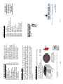
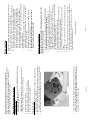
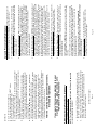
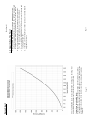
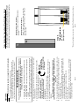
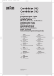
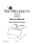
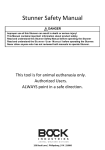
ON THE WEB at www.druckercompany.com
200 Shadylane Drive • Philipsburg, PA 16866
Phone: 814-342-6205 or 814-692-7661 • Fax: 814-692-7662
www.druckercompany.com
200 Shadylane Drive • Philipsburg, PA 16866
Phone: 814-342-6205 or 814-692-7661 • Fax: 814-692-7662
www.druckercompany.com
The Drucker Company
The Drucker Company warranties that
this centrifuge is free from defects in
materials and workmanship for 2 years.
Should the centrifuge require warranty or
out-of-warranty service
please contact:
WARRANTY
Operator’s Manual
Model 653V
Instructions to change this
setting are located on page 7.
10 Minutes
Rev. B
P/N 7711015
NOTE: The programmable run-time
has been preset for
pg. 2
pg. 3
pg. 4
pg. 5
pgs. 6,7
pg. 8
pg. 9
pg. 10
pg. 11
pg. 12
pg. 13
pg. 13
pg. 14
pg. 15
WARNING: For the safety of both the
operator and service personnel, care
should be taken when using this
centrifuge if handling substances that are
known to be toxic, radioactive or
contaminated with pathogenic
microorganisms. When Risk Group II
materials are used, (as identified in the
World Health Organization “Laboratory
Bio-Safety Manual”), a Bio-Seal should
be employed. In the event that materials
of a higher risk group are being used,
more than one level of protection must be
provided. The use of flammable or
explosive materials as well as those
materials which have a vigorous
chemical reaction is prohibited.
*
1.
p/n
p/n
Page 2
The rotor and rotor accessories are rated for a rotation frequency
of 3,400 RPM.
4.
3. .
7786048
7713030
NOTE: Your centrifuge
may have been shipped
with additional or alternate
accessories.
2.
2. One (1) six-place horizontal rotor
3. Six (6) 2-place 100mm test tube carriers
4. One (1) Operator's manual
1. One (1) Horizon centrifuge
The following items come standard with each Horizon centrifuge:
Supplied Equipment*:
x6
The Horizon Model 653V is a continuous-duty, electronically-controlled,
variable-speed, laboratory centrifuge with a lid safety interlock system.
The unit is controlled by an electronic push-button timer that is variable
from 1 to 30 minutes, for precise spin times and ease of use. Samples
can be safely viewed through the transparent lid. Entry into the machine
is restricted during operation by the safety interlock system. The Horizon
features a lighted control panel that displays the status of the machine,
easily viewable from a distance. For warranty information, turn to the
back cover.
Model Description:
Model Description, Supplied Equip.
Features, Specifications
Control Panel
Setup Location and Procedure
Programming Features
Operation
Tube Holder Configurations
Relative Centrifuge Force Chart
Care and Maintenance
Rotor Removal and Installation
Safety, Emergency Lid Removal
Calibration and Ground Testing
Troubleshooting
Available Accessories
Table of Contents
Description
Switch, lid safety
Motor, 1/2 H.P., Brushless
Brushless motor control PC board
Circuit Breaker
Power cord
Pawl, latch, lid
Knob, latch, lid
Lid
Air inlet cover, lid
Hinge, friction
Lid gasket
Rotor chamber gasket
Exhaust Air Deflector
2-Place Tube Carrier
6-Place Horizontal Rotor
p/n 1525
1525 Tube cushion
Contact your
authorized dealer or
The Drucker Co.
for information on
ordering parts or
accessories.
Page 15
ON THE WEB at
www.druckercompany.com
200 Shadylane Drive • Philipsburg, PA 16866
Phone: 814-342-6205 or 814-692-7661 • Fax: 814-692-7662
www.druckercompany.com
Available Accessories:
7751068
7735016
7717039
7751043
7760002
7714101
7714103
7712263
7713029
7724071
7732018
7732019
7713027
7713030
7786048
7724177 Rubber Foot
Part No.
Replacement Parts:
- Make sure that the unit has power.
- Make sure the lid latch is turned completely clockwise to its stop
position. The latch makes contact with a switch underneath the front
top of the cabinet. If this switch is not activated, the light will not turn
on and the machine will not run.
Solutions:
Solutions:
6. Problem:
Solutions:
Page 14
- Check the run preset by following the instructions on page 6. If the
preset is not the desired length, follow the instructions on page 7 to
change the preset.
The run time is not set to the desired length.
- The lid should remained locked until the rotor has come to a
complete stop and then unlock for 60 seconds. If additional unlock
time is needed, press the ’OPEN / EMERGENCY STOP’ button with
the machine plugged in and the rotor stopped. If the lid remains
locked after this and will not unlock, the electronics may have been
damaged. Contact your authorized dealer or The Drucker Company.
To access the rotor chamber, follow the procedure on page 13,
“Emergency Lid Removal”.
The machine does not unlock after a run has completed.
The latch light does not come on when the lid is closed.
Problem:
5. Problem:
- Check the electrical outlet.
- Make sure the lid latch is turned completely clockwise to its stop
position. When the lid is closed properly, the latch light on
the control panel will illuminate.
- Check the circuit breaker switch at the bottom right of the machine.
If the switch is white, the breaker has tripped. Contact your
authorized dealer or The Drucker Company for assistance.
- Make sure that the load is balanced. The 653V is equipped with out
of-balance detection. If an unbalanced load is detected, the unit will
safely power down.
- The printed circuit board may be damaged. Have a technician test
and replace the circuit board if necessary.
The centrifuge does not run.
- Check to see that the load is balanced.
- Make sure that nothing has fallen into the rotor chamber.
- Make sure that the rotor is installed correctly and that the center
thumb screw is tight.
- Have a technician test the motor and replace it if necessary.
Excessive noise when the machine is running.
- Make sure nothing has fallen into the rotor chamber.
- If there is nothing obstructing the rotor, contact your authorized dealer
or The Drucker Company for further assistance.
The rotor does not spin freely.
Solutions:
3. Problem:
Solutions:
2. Problem:
Solutions:
1. Problem:
Troubleshooting:
NOTE:
The latch must be turned
completely clockwise to its
stop position in order for the
centrifuge to operate.
500 to 3,200 (+/- 100) RPM
40 to 1540 xg
120 mL (12 x 10 mL)**
8.5 in. x 12.5 in. x 15.5 in.
1/2 H.P. Brushless DC
20 seconds
10 seconds
4 Amp. re-settable
1 to 30 min +/- 1%
1.5 Amps
115 Volts
50/60 Hz
30 lbs.
Page 3
** Maximum sample density is 1.15 grams / mL, (water density = 1.00 grams / mL)
Any use other than those specified by the manufacturer is explicitly prohibited.
Speed Range
Force Range
Maximum capacity:
Overall Dimensions (H x W x D):
Centrifuge Motor:
Nominal Acceleration Time:
Nominal Braking Time:
Protection Breaker:
Timer (electronic):
Current Requirement:
Voltage Requirement:
Frequency:
Weight:
Specifications:
• Swing-out horizontal rotor design incorporating a unique test tube
carrier that produces horizontally separated samples while requiring
no additional parts
• Variable-speed
• Cool-Flow air flow design that prevents overheating of samples
• Heavy gauge steel construction for safety and durability
• Lid safety switch that prevents the centrifuge from operating unless the
lid is closed and latched
• Removable rotor for easy cleaning
• Locking lid that allows entry into the centrifuge only after the rotor has
completely stopped
• Brushless DC Motor; requires no routine maintenance, cool running
• Clear lid for safe observation of samples and optical calibration of speed
• Electronically controlled timed operation variable from 1 to 30 minutes
• Push-button operation
• Indicator lights:
‘RUN’
green
-lights when power is applied to the motor
‘LATCH’
yellow -lights when the lid is closed and latched
‘UNLOCKED’
red
-lights when the lock system is deactivated
• Audible indicator at the end of each run
• Out-of-balance Detection
Features:
Lights up when the lid
has been closed and
latched properly.
‘LATCH’
INDICATOR
SPEED
CONTROL
Use this input to set the
running speed of the
centrifuge. The speed
may also be adjusted
while the centrifuge is
running.
‘UNLOCKED’ Lights up to indicate that
INDICATOR the locking mechanism
has been deactivated,
allowing access to the
rotor chamber .
Lights up when the
machine is in operation,
(power is being applied
to the motor).
‘RUN’
INDICATOR
SPEED
CONTROL
Control Panel:
‘LATCH’
Indicator
Allows access into the
rotor chamber by
disengaging the locking
mechanism. Entry is only
permitted when the rotor is
stopped. Pressing this
button during operation will
terminate the run and
unlock the lid after the
rotor has come to a stop.
The lid safety switch
prevents the centrifuge
from operating while the lid
is open. If the knob is not
turned completely
clockwise to its stop
position the centrifuge
cannot operate.
Programming functions are
accessed by first opening
the lid safety switch.
‘OPEN /
EMERGENCY
STOP’
BUTTON
LID
SAFETY
SWITCH
Page 4
Begins a new run, (the lid
must be closed, see pg. 6).
‘OPEN /
EMERG.
STOP’
Button
‘START’
Button
‘UNLOCKED’
Indicator
‘RUN’
Indicator
‘START’
BUTTON
Lid Safety
Switch
The Horizon model 653V complies with all requirements
of UL standard 3101-2-20.
Page 13
It is recommended that the top speed, ground continuity and line leakage be
tested every two years for continued safe operation. Contact your authorized
dealer or The Drucker Company for further information or testing availability.
Calibration and Earth Ground Testing:
In the event of power failure, it may be impossible
to unlock the lid by conventional means. In this
case, entry into the rotor chamber may be made
by removing the latch label and using a pen to
manually disengage the locking mechanism (see
photo). Pull the mechanism towards the control
panel and then unlatch and open the lid. If the
unit is damaged, contact your authorized dealer
or The Drucker Company.
Emergency Lid Removal:
Circuit Breaker: The Horizon is protected with a 4 Amp circuit breaker
located at the rear of the machine mounted to the base. Any electrical short
circuit will cause the breaker to cut power to the machine.
Note: After the centrifuge has started spinning, it may be possible to rotate
the lid knob enough to cause the pawl to lose contact with the lid safety
switch. If this happens, the centrifuge motor may lose power, but the lid
will still remain locked. If the knob is accidentally moved and this
situation should occur, rotate the knob fully clockwise to its stop position
and the centrifuge will resume operation.
Horizon Lid Safety Interlock System: In addition to the Lid Safety Switch,
the Horizon has a true “0 RPM” lid locking system. The lid safety interlock
system keeps the lid locked at all times, (even during power failure), and
requires that the rotor be at rest in order to unlock the lid. The centrifuge will
not allow entry into the rotor chamber unless the centrifuge has power and the
rotor is stopped. To open the lid, make sure that the centrifuge is plugged in
and, with the rotor stopped, press the ‘OPEN / EMERGENCY STOP’ button.
Horizon Lid Safety Switch: The Horizon lid is secured to the top of the
cabinet by a latching knob and pawl system. When the knob is rotated
clockwise, the pawl grips the underside of the cabinet opening and prevents
the lid from opening. A mechanical stop positions the pawl and prevents it from
rotating completely. When rotated to the stop position, the pawl makes contact
with a micro-switch mounted underneath the cabinet top. The lid safety switch
prevents the centrifuge from operating while the lid is open. An indicator light
on the front of the machine will light up when the lid has been latched properly.
Safety:
Remove the test tube carriers.
Remove the thumb screw in the center of the rotor.
Pull up on the rotor until it is clear of the motor shaft.
Remove the rotor from the rotor chamber.
4.
Page 12
It is recommended that the initial setup procedures be performed to ensure
that the rotor has been installed correctly and that no damage has been
done to the centrifuge during the rotor installation or possible rotor chamber
cleaning. See page 5 for this procedure.
To install the rotor:
1. Place the rotor into the rotor chamber at an angle (see picture) and then
position it onto the rotor shaft cone..
2. Once a proper fit has been achieved, replace the thumb screw and tighten.
The thumb screw must be properly tightened or the rotor may be damaged.
3. Replace the tube carriers and verify that they are seated properly.
2.
3.
4.
5.
CAUTION: Unplug the centrifuge from the electrical outlet at this time to
eliminate the possibility of electrical shock or other injury.
To remove the rotor:
1. Unlock the centrifuge by pushing the ‘OPEN / EMERGENCY STOP’ button
and unlatch and open the lid.
Rotor Removal and Installation:
Before using any cleaning or decontamination methods except those
recommended by the manufacturer, users should check with the manufacturer
that the proposed method will not damage the equipment. See page 11,
(bottom), for the recommended cleaning solutions.
Unpack the centrifuge and verify that all of the supplied equipment is present.
Choose a setup location which meets the following criteria:
a) A bench top clearance height of 24” is required in order to open the lid.
b) The clearance envelope is the space around the centrifuge which is
required for safety. Choose a setup location which will allow for a
clearance envelope of at least 28” x 28”, (with the centrifuge at the
center). No person or hazardous material shall be permitted in the
clearance envelope during operation. The operator time within the
envelope shall be limited to the time necessary for loading, unloading and
centrifuge operation only.
c) Proper ventilation is necessary to prevent the overheating of samples as
well as premature failure of the centrifuge. Choose an area which will
allow unencumbered air flow.
d) No adjustment is necessary for leveling the centrifuge, however,
the surface should be flat and level.
e) Be sure the outlet is always within reach as the line cord is
the means of emergency disconnection!
7.
6.
5.
3.
4.
2.
1.
Page 5
(continued next page)
Plug the centrifuge in to an approved electrical outlet. For electrical
safety, the unit must always be properly grounded.
For safety purposes, the locking system is always activated. To
deactivate the system, (in order to insert or retrieve samples), press the
‘OPEN / EMERGENCY STOP’ button on the control panel. The
‘UNLOCKED’ indicator light should illuminate. If it does not, refer to page
14 on troubleshooting. The lid will be unlocked for 15 seconds after pushing
the ‘OPEN / EMERGENCY STOP’ button.
Turn the latch counter-clockwise and open the lid.
Spin the rotor by hand; check for free and level rotation. If the rotor does
not spin freely, refer to page 14 on troubleshooting.
Check the thumb screw in the middle of the rotor and make sure that it
is tight.
Place the test tube carriers inside the rotor and verify that they are seated
properly.
Close the lid. Rotate the lid knob clockwise to its complete stop position.
The ’LATCH’ indicator light should be illuminated. If it is not, make sure that
the lid is latched properly. The centrifuge will not run unless the lid is
latched and the ’LATCH’ light is on.
If any problems are found during the initial setup procedure, refer to the
troubleshooting section on page 14.
Initial Setup Procedure:
1.
2.
Setup Location:
If you would like to make adjustments to your
machine’s settings, please continue on to
“Additional Set-Up Procedures”.
After the centrifuge has passed this procedure,
it is ready for operation.
Turn the speed control to Full Speed.
Turn the centrifuge on by pushing the ‘START’ button.
The ‘RUN’ indicator light will illuminate.
The unit will accelerate to full speed.
Listen to the sound of the centrifuge. A smooth whirring sound should be
heard. If there are any loud or unusual sounds, stop the centrifuge by
pushing the ’OPEN / EMERGENCY STOP’ button immediately and refer
to page 14 on troubleshooting.
While the machine is running, try to turn the latch counter-clockwise.
Power may be cut to the motor but you should not be able to fully turn
the latch. If it is possible to turn the latch and open the lid while the unit
is running, contact your authorized dealer or The Drucker Company.
Close and latch the lid.
Push the ‘OPEN / EMERGENCY STOP’ button. The ‘RUN’ indicator
light should go out and the motor should slow to a stop.
The lid should remain locked until the rotor has stopped. If the machine
unlocks prematurely, contact your authorized dealer or The Drucker
Company. Once the rotor has stopped, a beeper will sound and the
interlock system will become disengaged for sixty (60) seconds. The
‘UNLOCKED’ indicator light will be illuminated during this time.
To gain entry into the centrifuge after this period has ended, simply press
the ‘OPEN / EMERGENCY STOP’ button. The lid will unlock for fifteen
(15) additional seconds. Repeat if necessary.
When you release the ‘START’ button, the ‘RUN’ indicator light will begin
to flash. Each flash of the ‘RUN’ indicator light represents one minute of
run time. If the time indicated is not desired, follow the instructions on
the rear of the centrifuge to change it.
b.
Page 6
(Continued next page)
Push and hold the ‘START’ button for approximately three (3) seconds.
The ’LATCH’ indicator light will begin to flash; indicating program mode.
a.
NOTE: The centrifuge must be plugged in and the lid must be opened to
access programming functions!
1. Verify the Run-Time Preset:
Additional Set-Up Procedures (Optional):
16.
15.
14.
13.
8.
9.
10.
11.
12.
(Continued)
Keep the Tube Carriers Clean: NOTE: Always follow the safety guidelines of
your laboratory to properly clean up and/or dispose of materials in the event
that a substance known to be potentially toxic, radioactive or contaminated with
a pathogenic microorganism is spilt in or on the centrifuge. Small glass
fragments left in the tube carrier after a tube breakage may adhere to the next
test tube inserted in that carrier. When this tube is handled, these fragments
may puncture protective gloves and lacerate the operator's fingers or hand.
Remaining fragments may provide stress points on subsequent tubes and
result in additional breakage. If a tube breakage occurs, carefully remove the
tube carrier. Properly dispose of the sample and tube fragments and
thoroughly clean both the inside and outside of the tube carrier. Insert a new
tube cushion (if necessary) and replace the tube carrier in the rotor.
Motor and Electrical Maintenance: The Horizon uses a brushless DC motor.
It should not need servicing for the life of the centrifuge. The electrical
components are selected for high reliability and should not need service.
Keep the Rotor Chamber Clean: Every six months, or whenever there is a
tube breakage, (refer to the note in #3), it may be necessary to remove the
rotor and clean the rotor chamber. Follow the instructions on page 9 to remove
and re-install the rotor.
3.
4.
5.
6.
Always Spin Balanced Loads: Make certain that opposing tube holders are
filled with an equal volume sample or an equivalent weight water-filled tube.
The Horizon has a cushioned motor mounting design which, along with it’s
rubber feet, produces excellent vibration dampening. However, out-of-balance
loads may break glass test tubes and may produce unsatisfactory separation
results. Proper load balancing will improve sample separation and extend the
life of the centrifuge. Refer to page 8 on balanced loads for additional
information on balancing the load.
2.
Page 11
Rotor and Tube Carriers: It is recommended that the tube carriers
be replaced after 24 months. Periodically check the thumb screw in the
center of the rotor to ensure that it remains tight.
CAUTION DURING CLEANING: Once the lid has been opened, unplug the
line cord from the electrical outlet to eliminate the risk of electric shock during
cleaning.
The rotor chamber, rotor and accessories shall be thoroughly cleaned using
either isopropyl alcohol, soap and water or bleach. The use of Fully/Partially
Halogenated Hydrocarbons, Ketones, Esters and all other chemicals not
prescribed by the manufacturer may cause damage to the rotor and tube
holders and shall not be used.
Apply cleaning solutions with a towel or cloth. Do not submerge the
centrifuge in water or other cleaning solutions as this will cause damage
and void your warranty!
Provide Adequate Ventilation: For cooling purposes, the Horizon draws in
ambient air through the rear of the lid and exhausts this air out the rear of the
base. Do not block the rear of the centrifuge as this will not allow the machine
to properly ventilate itself.
1.
With proper care and maintenance, your Horizon centrifuge will provide years of
laboratory service. For proper care, the following steps should be taken:
Care and Preventative Maintenance:
Page 10
Instructions for using this chart:
Find the desired force on the left-hand column and then follow across at that
level until you meet the line for the tube holder you use. Follow this intersection
point down to the bottom of the chart to reveal the speed required to produce
that force.
This chart will allow you to set your Model 653V centrifuge to a desired g-force
by providing the appropriate speed for the rotor you are using.
Force Chart:
Press the ‘START’ button once for each minute of desired run time.
The ‘RUN’ indicator light will flash once for each entered minute.
Press the ‘OPEN / EMERGENCY STOP’ button to save the change and
exit programming mode.
If desired, use the “verify the preset time” procedure to confirm that the
adjustment is correct.
b.
c.
d.
Page 7
Push and hold both the ‘START’ and ’OPEN / EMERGENCY STOP’
buttons for approximately three (3) seconds. The ’LATCH’ indicator light
will begin to flash; indicating program mode. Release the two buttons.
a.
2. Change the Run-Time Preset:
(Continued)
Opposing tube carriers must be identical and must contain the same
cushion, or none at all.
Opposing tube carriers must be empty or loaded with equally weighted
samples.
If an odd number of samples is to be spun, fill a tube with water to match
the weight of the unpaired sample and place it across from this sample.
Place the test tube samples into the tube carriers. Be sure to follow the rules
for balanced loads.
Close the lid and turn the lid knob clockwise to its complete stop position.
The ’LATCH’ indicator light should turn on to
NOTE:
indicate that the latch is closed properly.
Latch
the lid knob
If the lid knob is not completely
clockwise to its stop
latched, the ‘LATCH’ indicator light
position or the centrifuge
will not turn on and the centrifuge
will not operate!
will not operate!
Set the speed control to the desired speed.
Turn on the machine by pushing the ‘START’ button on the control panel.
The centrifuge should begin to spin. The ‘RUN’ indicator light should
illuminate.
3.
2.
1.
Your centrifuge must contain a balanced load in order to work properly.
To ensure that the load is balanced, keep these rules in mind when
inserting cushions and test tube samples:
BALANCED LOADS
Plug the centrifuge into an approved electrical outlet.
Push the ‘OPEN / EMERGENCY STOP’ button and then open the lid.
Insert cushions (if needed) into the tube carriers for the tube size you are
using. Refer to ‘Tube Carrier Configurations’ (page 9) for assistance.
Page 8
IF A PROBLEM IS FOUND DURING A SPIN THAT REQUIRES THE
CENTRIFUGE TO SHUT DOWN, PRESS THE ‘OPEN / EMERGENCY STOP’
BUTTON !
9. The run indicator light will begin to flash when one minute remains in the cycle.
10. After time has elapsed, the ‘RUN’ indicator light will extinguish and the rotor
will brake to a complete stop.
11. The ‘UNLOCKED’ indicator light will illuminate, a beeper will sound and the
locking mechanism will disengage allowing entry into the rotor chamber. If it
does not, refer to page 14 on troubleshooting.
12. Turn the lid knob counter-clockwise and open the lid.
13. Remove the samples.
14. If the machine re-locks before the samples are removed, press the ‘OPEN /
EMERGENCY STOP’ button to unlock the lid for an additional fifteen (15)
seconds. Repeat if necessary.
6.
7.
8.
5.
4.
1.
2.
3.
NOTE: Follow the initial setup procedure on page 5 before initial operation.
Operation:
p/n 1525
(configuration B)
1 Inch
Tube Cushions
B.
Configuration B (75mm tubes):
Place a 1” tube cushion in the bottom of each of the
tube locations in the tube holder as shown in the picture to the right.
Configuration A (100 mm tubes):
Use the tube holder as is with no additional tube
cushions.
Page 9
* This part is available as an accessory. Contact The Drucker Company for assistance.
A.
A.
The horizontal rotor shipped with your Horizon centrifuge is capable of spinning
tubes up to 16mm x 100mm. Use the following chart and drawing to determine
which tube holder and cushion combination should be used with your application.
Tube Holder Configurations (Plastic Holders Only):