1
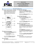
Model 532 mA/V Loop Calibrator with Loop Diagnostic Operating Instructions Practical Instrument Electronics A. j Basic Keypad Operations EZ-Check™ Switch/EZ-Step™ Pushbutton Slide the switch to select the user stored values for calibration points. Press the button to adjust the output by the user defined step size. Press and hold the button to activate the auto step/ramp mode. m UNITS/STEP TIME Button Press and release UNITS/STEP TIME to change how current is displayed: either in milliamperes or % of 4-20 mA. Voltage is only displayed in volts. Press and hold UNITS/STEP TIME to change step size. Refer to section H. n READ/SOAK TIME Button Press and release READ/SOAK TIME to change read modes. These are: • Read Milliamps • Power and Measure 2-Wire Transmitter • Read Volts Press and hold READ/SOAK TIME to change soak time. Refer to section H. k SOURCE/STEP SIZE Button Press and release SOURCE/STEP SIZE to change source modes. These are: • Source Milliamps • 2-Wire Transmitter Simulate • Source Volts Press and hold SOURCE/STEP SIZE to change step size. Refer to section H. l STORE/CLEAR/DIAGNOSTIC Button In any source mode: Press STORE/CLEAR/DIAGNOSTIC to save the current reading in the EZ-Check• HI or LO position. The EZ-Check• switch must be set to HI or LO. The display will flash “STORED” to confirm. In any read mode: Press STORE/CLEAR/DIAGNOSTIC to clear the values saved in the EZ-Check• HI and LO positions. The display will flash “CLEARED” to confirm. Press and hold STORE/CLEAR/DIAGNOSTIC to activate diagnostic mode. See section I. EZ-Dial™ Knob Turn the EZ-Dial• knob to adjust the output level. Press and turn to adjust 100X faster. ON/OFF Button Press ON/OFF to turn the Model 532 on or off. Please contact an authorized sales representative at 800-346-4620 or order at www.Instrumentation.com Practical Instrument Electronics, Inc. Copyright • 2011. All rights reserved. 532-9002 Rev C 7/13/11 1-8 Model 532 Operating Instructions B. Model 532 Configuration Press the EZ-Dial• Knob while turning the Model 532 on to access the configuration mode. Turn the EZ-Dial• Knob to select configuration items. Press the EZ-Dial• Knob to change configuration items. Turn the unit off or just wait approximately 8 seconds to exit the configuration mode. Auto Off - ON (default)/OFF Auto Off is ON, by default, to save battery life by turning the unit off after 30 minutes of inactivity. Turn Auto Off to OFF to prevent automatic shutdown. This is typically useful for manual loading or continuous use. EZ-Step• - ON/OFF (default) If EZ-Step• is ON manual and automatic stepping/ramping is available. If EZ-Step• is OFF the EZ-Step• pushbutton will be disabled and the step direction indicator will not be displayed. HART® Compatibility Mode - ON/OFF (default) The Model 532 has a HART® compatibility mode. This mode is useful when the devices being powered communicate using the HART® protocol. In this mode the Model 532 connects a 250 Ω load resistor in series with the output in both Source and Power Measure 2-Wire transmitter modes. This eliminates the requirement of an external 250 Ω load resistor. This resistor is typically shown in connection diagrams and manuals for HART® devices. If HART® Compatibility Mode is ON, a 250 Ω load resistor is automatically switched in series with the output in Source and Power Measure 2-Wire Transmitter modes. The output compliance with HART® Compatibility Mode ON is 950 Ω at 20 mA. If HART® Compatibility Mode is OFF there is no 250 Ω load resistor in series with the output. This will increase the output compliance voltage to drive 1200 Ω at 20 mA. EZ-Check• HI/LO Readings ON/OFF (default) If the EZ-Check• HI/LO Readings option is ON, the highest and lowest readings will automatically be saved in the HI and LO EZ-Check™ positions. If this option is OFF the HI and LO positions will show the current reading. Loop Diagnostic ON (default)/OFF Loop Diagnostic may be turned off to prevent entry into diagnostic mode. This may make the Model 532 simpler to operate by eliminating accidental entry into diagnostic mode. Factory Reset ON/OFF (default) If Factory Reset is ON, the unit will restore all factory defaults when the Model 532 is turned OFF and back ON. This will reset any changes made in the Model 532 Configuration options, returning the unit to its simplest factory configuration. Please contact an authorized sales representative at 800-346-4620 or order at www.Instrumentation.com Practical Instrument Electronics, Inc. Copyright • 2011. All rights reserved. 532-9002 Rev C 7/13/11 2-8 Model 532 Operating Instructions C. EZ-Dial• Knob Adjust the output up and down with the EZ-Dial• knob. The increment is 0.001 mA (or 0.01 % if display units are % of 4-20 mA.) Press while turning to adjust 100X faster – 0.100 mA (or 1.00 %.) D. EZ-Check• Switch The EZ-Check™ switch has three positions -- high, set, and low. Its position is shown at the left edge of the display with “HI” and “LO” indicators. Use of the EZ-Check• switch depends on mode: Source Modes: Slide the EZ-Check• switch to the HI and LO positions to recall the settings stored in those positions. While in the HI and LO positions, dial the EZ-Dial• knob to change the display. Press STORE/CLEAR to save new settings in the HI and LO positions. The display will flash “STORED” to confirm. Hint: For faster calibrations, the position of the switch can be felt. This feature allows continuous monitoring of the device being calibrated without looking back at the Model 532 display. This is also useful in poor lighting or under difficult operating conditions. Read Modes: In read modes, the Model 532 calibrator records the maximum and minimum readings observed in each mode. Slide the EZ-Check• switch to the HI and LO positions to display the readings. Press STORE/CLEAR to clear the readings. The display will flash “CLEARED” to confirm. By default, the Model 532 has EZ-Check• HI/LO Readings OFF. Refer to Model 532 Configuration, section B. E. EZ-Step• Pushbutton/ Manual Step The EZ-Step• pushbutton is a feature only in source modes. Press and hold the EZ-Step• pushbutton for less than one second to cause the output to step up or down by the EZ-Step• size. The EZ-Step• direction is indicated on the display ( step direction. or ). Press the EZ-Dial• knob to change the Stepping and auto step/ramp limits are defined by the EZ-Check• HI and LO settings. The step direction changes when a limit is reached. The step size is computed as the difference between the EZ-Check• HI and the EZ-Check• LO divided by the number of steps. See section H. By default, the Model 532 has EZ-Step• OFF. Refer to Model 532 Configuration, section B. F. Auto Step/Ramp Press the EZ-Step• pushbutton for more than one second to activate auto step/ramp mode. The Model 532 will automatically step by the selected EZ-Step• size and time. Press the EZ-Step• pushbutton again to deactivate auto step/ramp mode. The EZ-Step• direction is indicated on the display ( or ). Press the EZ-Dial• knob to change the step direction. The step direction can be changed while automatically stepping/ramping. Please contact an authorized sales representative at 800-346-4620 or order at www.Instrumentation.com Practical Instrument Electronics, Inc. Copyright • 2011. All rights reserved. 532-9002 Rev C 7/13/11 3-8 Model 532 Operating Instructions Stepping and auto step/ramp limits are defined by the EZ-Check• HI and LO settings. The step direction changes when a limit is reached. Figure 1 shows how the Step/Ramp Parameters are used to configure automatic stepping/ramping. Figure 1 24 ramp time 20 step time = ramp time • # of steps mA 16 soak time 12 8 step size = (EZ-Step HI – EZ-Step LO) • # of steps 4 0 1 2 3 4 5 6 7 8 9 10 11 12 13 14 15 time Note: The Model 532’s ability to detect overload/undervoltage conditions may be limited by the rate of change in the output when using automatic stepping/ramping. Turn auto step/ramp off while connecting or disconnecting the Model 532. G. Quick Reference Bar Graph The Quick Reference Bar Graph indicates the input and output level on the Model 532 in % of 4-20 mA with 1% resolution. Please contact an authorized sales representative at 800-346-4620 or order at www.Instrumentation.com Practical Instrument Electronics, Inc. Copyright • 2011. All rights reserved. 532-9002 Rev C 7/13/11 4-8 Model 532 Operating Instructions H. Manual Step and Auto Step/Ramp Parameter To Change the EZ-Step• Size: 1. 2. 3. 4. 5. Press and hold the SOURCE/STEP SIZE button for more than ¾ of a second. The display will flash “EZ-STEP SIZE”. Turn the EZ-Dial• knob to select from 2 to 16 steps between the EZ-Check• limits. Turn the EZ-Dial• clockwise past 16 steps to select continuous ramp mode. Press the SOURCE/STEP SIZE button again to return to the normal display. Note: If the EZ-Step• option is turned off, the display will flash “EZ-STEP OFF”. Refer to Model 532 Configuration, section B. To Change the EZ-Step• Time: Press and hold the UNITS/STEP TIME button for more than ¾ of a second. 2. The display will flash “EZ-STEP TIME”. 3. Turn the EZ-Dial• knob to select from 5 to 900 second ramp time. The time per step is calculated based on the selected EZ-Step• size. 4. Press the SOURCE/STEP SIZE button to return to the normal display. 1. To Change the Soak Time: Press and hold the READ/SOAK TIME button for more than ¾ of a second. 2. The display will flash “SOAK TIME”. 3. Turn the EZ-Dial• knob to select from 0 to 900 second soak time. Note: A soak time of 0 defeats the soak period. The step time will be used instead. 4. Press the READ/SOAK TIME button again to return to the normal display. 1. To Change the EZ-StepTM Direction: 1. Press and release the EZ-Dial• knob without turning. 2. The display will change to show the EZ-Step• direction selected ( or ). Please contact an authorized sales representative at 800-346-4620 or order at www.Instrumentation.com Practical Instrument Electronics, Inc. Copyright • 2011. All rights reserved. 532-9002 Rev C 7/13/11 5-8 Model 532 Operating Instructions I. Loop Diagnostic Press and hold the STORE/CLEAR/DIAGNOSTIC button for more than ¾ of a second to activate loop diagnostic mode. This is available in each of the Model 532’s operating modes. Read Modes: Read Milliamps Loop current is displayed. Power and Measure 2-Wire Transmitter Loop current, voltage, and resistance is displayed. Read Volts Voltage is displayed. Source Modes: The EZ-Dial• knob, EZ-Check• switch, and EZ-Step• pushbutton function normally when the loop diagnostic is activated. Source Milliamps Loop current, voltage, and resistance is displayed. The resistance is highlighted if it exceeds the Model 532’s output capability (1200 • at 20 mA with HART• Compatibility disabled.) 2-Wire Transmitter Simulate Loop current is displayed. The Model 532 automatically performs a test every 7 seconds to compute the loop power supply voltage and loop resistance. The Model 532 requires approximately 2 volts across its terminals to operate in 2 Wire Simulate mode. The voltage display is highlighted if there is less than 2 volts present. Source Volts Loop current, voltage, and resistance is displayed. The resistance is highlighted if it exceeds the Model 532’s output capability (20 mA into 1200 • with HART• Compatibility disabled.) Please contact an authorized sales representative at 800-346-4620 or order at www.Instrumentation.com Practical Instrument Electronics, Inc. Copyright • 2011. All rights reserved. 532-9002 Rev C 7/13/11 6-8 Model 532 Operating Instructions In all loop diagnostic modes, AC voltage is displayed. If more than 2 VAC is present on the Model 532’s terminals, the display is highlighted to alert the user of a potential problem. In all loop diagnostic modes, HART• activity is indicated with “• HART DETECTED • ” . The • symbols flash on and off with the actual HART• messages. J. Modes of Operation Read Milliamp Connect the Model 532 in series with the process loop to monitor current. Observe correct polarity. Current limiting above 24.000 mA is indicated by a flashing “CURRENT LIMITED” display. Power and Measure 2 Wire Transmitter The Model 532 provides power to the process loop while displaying output current. Use this mode to test a transmitter’s ability to control loop current. Current limiting above 24.000 mA is indicated by a flashing “CURRENT LIMITED” display. Read Volts The Model 532 measures +/- 30 VDC with 4X overrange ability. The display flashes “OVERRANGE” when the 30 volt limit is exceeded. 0.001 volt resolution below 24.00 volts provides the ability to calibrate 1-5 volt instrumentation. Please contact an authorized sales representative at 800-346-4620 or order at www.Instrumentation.com Practical Instrument Electronics, Inc. Copyright • 2011. All rights reserved. 532-9002 Rev C 7/13/11 7-8 Model 532 Operating Instructions Source Milliamp Connect the Model 532 directly to 4-20 mA receiver equipment, alarms, panel meters, etc. Use the EZ-Dial• Knob and EZ-Check• Switch to adjust loop current. The display flashes “HIGH Ω” when the loop resistance is too high or the leads are open. 2 Wire Transmitter Simulate Substitute the Model532 for a 2 wire transmitter. Use the EZ-Dial• Knob and EZCheck• Switch to adjust loop current. At least 2 volts of loop power is required, else the display flashes “CHECK LOOP SUPPLY.” Source Volts The Model 532 sources 0.000-24.000 volts. This is useful for powering transmitters and receiver equipment. Use the EZ-Dial• Knob and EZ-Check• Switch to adjust output voltage. The display flashes “LOW • ” when the output is overloaded. K. Warranty Our equipment is guaranteed against defective material and workmanship (excluding batteries) for a period of three years from the date of shipment. Claims under guarantee can be made by returning the equipment prepaid to our factory. The equipment will be repaired, replaced or adjusted at our option. The liability of Practical Instrument Electronics (PIE) is restricted to that given under our guarantee. No responsibility is accepted for damage, loss or other expense incurred through sale or use of our equipment. Under no condition shall Practical Instrument Electronics, Inc. be liable for any special, incidental or consequential damage. Please contact an authorized sales representative at 800-346-4620 or order at www.Instrumentation.com Practical Instrument Electronics, Inc. Copyright • 2011. All rights reserved. 532-9002 Rev C 7/13/11 8-8